
Signal Processing
Index 38
Sine to rectangular wave conversion circuit
Published:2012/9/18 21:21:00 Author:Ecco | Keyword: Sine to rectangular wave , conversion
We have already given many posts on Op-Amp circuits. But the list of applications of Op-Amp will be keep on going. ?The best Op-Amp circuit which is used to convert sine waveform into rectangular waveform is the schmitt trigger circuit.To avoid the false triggering, a positive feedback is used in a comparator circuit of an Op-Amp. Thus the comparator with positive feedback is called Schmitt trigger or regenerative comparator. The inverting schmitt trigger mode produces opposite polarity output. This is?fed back to the non-inverting input which is of same polarity as that of output. This ensures positive feedback.
The above shown schematic is the sine to rectangular conversion circuit. For proper conversion of input signal from sine to rectangular, the input must be large enough to pass through both the tripping voltages.
When the input signal is periodic, for any shape of the input signal, the Schmitt trigger always produces rectangular waveform.
Practically sometimes a capacitor C1 is connected in parallel with R1, as shown in the above schematic. The stray capacitance C2 forms the bypass circuit with R2. The use of speed-up capacitor C1 across R1 eliminates the effect of stray capacitance C2. Without speed-up capacitor, the stray capacitance C2 is required to be charged before the non-inverting input voltage changes. The speed-up capacitor used supplies the necessary charge to C2. For neutralizing the effect of stray capacitance, the minimum value of speed-up capacitor must be,
C1(min) = (R2/R1) C2.
When C1 is selected is greater than C1(min) then the switching of the output is very fast.
The frequency of the output of the Schmitt trigger is same as the frequency of the input signal.
The peak to peak value of the output rectangular waveform is approximately 2Vsat. (View)
View full Circuit Diagram | Comments | Reading(813)
Basic JFET Pierce Crystal Oscillator
Published:2012/9/17 21:42:00 Author:Ecco | Keyword: Basic , JFET, Pierce , Crystal Oscillator
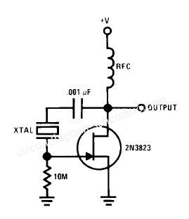
This circuit is a series of JFET Pierce Crystal Oscillator. JFET Pierce crystal oscillator allows a wide range of crystal frequencies to be used without modification of the circuit. Since the JFET gate did not contain crystals, Q both maintained that insure a good frequency stability. (View)
View full Circuit Diagram | Comments | Reading(3661)
Simple Wien-Bridge Oscillator
Published:2012/9/17 21:40:00 Author:Ecco | Keyword: Simple, Wien-Bridge Oscillator
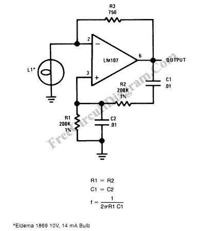
Incandescent lamp has been used to reduce harmonic distortion in sine oscillator circuit. The nonlinear resistance characteristic of the lamp filament help the circuit to shape the signal to approximate the ideal sine wave. Here is the classic Wien-bridge oscillator circuit using the incandescent lamp.
Source: freecircuitdiagram (View)
View full Circuit Diagram | Comments | Reading(0)
Voltage Controlled Oscillator 1.2GHz
Published:2012/9/17 21:38:00 Author:Ecco | Keyword: Voltage Controlled Oscillator, 1.2GHz
Since high frequency voltage-controlled oscillators, or VCOs, are not easy to construct, Maxim (www.maxim-ic.com) has produced an integrated 1.2GHz oscillator, the MAX2754. The center frequency is set using the TUNE input, and a linear modulation input allows the frequency to be modulated. The IC is available in an 8-pin μMAX package, operates from a supply of between 2.7 V and 5.5 V, and draws a current of less than 2 mA. Both TUNE and MOD operate over control voltage range of +0.4 V to +2.4 V. TUNE allows the VCO frequency to be adjusted from 1050 MHz to 1270 MHz. (View)
View full Circuit Diagram | Comments | Reading(970)
Astable/Monostable oscillator using 555 IC
Published:2012/9/17 21:37:00 Author:Ecco | Keyword: Astable/Monostable oscillator , 555 IC
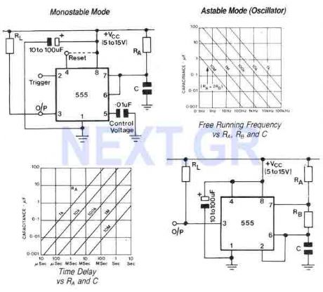
The 555 is a highly stable device for generating accurate time delays or oscillation. Aditional terminals are provided for triggering or resetting if desired. In the time delay (monostable) modeof operation the time is precisely controlled by one extrernal resistor and one capacitor. For stable operation as an oscillator, the free running frequency and the duty cycle are both accurately controlled with two external resistors and one capacitor. (View)
View full Circuit Diagram | Comments | Reading(1276)
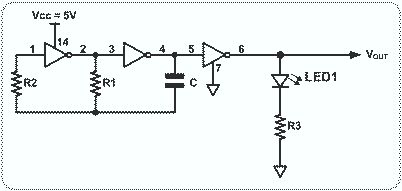
Square Wave Generator with CMOS 74C14
Published:2012/9/17 21:33:00 Author:Ecco | Keyword: Square Wave Generator, CMOS
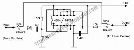
This circuit is based on CMOS IC 74C14. The output of this circuit is from 0V to +12V, and is fed to the 10k level pot by a 10k resistor. This reduces the level to 6V P-P, which is equal to 3V RMS. The input circuit is designed to ensure that the Schmitt input is supplied from a 1/2 supply voltage (6V), so the applied AC will swing evenly about this point and produce a symmetrical square wave.
(View)
View full Circuit Diagram | Comments | Reading(1715)
Adjustable Sine Square Wave Oscillator
Published:2012/9/17 21:31:00 Author:Ecco | Keyword: Adjustable, Sine Square Wave, Oscillator
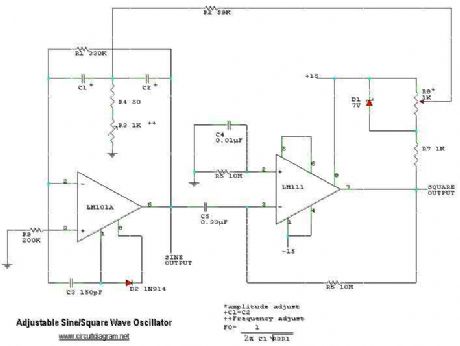
This is a adjustable sine square wave oscillator circuit. (View)
View full Circuit Diagram | Comments | Reading(1625)
RF oscillator circuit (2N3904)
Published:2012/9/17 21:31:00 Author:Ecco | Keyword: RF oscillator
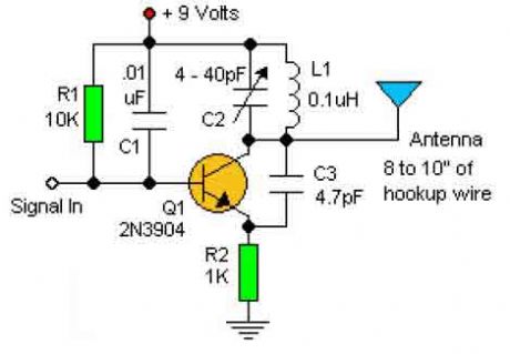
This basic RF oscillator circuit is easy to build and the components are not critical. Most of them can be found in your junk parts box. The L1 antenna col can be made by close winding 8 to 10 turns of 22 gauge insulted hookup wire around 1/4 inch form such as a pencil. (View)
View full Circuit Diagram | Comments | Reading(5464)
100 MHz RF Oscillator Circuit
Published:2012/9/17 21:30:00 Author:Ecco | Keyword: 100 MHz , RF Oscillator
The following schematic diagram shows the design of a 100 MHz Radio Frequency RF Oscillator Circuit. The electrets microphone picks up and amplifies sound then fed it into the audio amplifier stage built around the first transistor. The output from the collector is fed into the base of the second transistor where it modulates the resonant frequency of the tank circuit (the 5 turn coil and the trim cap) by varying the junction capacitance of the transistor. (View)
View full Circuit Diagram | Comments | Reading(1613)
Basic Hartley Oscillator
Published:2012/9/17 21:30:00 Author:Ecco | Keyword: Basic , Hartley Oscillator
The Hartley Oscillator is characterised by an LC circuit in its collector. The base of the transistor is held steady and a small amount of signal is taken from a tapping on the inductor and fed to the emitter to keep the transistor in oscillation. (View)
View full Circuit Diagram | Comments | Reading(1450)
The test signal generator using modulator circuit
Published:2012/9/17 1:32:00 Author:Ecco | Keyword: test signal generator , modulator
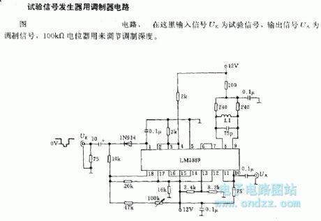
In the circuit shown as figure, it is input signal UE as test signal, the output signal UA is modulation signal, 100 KΩ potentiometer is used to adjust modulation depth.
(View)
View full Circuit Diagram | Comments | Reading(951)
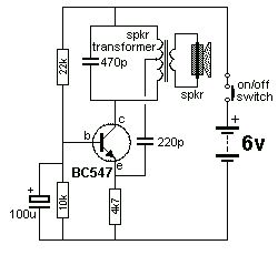
Simple Colpitts Oscillator circuit
Published:2012/9/16 21:58:00 Author:Ecco | Keyword: Simple, Colpitts Oscillator
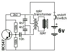
The Colpitts Oscillator is characterised by tapping the mid-point of the capacitive side of the oscillator section. The inductor can be the primary side of a speaker transformer. The feedback comes via the inductor. (View)
View full Circuit Diagram | Comments | Reading(2146)
Astable Multivibrator with 2 Transistors
Published:2012/9/16 21:57:00 Author:Ecco | Keyword: Astable Multivibrator , 2 Transistors
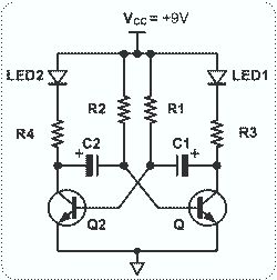
This circuit is basically simple and easy to build, it uses two transistors as active components and a few passive components like resistors, capacitors and two LEDs. The circuit makes use of the MPS2222 transistor. You can use any NPN type transistor as the basis of your circuit provided that, the transistors Emitter-Base Voltage is less than 12V and has a maximum value of 5V. (View)
View full Circuit Diagram | Comments | Reading(4171)
12 coil Pulse Monopole/Generator
Published:2012/9/16 21:50:00 Author:Ecco | Keyword: 12 coil, Pulse Monopole, Generator
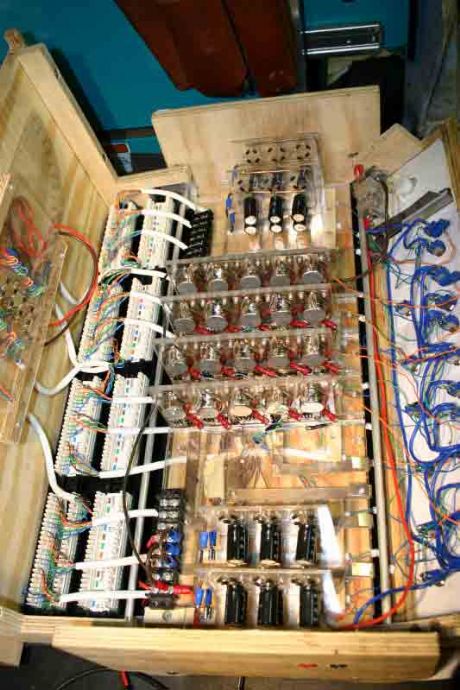
Fully functional Bedini motor pulse charger powered by micro-controller. All variables (coil sensitivity thresh-hold and motor power (current) consumption) controlled by software program. I can manipulate triggering of motor and triggering of cap pulse disharge. Results have convinced me this is the cheaper way to build and experiment. I haven't blown any components yet with this experiment with no protection Neon (Ne2) on transistor. (View)
View full Circuit Diagram | Comments | Reading(2220)
Self runner Generator
Published:2012/9/16 21:42:00 Author:Ecco | Keyword: Self runner Generator
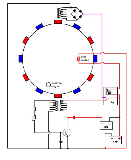
The timing must be exact to get those high voltage spikes. I used a tiny magnet on the rotor, that triggered a reedswitch allowing the relay to pulse the energy from the recovery coil to the primary battery. In the same time the rest of the circuit is disconnected form the primary battery. The recovery coil has to have at least 20Ohms resistance, the higher the better, because when the speed rises at startup, you can see on the meter, that the voltage across the recovery coil increases. (View)
View full Circuit Diagram | Comments | Reading(3815)
High Speed Logic Astable Multivibrator (MC74HC04)
Published:2012/9/16 21:26:00 Author:Ecco | Keyword: High Speed , Logic , Astable Multivibrator
The MC74HC04 IC is a low cost CMOS Hex Inverter. I used this type mainly because, it is what I have, although you can use LS type but, with a little modification or exemptions. (View)
View full Circuit Diagram | Comments | Reading(2556)
Clock circuit using SX 28 internal oscillator
Published:2012/9/16 21:18:00 Author:Ecco | Keyword: Clock circuit, internal oscillator
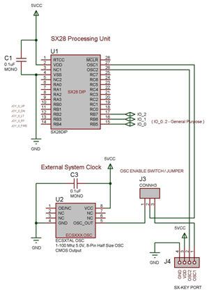
The SX 28 internal oscillator Is not that fast so an external oscillator can be hooked up to the processor as shown in the diagram to increase the operation cycles per second. (View)
View full Circuit Diagram | Comments | Reading(1212)
TV Pattern Generator (ZNA234E)
Published:2012/9/13 3:45:00 Author:Ecco | Keyword: TV Pattern, Generator

This Circuit uses the ZNA234E IC which makes available all the waveforms necessary to produce the crosshatch, dot and greyscale test patterns on a television screen. The composite video output can be injected directly into the video input of a receiver or used to drive a modulator for connection to the aerial socket.
Source: NEXT.GR (View)
View full Circuit Diagram | Comments | Reading(2284)
Astable/Monostable oscillator using 555 IC
Published:2012/9/13 3:44:00 Author:Ecco | Keyword: Astable/Monostable , oscillator , 555 IC

The 555 is a highly stable device for generating accurate time delays or oscillation. Aditional terminals are provided for triggering or resetting if desired. In the time delay (monostable) modeof operation the time is precisely controlled by one extrernal resistor and one capacitor. For stable operation as an oscillator, the free running frequency and the duty cycle are both accurately controlled with two external resistors and one capacitor.
Source: NEXT.GR (View)
View full Circuit Diagram | Comments | Reading(845)
Sound effects generator (UM3561)
Published:2012/9/12 21:10:00 Author:Ecco | Keyword: Sound effects generator
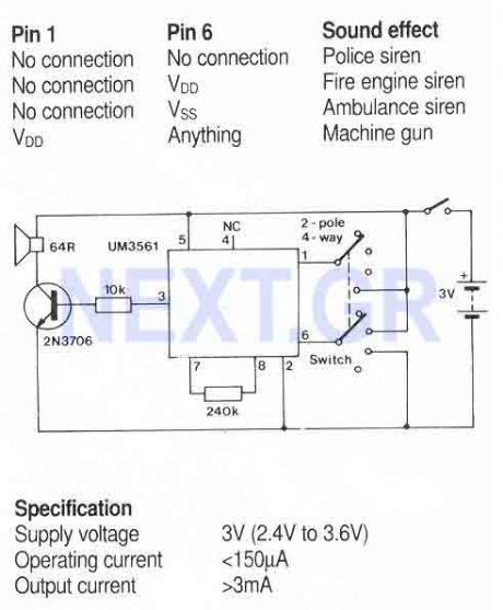
A simple sound generator IC that can produce four sound effects. Designed for use in toys, the effects are selected by varying the connections to pins1 and 6 as follows... (View)
View full Circuit Diagram | Comments | Reading(946)
| Pages:38/195 At 202122232425262728293031323334353637383940Under 20 |
Circuit Categories
power supply circuit
Amplifier Circuit
Basic Circuit
LED and Light Circuit
Sensor Circuit
Signal Processing
Electrical Equipment Circuit
Control Circuit
Remote Control Circuit
A/D-D/A Converter Circuit
Audio Circuit
Measuring and Test Circuit
Communication Circuit
Computer-Related Circuit
555 Circuit
Automotive Circuit
Repairing Circuit