
Signal Processing
Index 30
PLL FM Transmitters
Published:2012/11/15 0:31:00 Author:muriel | Keyword: PLL, FM , Transmitters
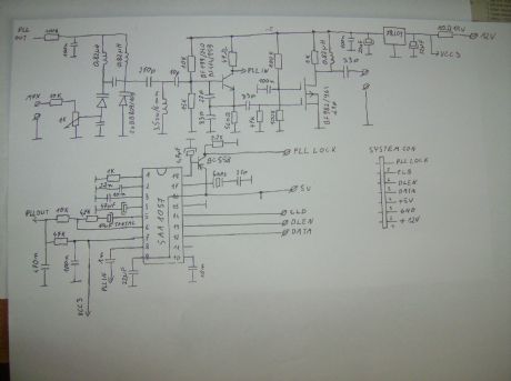
This is PLL FM Transmitter using SAA1057 chip. Transmitter can be operated from a PC through LPT port, or using a PC software as a driver. (View)
View full Circuit Diagram | Comments | Reading(2968)
PLL Exciter-2
Published:2012/11/15 0:30:00 Author:muriel | Keyword: PLL Exciter
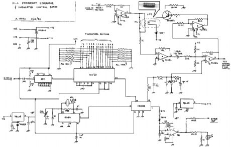
This is a PLL controller that works with the VCO/Modulator that I designed. Use these two modules together for a complete baseband-capable exciter unit. This PLL controller features a rock-stable crystal controlled reference, in conjunction with a programmable dividing network which allows the transmitter to be tuned in 100Khz steps from 79.9Mhz to 109.7Mhz by means of digital thumbwheel switches.
(View)
View full Circuit Diagram | Comments | Reading(2883)
PLL Exciter
Published:2012/11/15 0:29:00 Author:muriel | Keyword: PLL Exciter
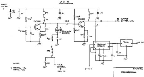
This is a PLL controller that works with the VCO/Modulator that I designed. Use these two modules together for a complete baseband-capable exciter unit. This PLL controller features a rock-stable crystal controlled reference, in conjunction with a programmable dividing network which allows the transmitter to be tuned in 100Khz steps from 79.9Mhz to 109.7Mhz by means of digital thumbwheel switches. (View)
View full Circuit Diagram | Comments | Reading(1119)
Phone Spy Transmitter
Published:2012/11/15 0:29:00 Author:muriel | Keyword: Phone, Spy, Transmitter
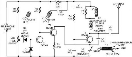
Here is a very simple telephone broadcaster transmitter which can be used to eavesdrop on a telephone conversation. The circuit can also be used as a wireless telephone amplifier. One important feature of this phone transmitter is that the circuit derives its power directly from the active telephone lines, and thus avoids use of any external battery or other power supplies.
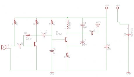
This not only saves a lot of space but also money. It consumes very low current from telephone lines without disturbing its performance. The phone bug transmitter is very tiny and can be built using a single -IC type veroboard that can be easily fitted inside a telephone connectin box of 3.75cm x 5cm. The spy phone transmitter consists of two sections, namely, automatic switching section and FM transmitter section. Spy phone transmitter circuit diagram Phone Spy Transmitter Automatic switching section comprises resistors R1 to R3, preset VR1, transistor T1 and T2, zener D2 and diode D1. Resistor R1, along with preset VR1, works as a voltage divider. When voltage across the telephone lines is 48V DC, the voltage available at wiper of preset VR1 ranges from 0 to 32V (adjustable). The switching voltage of the circuit depends on zener breakdown voltage and switching voltage of the transistor T1. Thus, if we adjust preset VR1 to get over 24.7 volts, it will cause the zener to breakdown and transistor T1 to conduc. As a result collector of transistor T1 will get pulled towards negative supply, to cut off transistor T2. At this stage, if you lift the handset of the telephone, the line voltage drops to about 11V and transistor T1 is cut off. As a result, T2 gets forward biased through R2 to provide a DC path for T3 used in the following FM transmitter section. The low-power FM transmitter section comprises oscillator transistor T3, coil L1 and a few other components. T3 works as a common-emitter RF oscillator, with T2 serving as an electronic 搊n/off� switch. The audio signal available across the telephone lines automatically modulates oscillator frequency via T2 along with its biasing R3. The modulated RF signal is fed to the antenna. The telephne conversation can be heard on an FM receiver remotely when it is tuned to the transmitter frequency. (View)
View full Circuit Diagram | Comments | Reading(1186)
Miniature FM Transmitter
Published:2012/11/15 0:28:00 Author:muriel | Keyword: Miniature, FM , Transmitter
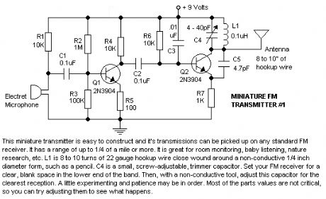
This miniature transmitter is easy to construct and it's transmissions can be picked up on any standard FM receiver. It has a range of up to 1/4 of a mile or more. It is great for room monitoring, baby listening, nature research, etc. L1 is 8 to 10 turns of 22 gauge hookup wire close wound around a non-conductive 1/4 inch diameter form, such as a pencil. C4 is a small, screw-adjustable, trimmer capacitor. Set your FM receiver for a clear, blank space in the lower end of the band. Then, with a non-conductive tool, adjust this capacitor for the clearest reception. A little experimenting and patience may be in order. Most of the parts' values are not critical, so you can try adjusting them to see what happens.
FM Transmitter Parts: R1, R4, R6 10K resistor R2 1Meg resistor R3 100K resistor R5 100 ohm resistor R7 1K resistor C1, C2 0.1uf capacitor C3 0.01uf capacitor C4 4-40pf variable capacitor C5 4.7pf capacitor Q1, Q2 2N3904 transistor L1 8-10 turns of 22gauge wire around non-conductive 1/4 diameter form Elec Mike Electret Mic (View)
View full Circuit Diagram | Comments | Reading(1783)
Mini FM Transmitter
Published:2012/11/15 0:27:00 Author:muriel | Keyword: Mini , FM , Transmitter
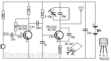
9 Volt battery operated simple Mini FM Transmitter. FM Transmitter is very simple, compact, and has transmission signal with a range of 100-150m, good sensitivity and low current consumption. Transmitter's schematic consists of a bass amplifier for the first transistor and the proper frequency generator in the second. FM Transmitter divided transitional capacitor that allows you to set up a cascade separately.
Transmitter PCB shows the value of all the details and transistors! Reel contains 5 turns enameled wires 0.35mm to send a diameter of 3.2mm (rod of the handle). Setting frequency boils down to the installation shown in the pattern of voltages through appropriate resistors, and then check the current consumption � it should be about 10mA antenna � a piece of wire 40cm. Here you can see the bug assembly factory performance. FM Transmitter uses very small PCB and some SMD resistors.
(View)
View full Circuit Diagram | Comments | Reading(3357)
Mini FM Radio Transmitter
Published:2012/11/15 0:27:00 Author:muriel | Keyword: Mini, FM, Radio, Transmitter
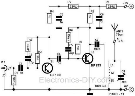
This small FM transmitter with a range of about 50 meters designed for hoby. With lots of mini-transmitters then you have a comprehensive, action-packed radio program. Due to the power supply via the USB port of a high frequency stability is achieved. Alternatively, the receiver, a battery 5 to 12 volts to operate.
Mini FM Radio Transmitter circuit with BF199. Tags: BF199, Mini fm radio Transmitter circuit, radio transmitter circuit, rc transmitter circuit, receiver circuit, rf transmitter circuit, small FM transmitter, transducer circuit, transistor circuit, video transmitter circuit, wireless transmitter circuit (View)
View full Circuit Diagram | Comments | Reading(1955)
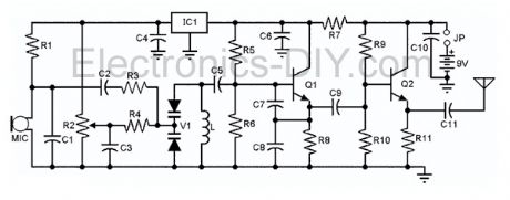
Micro Spy PLL FM Transmitter
Published:2012/11/15 0:26:00 Author:muriel | Keyword: Micro, Spy, PLL , FM, Transmitter
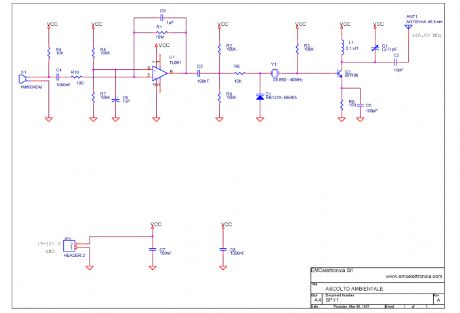
This micro spy PLL FM Transmitter transmits on the 160MHz frequency (if we use a 40MHz quartz) and therefore can be listened through a receiver tuned on this frequency. This circuit can be used to on various frequencies, for example on the FM band 88-108 just modifying some components, among which the quartz (25MHz). Voice is detected by an electret microphone, then it is amplified and filtered by U1 pass-band in order then to be modulated from the carrier section, where through the varicap diode it mixes with the frequency generated by the quartz, that guarantees an adapted stability. Practically the modulating voltage is obtained applying the audio signal to the resonating circuit varicap diode that determines the carrier oscillation. The carrier frequency (160 MHz) must be greater than the modulating frequency (300-3300 Hz) audio band. The transmission is on the fourth harmonic, therefore 160MHz, the oscillation frequency of the driver RF transistor Q1. A small calibration is allowed acting on the L1 inductance and the C1 Trimmer Capacitor. (View)
View full Circuit Diagram | Comments | Reading(1999)
LowPass Filter
Published:2012/11/15 0:23:00 Author:muriel | Keyword: LowPass Filter
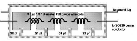
The schematic you find here comes from another site on the internet, but because it's on so many sites, we don't know who actually designed it. However it's a nice one. Capacitors: C1,C4 22pF cer. C2,C3 51pF cer. Coils: L1,L2,L3 #18 bus wire, 1/4 diameter, 3 turns * Form the leads from the capacitors as shown in the little figure below. Then solder them from the pad to the outside ground area. * Be sure that the turns from the coil are seperated by the same distance as the diameter of the wire * Form the leads from the coils as shown in the little figure below. Then solder them in place. * Place the filter in a metal box, with rf-connectors on both ends ( SO239(=PL259), BNC or N-connectors) (View)
View full Circuit Diagram | Comments | Reading(1880)
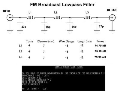
Low Pass Filter For FM 88-108 MHz
Published:2012/11/15 0:22:00 Author:muriel | Keyword: Low Pass , Filter, FM , 88-108 MHz
View full Circuit Diagram | Comments | Reading(2761)
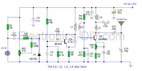
Long Range FM Transmitter Circuit
Published:2012/11/15 0:21:00 Author:muriel | Keyword: Long Range , FM , Transmitter Circuit
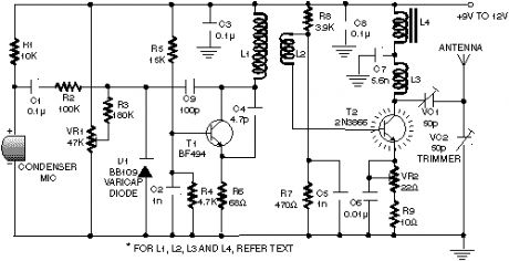
This circuit is a circuit diagram fm transmitter. This circuit is somewhat different from the previous fm transmitter circuit. Transmitter circuit described here has the additional RF power amplifier stage, after the oscillator stage, to increase the power output of 200-250 milliwatts. With a good matching 50-ohm ground plane antenna or multi-element yagi antenna, this transmitter can provide a good enough signal strength to a distance of about 2 kilometers.
The circuit built around transistor T1 (BF494) is the basic low-power variable-frequency VHF oscillator. A varicap diode circuit is included to change the frequency of the transmitter and to provide frequency modulation by audio signals. The output of the oscillator is about 50 milliwatts. Transistor T2 (2N3866) forms a VHF-class power amplifier. This increases the oscillator signals� power four to five times. Thus, 200-250 milliwatts of power produced at the collector of transistor T2. For better results, assemble the circuit on a good quality glass epoxy board and house the transmitter in the case of aluminum. Shield the oscillator stage using aluminum sheets. Transistor T2 must be mounted on the heat sink. Do not switch on the transmitter without a matching antenna. Adjust both trimmers (VC1 and VC2) for maximum transmission power. Adjust potentiometer VR1 to set the fundamental frequency near 100 MHz. Coil winding details are given below: L1 � 4 changes of 20 SWG wire close wound over 8mm diameter plastic former. L2 � 2 changes of 24 SWG wire near top end of L1. (Note: There is no core (ie air core) is used to coil on top) L3 � 7 changed from 24 SWG wire close wound with 4mm diameter air core. L4 � 7 changed from 24 SWG wire-wound on ferrite beads (choking) Potentiometer VR1 is used to change the fundamental frequency whereas potentiometer VR2 is used as power control. (View)
View full Circuit Diagram | Comments | Reading(1188)
Long Range FM Transmitter-2
Published:2012/11/15 0:21:00 Author:muriel | Keyword: Long Range, FM , Transmitter
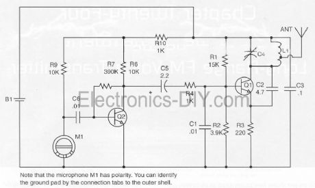
Part List: R1_______15K R2_______3K9 R3_______220R R4,R5____1K R6,R9____10K R7_______390K C1,C6____0.01uF C2_______4.7pF C3_______0.1uF C4_______6-35pf trimmer cap C5_______2.2uF B1_______3V L1_______Coil winding (see below) Q1,Q2____PN2222 M1_______Special FET bypassed microphone Assemble L1 : Form L1 by tightly wrapping eight turns of #16 bus wire on a #8 wood screw. Produces an eight-turn coil with an inner diameter of approximately 0.135 inches and lenght of about 0.625 inches. Insert in the proper hole and solder as shown.
(View)
View full Circuit Diagram | Comments | Reading(1274)
Long Range FM Transmitter
Published:2012/11/15 0:19:00 Author:muriel | Keyword: Long Range, FM , Transmitter
The power output of many transmitter circuits are very low because no power amplifier stages are incorporated. The transmitter circuit described here has an extra RF power amplifier stage, after the oscillator stage, to raise the power output to 200-250 milliwatts. With a good matching 50-ohm ground plane antenna or multi-element Yagi antenna, this transmitter can provide reasonably good signal strength up to a distance of about 2 kilometres. The circuit built around transistor T1 (BF494) is a basic low-power variable-frequency VHF oscillator. A varicap diode circuit is included to change the frequency of the transmitter and to provide frequency modulation by audio signals. The output of the oscillator is about 50 milliwatts. Transistor T2 (2N3866) forms a VHF-class A power amplifier. It boosts the oscillator signal power four to five times. Thus, 200-250 milliwatts of power is generated at the collector of transistor T2.
For better results, assemble the circuit on a good-quality glass epoxy board and house the transmitter inside an aluminum case. Shield the oscillator stage using an aluminum sheet. Coil winding details are given below: L1 - 4 turns of 20 SWG wire close wound over 8mm diameter plastic former. L2 - 2 turns of 24 SWG wire near top end of L1. (Note: No core (i.e. air core) is used for the above coils) L3 - 7 turns of 24 SWG wire close wound with 4mm diameter air core. L4 - 7 turns of 24 SWG wire-wound on a ferrite bead (as choke) Potentiometer VR1 is used to vary the fundamental frequency whereas potentiometer VR2 is used as power control. For hum-free operation, operate the transmitter on a 12V rechargeable battery pack of 10 x 1.2-volt Ni-Cd cells. Transistor T2 must be mounted on a heat sink. Do not switch on the transmitter without a matching antenna. Adjust both trimmers (VC1 and VC2) for maximum transmission power. Adjust potentiometer VR1 to set the fundamental frequency near 100 MHz. This transmitter should only be used for educational purposes. Regular transmission using such a transmitter without a license is illegal in India.
(View)
View full Circuit Diagram | Comments | Reading(1699)
iPod FM Transmitter
Published:2012/11/14 0:57:00 Author:muriel | Keyword: iPod , FM Transmitter
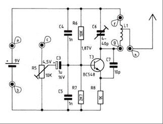
Here are instructions for building your own ipod FM radio transmitter. It works quite easy, there is a power switch on the bottom to turn it on and tune your radio and transmitter to the right frequency. For the antenna you can use a copper wire of 70 cm. The range of this FM transmitter is about 100 to 150 meters (500 feet). With R5 you can adjust the input signal and with C6 you can tune your frequency. Transmitter is supplied by 9V battery.
iPod FM Transmitter parts list: Transistor: T3 ...............................2N2219a Capacitor: C3 ...............................1 μF/16 V C4,C5 .........................1 nF ker. C6 trimmer capacitor...4-40 pF C7 ...............................10 pF ker. Resistor: R5 Trimmer.................10 kΩ R6 .............................. 10 kΩ R7 ...............................2,7 kΩ R8................................1 kΩ Spool L1: Use a 10 cm long Silver wire. The diameter inside the spool should be 3 mm. 7 winds total Length of the spool should be 15 mm (f-g) The antenna is connected to the spool at 3mm from f a: + 9volt b: ground c: audio in Ground your audio input to b For the antenna you can use a copper wire (70 cm) With R5 you can adjust the input signal and with C6 you can tune your frequency.
(View)
View full Circuit Diagram | Comments | Reading(2592)
FM Transmitter with Varactor Diode Tuning
Published:2012/11/14 0:54:00 Author:muriel | Keyword: FM Transmitter , Varactor Diode Tuning
Presented here is a low-power FM transmitter with varactor diode tuning using surface-mount devices (SMD) that will be received with a standard FM radio. Soldering surface mounted devices is not so hard and actually is quite easy. There are many designs for small FM transmitters but they have some problems. First, you need an audio amplifier to get enough modulation. Second, the antenna is attached directly to the collector. Third, the coil L must be wound by hand and adjusted by stretching. It all ads with a weak signal that tends to drift in frequency. In contrast the transmitter schematic we present here eliminates some of those problems, using varactor diode for tuning and modulation, givin great sensitivity without an audio amplifier. (View)
View full Circuit Diagram | Comments | Reading(2139)
FM Transmitter with 2N2218
Published:2012/11/14 0:54:00 Author:muriel | Keyword: FM Transmitter, 2N2218
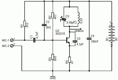
Here's simple FM transmitter circuit using medium power 2N2218 transistor. Micropohone is of electret type that connects to two input terminals and the antenna should be a copper wire from 15 to 40 cm. Below is schematic circuit of the fm transmitter. (View)
View full Circuit Diagram | Comments | Reading(2749)
FM Transmitter Circuit
Published:2012/11/14 0:53:00 Author:muriel | Keyword: FM , Transmitter Circuit
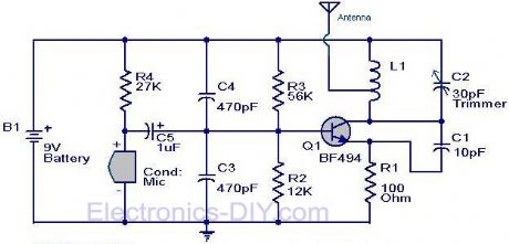
Here is the circuit diagram of the simple FM transmitter using a transistor. Great performance or range is not guaranteed here, because this is an elementary design. General purpose radio frequency transistor BF 494 (Q1) is used here for obtaining FM modulation. A condenser mic is used here to pickup the sound.The condenser mic converts the sound to electrical variations and this variations are fed to the base of Q1 , which performs the amplification as well as modulation.The capacitor C2 and L1 determines the frequency of transmission.The circuit can be powered from a 9V transistor radio battery.
Notes The coil L1 can be made by winding 8 turns of 1mm thick enamel coated copper wire on a ball pen refill. The coil should be tapped at the center for connecting the antenna. A 30 cm wire can be used as an antenna. Remember! This circuit is an elementary circuit.No good performance or range is not guaranteed.Ideal for demo applications only.I got only 8 meter range with some decent sound quality. Battery is strictly recommended because mains powered supply may induce additional noise. (View)
View full Circuit Diagram | Comments | Reading(1290)
FM Transmitter Bug
Published:2012/11/14 0:52:00 Author:muriel | Keyword: FM , Transmitter Bug
The goal of this project is for me personally to learn a little more about fm transmitters and fm bug making (may the HAM radio gods bless me in this pursuit). The ideal outcome of this project is a very small and full functional FM transmitter that we can stick into a plastic mint box. In order to be able to build this, we'll have to learn a lot about amplifiers, LC oscillators, mixers, antennas and FM. This project assumes you're already comfortable build your own PCB boards. If you're not please take a look at the homemade pcb's tutorial before you continue. It will help you out a lot.
So we've already seen mint can MP3 players and mint can amplifiers for guitars and tons of other projects, why not an FM bug transmitter? Well for starters, a tin can would be the worst place to put an fm transmitter! Luckily I stumbled upon this plastic mint box and thought...why not? Two transistor FM transmitters and FM bug circuits are all over the internet and they all share a common design that will be followed in this project as well. The reason I'm not trying to invent something new here is simply because FM transmitters have been redesigned to death. Why not instead have some fun with it? (View)
View full Circuit Diagram | Comments | Reading(912)
FM Telephone Transmitter
Published:2012/11/14 0:51:00 Author:muriel | Keyword: FM, Telephone , Transmitter
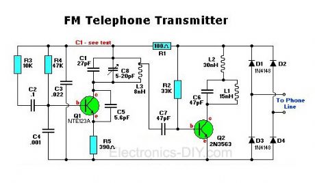
The FM telephone circuit is built on a PC board that is so small it can easily be fitted inside the housing of a telephone making it an instant pseudo-speak earphone. This FM transmitter circuit connects in series with telephone line, steals power from it, and transmits both sides of the conversation to an FM radio tuned between 90 and 95 MHz. (View)
View full Circuit Diagram | Comments | Reading(1895)
FM Broadcast Transmitter
Published:2012/11/14 0:50:00 Author:muriel | Keyword: FM, Broadcast, Transmitter
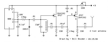
This FM Broadcast Transmitter circuit will transmit a continuous audio tone on the FM broadcast band (88-108 MHz) which could used for remote control or security purposes. Circuit draws about 30 mA from a 6-9 volt battery and can be received to about 100 yards. A 555 timer is used to produce the tone (about 600 Hz) which frequency modulates a Hartley oscillator. A second JFET transistor buffer stage is used to isolate the oscillator from the antenna so that the antenna position and length has less effect on the frequency. Fine frequency adjustment can be made by adjusting the 200 ohm resistor in series with the battery. Oscillator frequency is set by a 5 turn tapped inductor and 13 pF capacitor.
The inductor was wound around a #8 X 32 bolt (about 3/16 diameter) and then removed by unscrewing the bolt. The inductor was then streached to about a 3/8 inch length and tapped near the center. The oscillator frequency should come out somewhere near the center of the band (98 MHz) and can be shifted higher or lower by slightly expanding or compressing the inductor. A small signal diode (1N914 or 1N4148) is used as a varactor diode so that the total capacity in parallel with the inductor varies slightly at the audio rate thus causing the oscillator frequency to change at the audio rate (600 Hz). The ramping waveform at pins 2 and 6 of the timer is applied to the reversed biased diode through a large (1 Meg) resistor so that the capacitance of the diode changes as the ramping voltage changes thus altering the frequency of the tank circuit. Alternately, an audio signal could be applied to the 1 Meg resistor to modulate the oscillator but it may require an additional pullup resistor to reverse bias the diode. The N channel JFET transistors used should be high frequency VHF or UHF types (Radio Shack #276-2062 MPF102) or similar.
(View)
View full Circuit Diagram | Comments | Reading(936)
| Pages:30/195 At 202122232425262728293031323334353637383940Under 20 |
Circuit Categories
power supply circuit
Amplifier Circuit
Basic Circuit
LED and Light Circuit
Sensor Circuit
Signal Processing
Electrical Equipment Circuit
Control Circuit
Remote Control Circuit
A/D-D/A Converter Circuit
Audio Circuit
Measuring and Test Circuit
Communication Circuit
Computer-Related Circuit
555 Circuit
Automotive Circuit
Repairing Circuit