
Signal Processing
Index 22
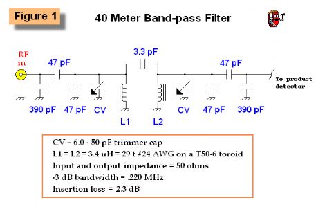
Double Tuned Band-pass Filter
Published:2012/12/27 0:59:00 Author:muriel | Keyword: Double , Tuned , Band-pass Filter
View full Circuit Diagram | Comments | Reading(2380)
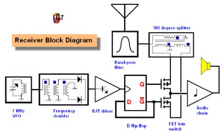
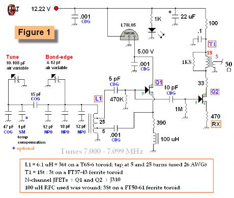
K7LR Memorial Receiver
Published:2012/12/27 0:58:00 Author:muriel | Keyword: K7LR , Memorial Receiver
View full Circuit Diagram | Comments | Reading(800)
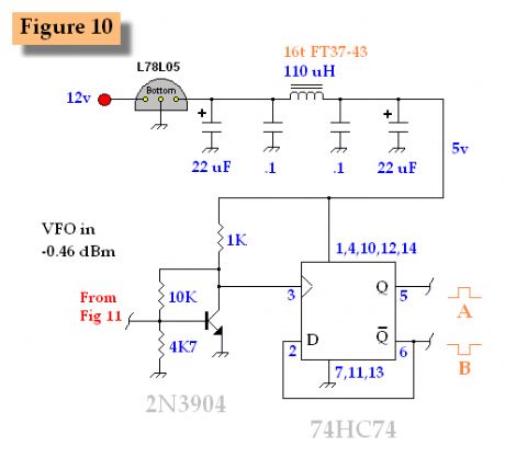
D Flip-Flop 2
Published:2012/12/27 0:56:00 Author:muriel | Keyword: D Flip-Flop
View full Circuit Diagram | Comments | Reading(697)
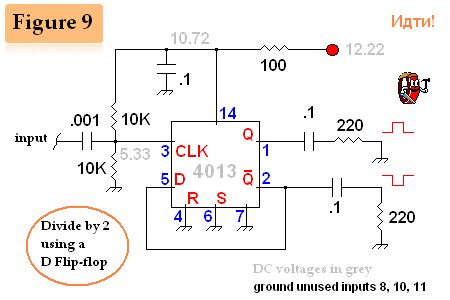
D Flip-Flop
Published:2012/12/27 0:56:00 Author:muriel | Keyword: D Flip-Flop
View full Circuit Diagram | Comments | Reading(1046)
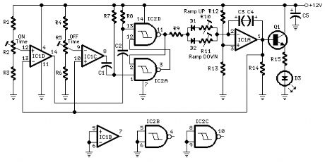
Fine Control SuperBright LED Pulser
Published:2012/12/23 21:01:00 Author:muriel | Keyword: Fine Control, SuperBright LED Pulser
View full Circuit Diagram | Comments | Reading(678)
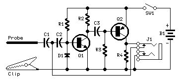
Pulse-Generator & Signal-Tracer
Published:2012/12/21 21:44:00 Author:muriel | Keyword: Pulse-Generator, Signal-Tracer
View full Circuit Diagram | Comments | Reading(985)
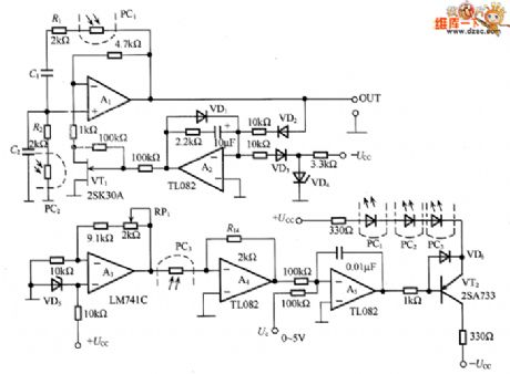
8 ~ 12MHz voltage controlled oscillator circuit diagram with stable output amplitude
Published:2012/12/21 1:44:00 Author:Ecco | Keyword: 8 ~ 12MHz , voltage controlled oscillator , stable output amplitude

In the circuit, VT2 controls the collector current of VT1, therefore, the oscillation amplitude of VT1 is very stable. VT4 output signal is converted into a DC signal by VD2 detector, here is the automatic gain controlling state, so that the DC voltage is kept constant. RP1's midpoint voltage is - 0.6V, and the current holding in R1 and R2 is equal, thereby controlling the output amplitude constant value. Oscillation frequency is decided by L1, C2, varactor diode VD1 and distributed capacitor. Uo output voltage is 2V, the frequency is 8 ~ 12MHz signal.
(View)
View full Circuit Diagram | Comments | Reading(1732)
Low distortion Wien bridge oscillator circuit diagram
Published:2012/12/21 3:08:00 Author:Ecco | Keyword: Low distortion , Wien bridge, oscillator
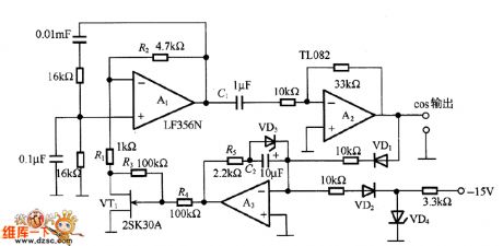
The oscillation principle is that when the loop phase shift amount is an integer multiple of 0 ° or 360 °, the loop gain is greater than 1, the circuit starts oscillation. If the oscillation is increased, the circuit will be saturated, therefore it needs an amplitude stabilization circuit. In the circuit, the amplitude stabilization circuit uses a junction FET (VT1) drain - source resistor to connect with R1 in series to make R2 / 2 = 4.7kΩ / 2 = 2.35kΩ.
(View)
View full Circuit Diagram | Comments | Reading(2516)
Simple Square wave Generator
Published:2012/12/20 20:57:00 Author:muriel | Keyword: Simple , Square wave, Generator
View full Circuit Diagram | Comments | Reading(0)
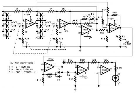
Low-distortion Audio-range Oscillator
Published:2012/12/20 20:57:00 Author:muriel | Keyword: Low-distortion , Audio-range , Oscillator
View full Circuit Diagram | Comments | Reading(1273)
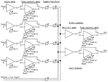
Portable Mixer
Published:2012/12/19 21:43:00 Author:muriel | Keyword: Portable Mixer
View full Circuit Diagram | Comments | Reading(731)
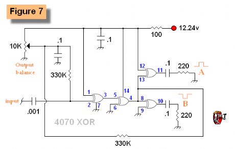
Exclusive-OR gates with split output 2
Published:2012/12/17 20:35:00 Author:muriel | Keyword: Exclusive-OR gates , split output
View full Circuit Diagram | Comments | Reading(601)
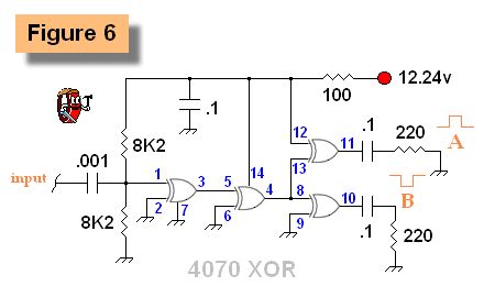
Exclusive-OR gates with split output
Published:2012/12/17 20:35:00 Author:muriel | Keyword: Exclusive-OR gates , split output
View full Circuit Diagram | Comments | Reading(663)
symmetrical AC waveform
Published:2012/12/17 20:33:00 Author:muriel | Keyword: symmetrical AC waveform
View full Circuit Diagram | Comments | Reading(716)
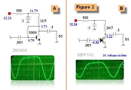
JFET switch (B) output waveform
Published:2012/12/17 20:32:00 Author:muriel | Keyword: JFET switch (B), output waveform
View full Circuit Diagram | Comments | Reading(916)
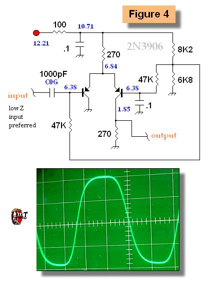
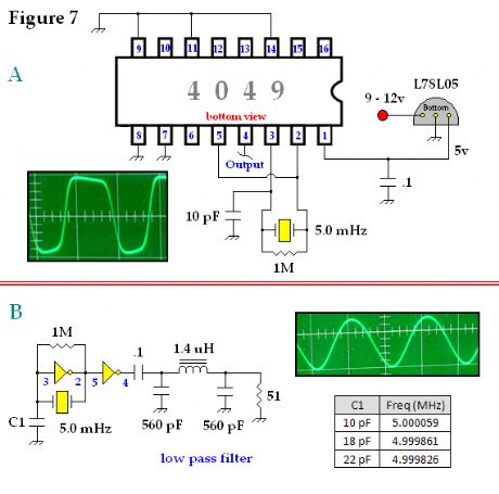
Shaping a Sine Wave Into a Square Wave
Published:2012/12/17 20:32:00 Author:muriel | Keyword: Sine Wave, Square Wave
View full Circuit Diagram | Comments | Reading(1098)
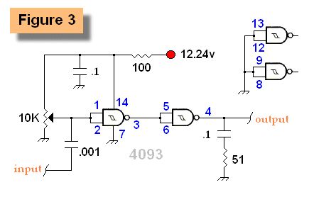
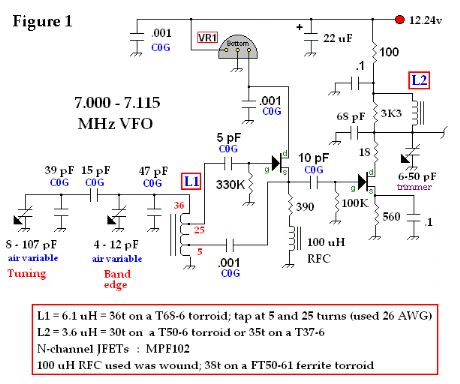
Base VFO
Published:2012/12/17 20:31:00 Author:muriel | Keyword: Base VFO
View full Circuit Diagram | Comments | Reading(1287)
Scanning oscillator circuit diagram
Published:2012/12/17 3:42:00 Author:Ecco | Keyword: Scanning oscillator
This circuit is composed of RC Wien bridge oscillator and voltage controlled resistor, wherein the Wien bridge circuit is available for RC circuit with a selected frequency, and A1 magnification is about three times, loop gain is 1. The output of A2 is half wave rectified by VD2, then it is comparing with the reference current generated by VD4 to make integrating, thereby controlling the VT1's gate voltage and changing the resistance between the drain - source.
(View)
View full Circuit Diagram | Comments | Reading(1146)
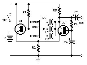
Variable Frequency Oscillator
Published:2012/12/16 21:07:00 Author:muriel | Keyword: Variable Frequency, Oscillator
View full Circuit Diagram | Comments | Reading(1281)
Crystal Oscillator
Published:2012/12/16 21:05:00 Author:muriel | Keyword: Crystal Oscillator
View full Circuit Diagram | Comments | Reading(4176)
| Pages:22/195 At 202122232425262728293031323334353637383940Under 20 |
Circuit Categories
power supply circuit
Amplifier Circuit
Basic Circuit
LED and Light Circuit
Sensor Circuit
Signal Processing
Electrical Equipment Circuit
Control Circuit
Remote Control Circuit
A/D-D/A Converter Circuit
Audio Circuit
Measuring and Test Circuit
Communication Circuit
Computer-Related Circuit
555 Circuit
Automotive Circuit
Repairing Circuit