
Communication Circuit
Index 21
ONE_TUBE_REGENERATIVE_AM_RECEIVER
Published:2009/6/24 4:24:00 Author:May
Suitable for AM reception and as a simple radio project, this circuit uses a single tube as a regenerative detector. (View)
View full Circuit Diagram | Comments | Reading(0)
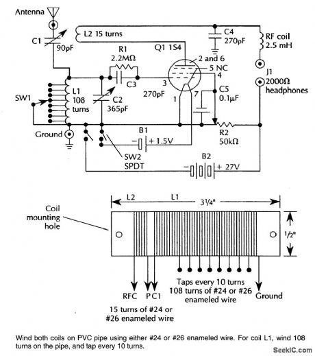
ONE_TUBE_REGENERATIVE_SW_RECEIVER
Published:2009/6/24 4:23:00 Author:May

A 154 tube is used in a regenerative detector circuit. Details for coils are shown and frequency range can be shifted within 1.5 to 20 MHz by proportionally adjusting the number of tums on coils (View)
View full Circuit Diagram | Comments | Reading(1178)
NINE_BAND_SHORTWAVE_RECEIVER
Published:2009/6/24 4:18:00 Author:May
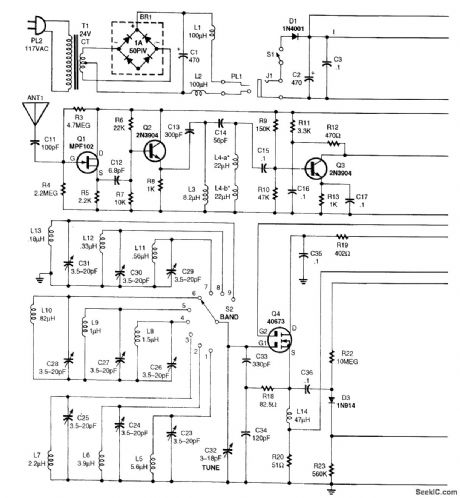
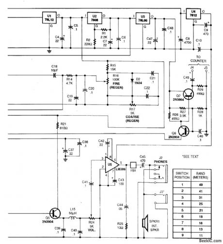
Dual-gate MOSFET Q4 is used as a regenerative amplifier in this circuit.An active antenna feeds the signal to Q4,and a short whip antenna is adequate.Derector Q5 feeds volume control R24,and audio amplifier U5,an LM386.The frequency is 49 to 11 meters in nine bands (6 to 27 MHz). (View)
View full Circuit Diagram | Comments | Reading(1758)
118_TO_136_MHz_AIRCRAFT_RECEIVER
Published:2009/6/24 3:50:00 Author:May
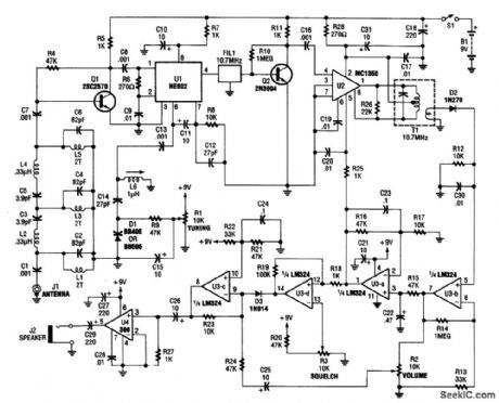
This recelver covers the 118-to 136-MHz AM aviation band It has a 10 7-MHz IF amplifier. L1,L3,and L5 are 1 1/2 turns of#24wire FIL1 is a 10 7-MHz ceramic filter.IF bandwidth will be about 250 kHz. (View)
View full Circuit Diagram | Comments | Reading(2608)
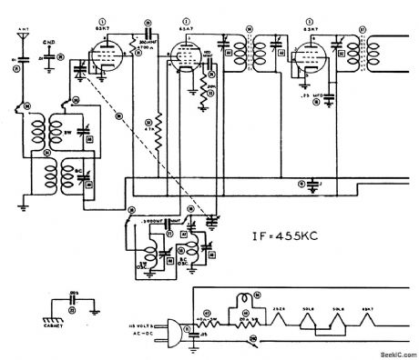
SHORTWAVE_RECEIVER
Published:2009/6/24 3:45:00 Author:May
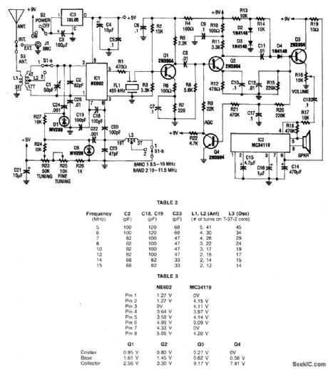
This receiver covers 8.5 to 11.5 MHz in two bands and has a sensitivity of under 1 μV. Nn NE602 mixer feeds a 455-kHz IF amplifier (Q1 and Q2), detector D4, and audio amplifier IC2. Q4 serves as an AGC amplifier coil data is given in the table. The LO is varactor tuned. (View)
View full Circuit Diagram | Comments | Reading(0)
WWV_RECEIVER
Published:2009/6/24 3:43:00 Author:May
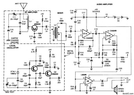
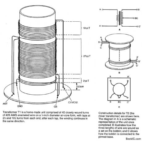
RF amplifier Q3 feeds diode mixer D1-D2 and Q1-Q2 provide 10-MHz L.O. injection to D1 through T1 and T2,U1A,U1B and U2 are audio amplifiers.Details of T1 and T2 are shown. (View)
View full Circuit Diagram | Comments | Reading(0)
ac/dc_VACUUM_TUBE_AM_AND_SHORTWAVE_RECEIVER
Published:2009/6/24 3:38:00 Author:May

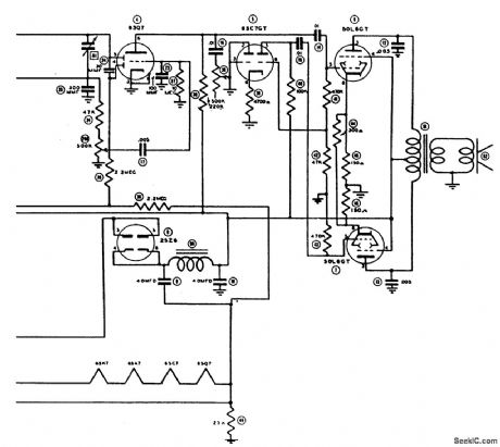
This circuit was used in a World War II vintage AM/SW(6 to 18 MHz)recelver and shows typical circuits used in recelvers at that time. (View)
View full Circuit Diagram | Comments | Reading(0)
AM_RADIO
Published:2009/6/24 3:31:00 Author:May
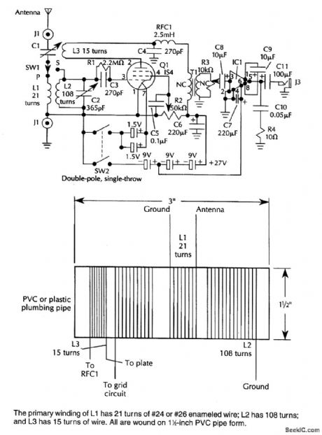
A IS4 regenerative detector feeds an LM386 audio IC (IC1). 1.5-V D cells and three 9-V batteries are used for a power supply. (View)
View full Circuit Diagram | Comments | Reading(0)
MUSICAL_INSTRUMENT_DIGITAL_INTERFACEMIDIRECEIVER
Published:2009/6/23 22:54:00 Author:May
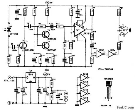
Receiver photodiode SFH250 is used to convert optical data pulses at 32.5 Kb to electrical signals. Buffer T2 feeds the signals to cascade amplifier T3-T4, then to op amp IC4, and buffers IC5-f and IC5-e. IC6 supplies 9 V for the circuit. (View)
View full Circuit Diagram | Comments | Reading(0)
PREAMP_TRANSMIT_RECEIVE_SEQUENCER
Published:2009/6/23 1:41:00 Author:May
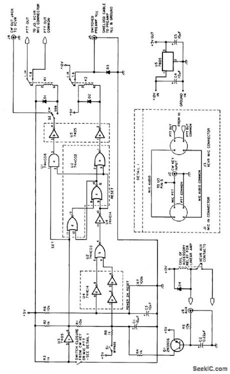
This circuit is useful in amateur radio VHF and UHF work where a mast-mounted antenna preamp is used for receiving. The kit controls T-R switching and change-over relay sequencing so that high RE levels are prevented from accidentally being applied to the preamplifier during switching intervals. (View)
View full Circuit Diagram | Comments | Reading(0)
DIRECT_CONVERSION_7_MHz_RECEIVER
Published:2009/6/23 Author:May
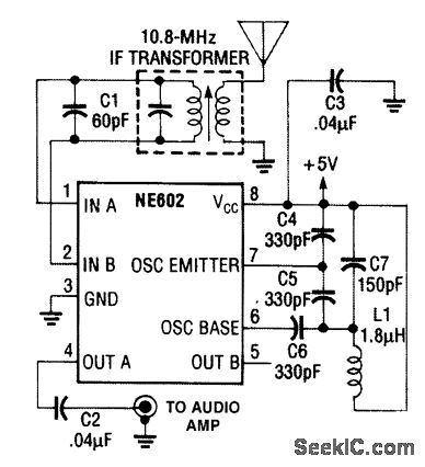
An NE602 is used to mix signals in the 7-MFlz range with an LO and to produce audio output. (View)
View full Circuit Diagram | Comments | Reading(1665)
SIMPLE_HF_RECEIVE_CONVERTER
Published:2009/6/22 23:38:00 Author:May
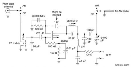
Designed for CB reception, this crystal-controlled converter uses one 40820 dual-gate MOSFET. The circuit will work with any crystal either 3rd overtone or fundamental, over 1 to 50 MHz. (View)
View full Circuit Diagram | Comments | Reading(0)
HUM_REDUCER_FOR_DIRECT_CONVERSION_RECEIVERS
Published:2009/6/22 23:20:00 Author:May
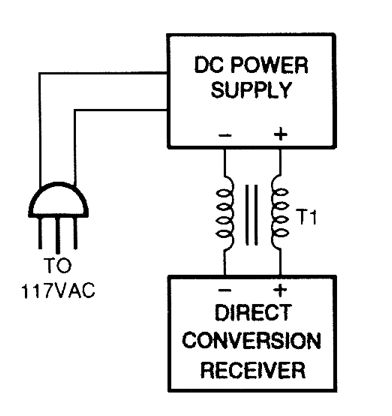

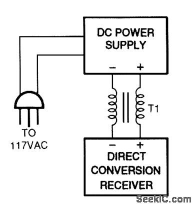
One cure for ac power line hum and ripple (caused by leakage current) is to use a well-regulated and filtered 9- to 18-Vdc power supply with a balancing choke (T1 in this illustration) between the power supply and the DCR. (View)
View full Circuit Diagram | Comments | Reading(0)
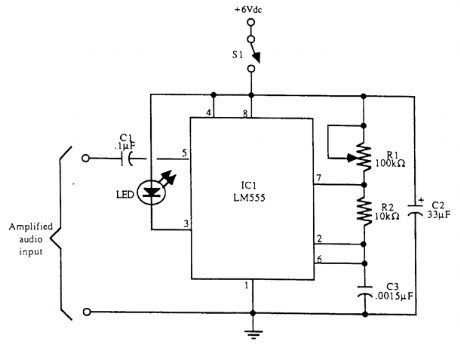
PLL_IR_LASER_LIGHT_RECEIVER
Published:2009/6/22 22:29:00 Author:May
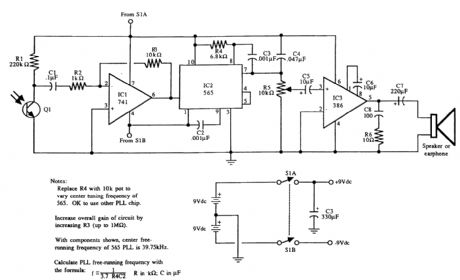
Circuit schematics for the 555-based PLL laser light PFM receiver. Although R4 is shown as a resistor, you might want to sub-stitute it with a 10-kΩ precision potentiometer so that you can dial in the center frequency of the transmitter. Experiment with the value of C1 for the best high-frequency response. Notice that circuit is functionally identical to the laser light detector/receiver shown in the figure, but with the addition of the 565. (View)
View full Circuit Diagram | Comments | Reading(3562)
LASER_DIODE_TRANSMITTER
Published:2009/6/22 22:27:00 Author:May
View full Circuit Diagram | Comments | Reading(1154)
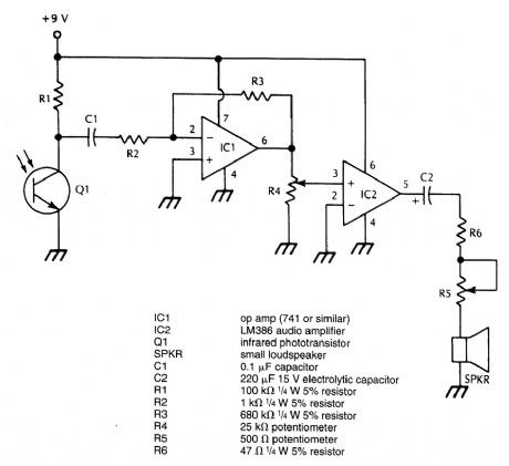
Optical communication receive circuit diagram
Published:2011/7/21 3:06:00 Author:Ecco | Keyword: Optical communication receive
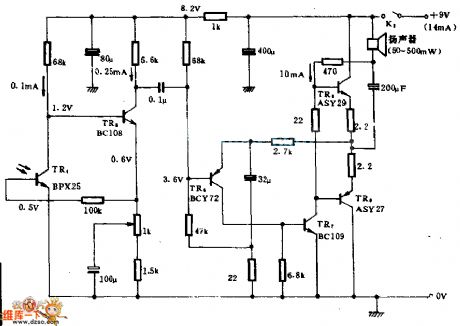
When the phototube is exposured by the light that emits from light-emitting diode modulated by proper infrared transmitter(the transmitter is far away from 137.2 m). The circuit can give the maximum output of 500 mW to 15 Ω speakers. The system is applicable to installing electronic wire wireways in inconvenient situation and useing under the sistuation of wavelength in about 0.9 μ m. (View)
View full Circuit Diagram | Comments | Reading(1705)
AUDIBLE_OUTPUT_INFRARED_RECEIVER
Published:2009/6/19 4:24:00 Author:May
This receiver is designed to demodulate amplitude-modulated (AM) IR light beams and will drive a loudspeaker. R5 is an auxiliary volume control and it could be omitted. Q1 should be suitably mounted and shielded from stray light pickup. (View)
View full Circuit Diagram | Comments | Reading(1189)
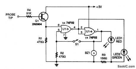
SINGLE_TONE_INFRARED_RECEIVER
Published:2009/6/19 4:23:00 Author:May

Phototransistor Q3 acts as a sensor that detects modulated IR energy. Q1 is an amplifier and U1 is a tone decoder. LED1 lights on reception of an IR signal with proper tone modulation. (View)
View full Circuit Diagram | Comments | Reading(1119)
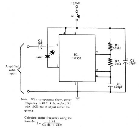
PULSE_FREQUENCY_MODULATED_IR_TRANSMITTER
Published:2009/6/19 4:21:00 Author:May
Schematic diagram for the pulse frequency-modulated LED transmitter. Adjust the frequency by rotating R1. With components shown, the frequency range is between 8 and 48 kHz. (View)
View full Circuit Diagram | Comments | Reading(1885)
WIRELESS_IR_HEADPHONE_RECEIVER
Published:2009/6/19 4:20:00 Author:May
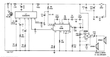
A photodiode D1 feeds high gain IR remote control preamp IC, a CA3237E. U2 is a PLL FM de-tector tuned to around 100 kHz. The detector output is amplified by U3 and it can drive a speaker or a set of headphones. (View)
View full Circuit Diagram | Comments | Reading(3805)
| Pages:21/32 At 20212223242526272829303132 |
Circuit Categories
power supply circuit
Amplifier Circuit
Basic Circuit
LED and Light Circuit
Sensor Circuit
Signal Processing
Electrical Equipment Circuit
Control Circuit
Remote Control Circuit
A/D-D/A Converter Circuit
Audio Circuit
Measuring and Test Circuit
Communication Circuit
Computer-Related Circuit
555 Circuit
Automotive Circuit
Repairing Circuit