
Communication Circuit
Index 3
BMW solenoid valve solenoid valve position circuit diagram
Published:2014/1/6 19:50:00 Author: | Keyword: BMW solenoid valve solenoid valve position circuit diagram,
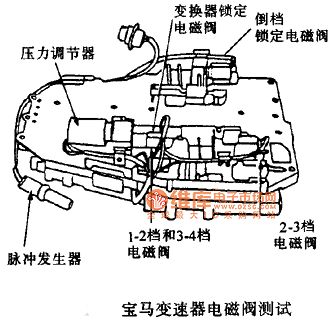
BMW solenoid valve solenoid valve position circuit diagram
(View)
View full Circuit Diagram | Comments | Reading(937)
BMW BMW3 series A4S 55-310 - r pin transmission circuit diagram
Published:2014/1/6 19:48:00 Author: | Keyword: BMW BMW3 series A4S 55-310 - r pin transmission circuit diagram,
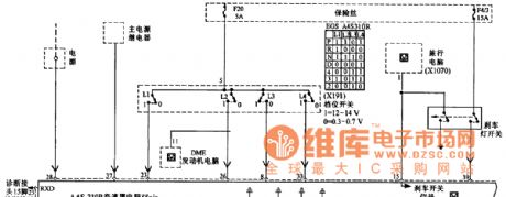
BMW BMW3 series A4S 55-310 - r pin transmission circuit diagram
(View)
View full Circuit Diagram | Comments | Reading(937)
BMW 97 328 I wiper washing circuit diagram (Canada)
Published:2013/12/17 1:59:00 Author: | Keyword: BMW 97 328 I wiper washing circuit diagram (Canada),
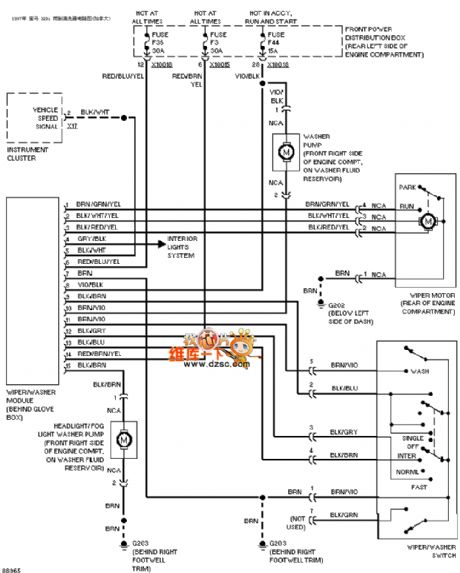
BMW 97 328 I wiper washing circuit diagram (Canada) as shown below:
(View)
View full Circuit Diagram | Comments | Reading(1019)
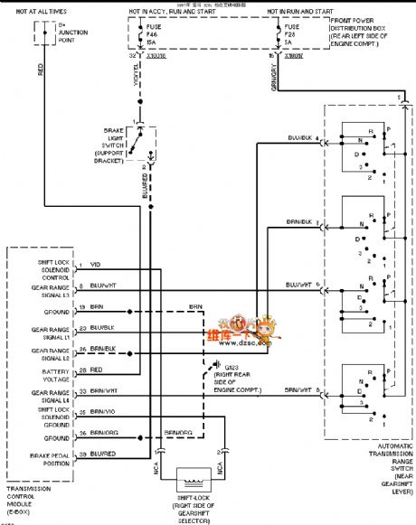
BMW 97 328 I transmission circuit diagram
Published:2013/12/17 1:46:00 Author: | Keyword: BMW 97 328 I transmission circuit diagram,
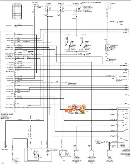
BMW 97 328 I transmission circuit diagram as shown below:
(View)
View full Circuit Diagram | Comments | Reading(934)
BMW 97 328 I visor circuit diagram
Published:2013/12/16 2:12:00 Author: | Keyword: BMW 97 328 I visor circuit diagram,
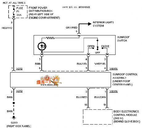
BMW 97 328 I visor circuit diagram as shown below:
(View)
View full Circuit Diagram | Comments | Reading(943)
BMW 97 328 I gear interlock circuit diagram
Published:2013/12/13 2:03:00 Author: | Keyword: BMW 97 328 I gear interlock circuit diagram ,
BMW 97 328 I gear interlock circuit diagram as shown below:
(View)
View full Circuit Diagram | Comments | Reading(1011)
BMW 97 328 I electric seat circuit diagram
Published:2013/12/13 1:58:00 Author: | Keyword: BMW 97 328 I electric seat circuit diagram,
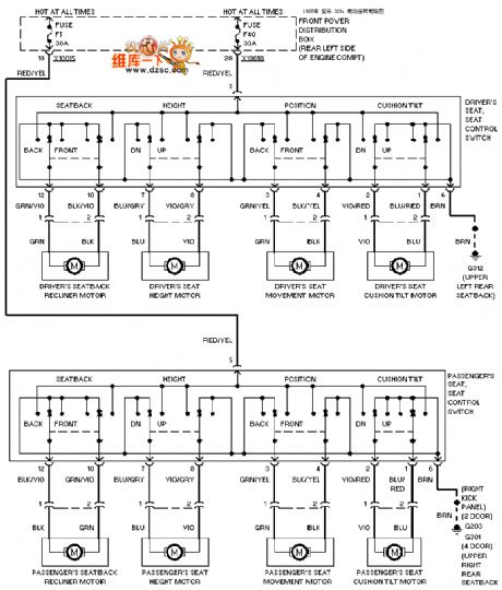
BMW 97 328 I electric seat circuit diagram as shown below:
(View)
View full Circuit Diagram | Comments | Reading(1194)
Mercedes-Benz 190E alarm system circuit diagram
Published:2013/12/10 1:27:00 Author: | Keyword: Mercedes-Benz 190E alarm system circuit diagram,
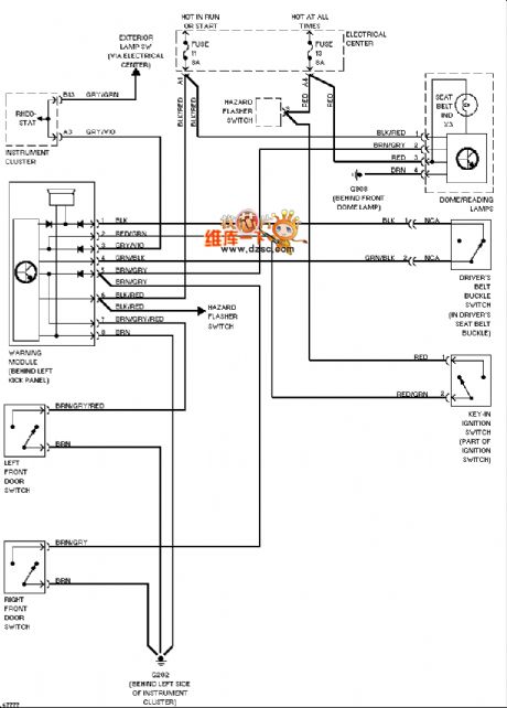
Mercedes-Benz 190E alarm system circuit diagram is shown below:
(View)
View full Circuit Diagram | Comments | Reading(2342)
Mercedes-Benz 190E starter circuit diagram
Published:2013/12/10 1:24:00 Author: | Keyword: Mercedes-Benz 190E starter circuit diagram,
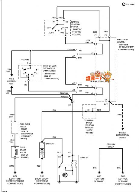
Mercedes-Benz 190E starter circuit diagram is shown below:
(View)
View full Circuit Diagram | Comments | Reading(4648)
Mercedes-Benz 190E electric windows circuit diagram
Published:2013/12/9 1:37:00 Author: | Keyword: Mercedes-Benz 190E electric windows circuit diagram,
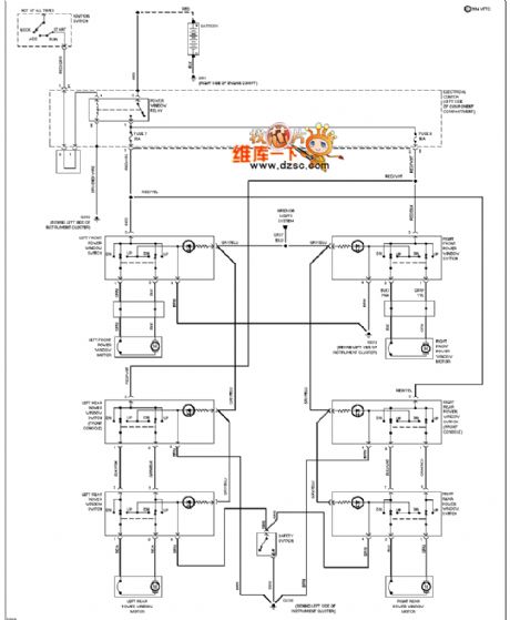
Mercedes-Benz 190E electric windows circuit diagram is shown below:
(View)
View full Circuit Diagram | Comments | Reading(3037)
Mercedes-Benz 190E electric mirrors Diagram
Published:2013/12/9 1:34:00 Author: | Keyword: Mercedes-Benz 190E electric mirrors Diagram,
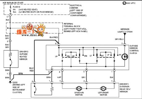
Mercedes-Benz 190E electric mirrors circuit diagram is shown below:
(View)
View full Circuit Diagram | Comments | Reading(2217)
Mercedes-Benz 190E power supply circuit
Published:2013/12/9 1:28:00 Author: | Keyword: Mercedes-Benz 190E power supply circuit,
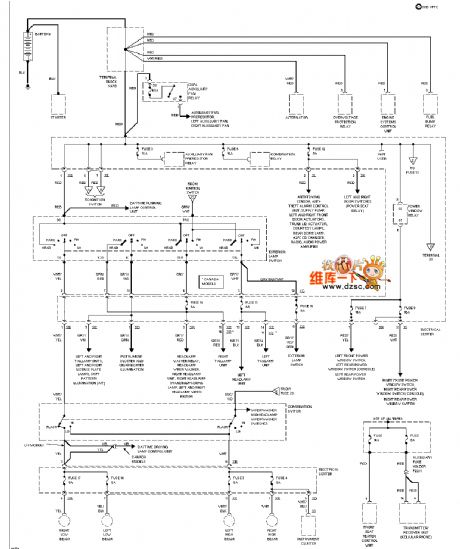
Mercedes-Benz 190E power supply circuit are as follows:
(View)
View full Circuit Diagram | Comments | Reading(991)
Mercedes-Benz 190E seat adjustment circuit diagram
Published:2013/12/9 1:25:00 Author: | Keyword: Mercedes-Benz 190E seat adjustment circuit diagram,
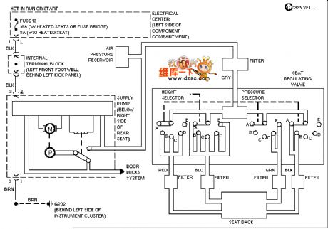
Mercedes-Benz 190E seat adjustment circuit diagram is shown below:
(View)
View full Circuit Diagram | Comments | Reading(1381)
Mercedes 190E dashboard schematics
Published:2013/12/9 1:17:00 Author: | Keyword: Mercedes 190E dashboard schematics,
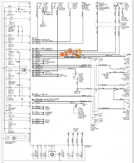
Mercedes 190E dashboard diagram is shown below:
(View)
View full Circuit Diagram | Comments | Reading(1460)
Mercedes-Benz 190E Schematic defogger
Published:2013/12/8 20:52:00 Author:lynne | Keyword: Mercedes-Benz 190E Schematic defogger,
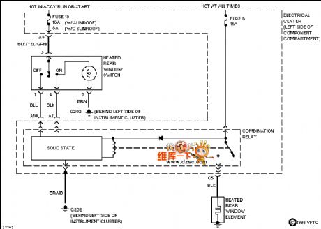
Mercedes-Benz 190E defogger circuit diagram is shown below:
(View)
View full Circuit Diagram | Comments | Reading(1202)
Basic Low Power AM transmitter Circuit
Published:2013/11/12 19:59:00 Author:lynne | Keyword: Basic Low Power AM transmitter
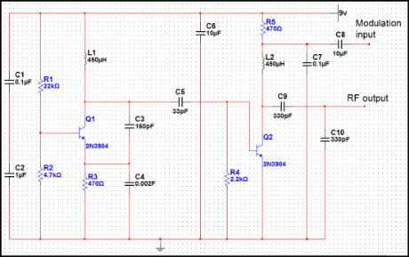
This transmitteris basic but allows transmission of audio to an AM radio. It consists of an RFoscillator operating in the AM broadcast band, together with a modulator stage,which mixes the incoming audio and the RF. A signal appears on the output, whichhas an AM component that can be picked up on a nearby AM radio receiver.
The transmitter consists ofoscillator stage Q1 and modulator/buffer stage Q2. Q1 is biased via R1, R2, and R3.L1, C3, and C4 form the tank circuit with feedback network C3-C4 providing feedbackto the emitter of Q1. RF voltage at the junction of C3 and L1 drives buffer/modulator stage Q2. Q2 is biased by base current produced by RF rectification in thebase emitter junction of Q2. C6 is an RF and AF bypass capacitor. C9, C10, and L2form the tank circuit for the collector of Q2. RF is taken from the junction of C9 andC10 and fed to ashort-wireantenna. Audio is fed to modulator Q2 via C8 and isolationresistor R5 and mixes with the RF signal in the collector circuit of Q2, producinga signal that has sum and difference frequencies if the RF carrier and AF input along with the carrier signal.
An AM signal appears atthe collector of Q2. Audio with an RMS voltage equal to about 0.7 times the collectorvoltage of Q2 is needed for full modulation of the output.Because of the high level of audio needed, the modulation obtained from this circuitis somewhat limited with conventional audio sources because several volts ofaudio into a few hundred ohms is needed. The circuit demonstrates the principle ofan AM transmitter, however, and with a suitable audio drive level, produces a well modulatedAM signal. (View)
View full Circuit Diagram | Comments | Reading(1247)
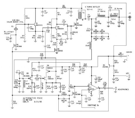
The AP-80 An Alternative Pixie
Published:2013/5/2 22:23:00 Author:muriel | Keyword: AP-80 An, Alternative Pixie
View full Circuit Diagram | Comments | Reading(1425)
Simple 75M SSB rig with PTT
Published:2013/5/2 22:22:00 Author:muriel | Keyword: Simple 75M , SSB rig , PTT
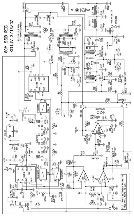
The output of the Tx mixer is buffered by a 2N4401 emitter follower to drive the low impedance input side of a 10.7 MHz IF transformer. The transformer is returned to 75 meters by an additional, external 330 p cap. A second IF transformer is used to make a double tuned band pass filter, although for 75 meters. (View)
View full Circuit Diagram | Comments | Reading(1481)
PBUS communication bus for connecting microcontroller-based devices
Published:2013/5/2 22:20:00 Author:muriel | Keyword: PBUS communication bus, connecting microcontroller-based devices

View full Circuit Diagram | Comments | Reading(983)
MIDI to RS232 Interface
Published:2013/5/2 22:19:00 Author:muriel | Keyword: MIDI to RS232 Interface

View full Circuit Diagram | Comments | Reading(1170)
| Pages:3/32 1234567891011121314151617181920Under 20 |
Circuit Categories
power supply circuit
Amplifier Circuit
Basic Circuit
LED and Light Circuit
Sensor Circuit
Signal Processing
Electrical Equipment Circuit
Control Circuit
Remote Control Circuit
A/D-D/A Converter Circuit
Audio Circuit
Measuring and Test Circuit
Communication Circuit
Computer-Related Circuit
555 Circuit
Automotive Circuit
Repairing Circuit