
Communication Circuit
Index 10
16_30_MHz_20_W_HIGH_GAIN_DRIVER
Published:2009/7/14 3:13:00 Author:May
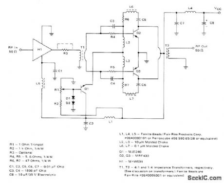
Broadband amplifier operating from 12-V supply uses Motorola MRF433 power transistors for class AB operation and MHW591 as predriver. For class A operation, power transistors should be MRF426. Q2 does not require heatsink because its peak dissipation is under 1 W. Power gain is 55 dB well beyond four-octave band of amplifier, and input VSWR is under 1.2.-H. 0. Granberg, Low-Distortion 1.6 to 30 MHz SSB Drivel Designs, Motorola, Phoenix, AZ, 1977, AN-779, p7.
(View)
View full Circuit Diagram | Comments | Reading(2184)
400_W__PUSH_PULL
Published:2009/7/14 2:57:00 Author:May
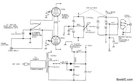
Grounded-grid linear push-pull power amplifier requires no neutralizing, uses balun for push-pull excitation, and can feed either one-band or all-band tuner for amateur radio bands. Balun is 8 turns of 72-ohm twin-line wound on Amidon 2-inch toroid core to give 4:1 ratio. Article covers construction and adjustment.-B Baird, Build This Inexpensive 400 Watt Amplifier, 73Magazine,Holiday issue 1976, p 22-23. (View)
View full Circuit Diagram | Comments | Reading(1382)
140_180_MHz_AT_30_W
Published:2009/7/14 2:55:00 Author:May
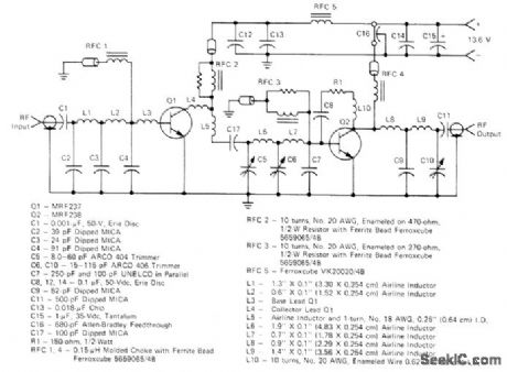
Two-transistor amplifier provides gain of over 20 dB for VHF marine, amateur, and commercial transmitters. Trimmers are tuned for peak output at center frequency in 10-MHz range of interest. Will operate into 30:1 mismatch without damage.-H. Burger and T. Bishop, Two VHF Highband Gain Blocks Form 20-dB, 30-Watt Amplifier Chain, Motorola, Phoenix, AZ, 1975, EB-53. (View)
View full Circuit Diagram | Comments | Reading(2402)
COLOR_BAR_GENERATOR
Published:2009/7/15 5:15:00 Author:Jessie
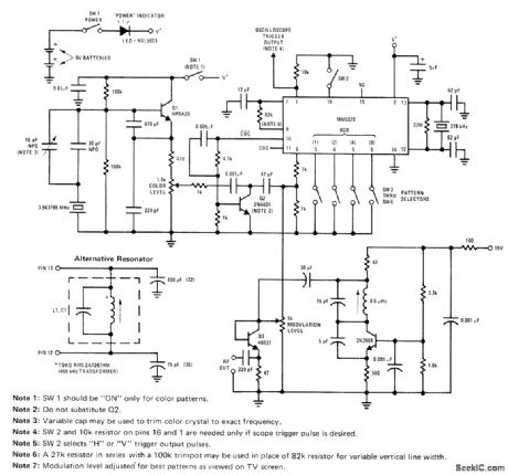
National MM5322 chip forms complete dot-bar and color hue generation system. Chip divides internal crystal-controlled oscillator frequency to provide timing, sync, and video information required for aligning color TV receivers. Composite video output serves for complete black-and-white dot-bar operation to give variety of screen patterns. Separate output is provided for precise gating of 3.56-MHz color bursts.- MOS/LSI Databook, National Semiconductor, Santa Clara, CA, 1977, p 4.18-4-22. (View)
View full Circuit Diagram | Comments | Reading(0)
GENERAL_PURPOSE_VIDEO_SWITCH
Published:2009/7/15 5:12:00 Author:Jessie
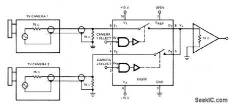
When used for switching TV cameras.DG200 CMOS analog switch provides 45-dB isolation at 10 MHz between on and off cameras,Insertion loss of switches 0.5 dB, For greater isolation、use additional analog switch in each camera line.-Analog Switches and Their Applications ” Siliconix. Santa Clara,CA,1976.p 7-70. (View)
View full Circuit Diagram | Comments | Reading(1830)
INTERLACED_SYNC
Published:2009/7/15 22:14:00 Author:Jessie
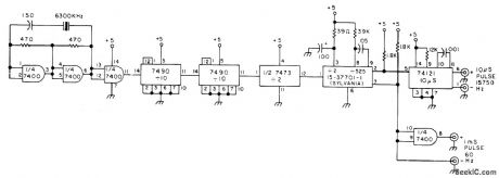
Uses Sylvania 15-37701-1 IC made by Texas Instruments for 1974 Sylvania color TVs, where it serves to generate sync signals whenever off-the-air sync is temporarily Lost. IC has divide-by-2, divide-by-25, and mono MVBR stages. Used in circuit shown to provide interlaced sync for black and white amateur TV camera, Required 31.5-kHz input is obtained from 6300-kHz crystal oscillator and three flip-flops that divide by 200 With 74121 mono and 7400 gate connected as shown, interlaced sync outputs are obtained.-R. Suding, Master Sync Generator, 73 Magazine, July 1975, p 96. (View)
View full Circuit Diagram | Comments | Reading(1365)
TWO_CAMERA_VIDEO_SWITCH
Published:2009/7/15 22:12:00 Author:Jessie
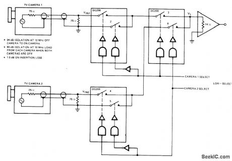
DG200 CMOS switches with built-in drivers provide 94-dB isolation at 10 MHz between on and off cameras. Desired camera is turned on by applying low logic level to select line for that camera.- Analog Switches and Their Applications, Siliconix, Santa Clara, CA, 1976, p 7-26. (View)
View full Circuit Diagram | Comments | Reading(1154)
RF_MODULATOR
Published:2009/7/15 22:11:00 Author:Jessie
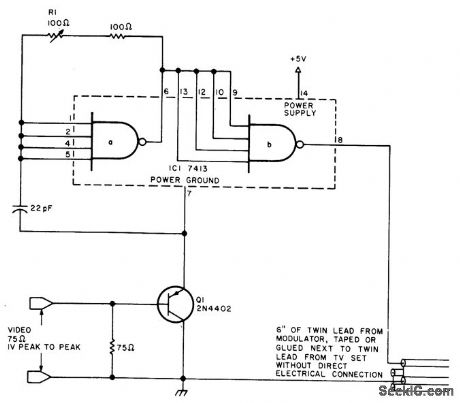
First section of free-running 7413 Schmitt-trigger oscillator runs at one-third of desired TV-channel carrier frequency (about 20 MHz for channel3) and drives buffer section whose output is square wave at oscillator fundamental. Q1 modulates RF output by varying effective supply voltage to IC. Since standard video is 1 V P-P, modulation depth is about 20% with 5-V supply. Capacitive connection is made to TV set, using short lengths of 300-ohm line after removing regular antenna leads from set used as experimental display terminal for microprocessor. R1 determines frequency of oscillation; ad just for best reception.-W, Banks, The Waterloo RF Modulator, BYTE, Jan. 1978, p94. (View)
View full Circuit Diagram | Comments | Reading(0)
HORIZONTAL_SYSTEM_FOR_19_INCH_COLOR
Published:2009/7/15 22:10:00 Author:Jessie
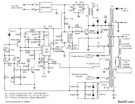
Self-regulating scan system includes short-circuit protection. Provides excellent high-voltage regulation at 25 kV. Vertical yoke current is also stabilized since it is powered from auxiliary fly-back winding. System consumes 30% less power than more conventional circuit using SCR half-wave regulated supply.-R. J. Valentine, A Self-Regulating Horizontal Scan System, Motorola, Phoenix, AZ, 1975, AN-750, p 7.
(View)
View full Circuit Diagram | Comments | Reading(1652)
S_SHAPED_RAMP
Published:2009/7/15 22:08:00 Author:Jessie
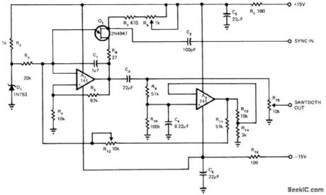
Developed for 60-Hz vertical deflection in high-resolution video display requiring highly linear ramp summed with second integral of ramp to give S shaping of deflection so sweep is linear on flat screen. Opamp A1 is connected as integrator that takes integral of constant voltage across zener D1. Period of integration is limited by UJT Q1 that resets integrating capacitor C1 when negative-going sync signal is applied to base 2 of Q1. Sawtooth linearity can be trimmed by adjusting ratio of R.4 to R5. Sync range is wide enough so external vertical hold can be eliminated. Amount of shaping can be adjusted with pot.-L. G. Smeins, S -Shaped Sawtooth Oscillator, EDN Magazine, Feb. 20, 1974, p 83 and 85. (View)
View full Circuit Diagram | Comments | Reading(1194)
SOUND__IF__SUBSYSTEM
Published:2009/7/15 22:06:00 Author:Jessie
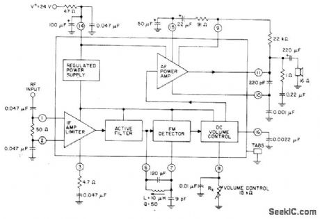
Single RCA CA1190GQ IC combines sound IF. FM detector. and complete audio amplifier for driving 8-16-or 32-ohm loudspeaker in TV receiver,Nominal power output is 3 W,Electronic volume control on chip provides improved taper with single 15K wire wound control,-“Linear Integrated Circuits and MOS/FETs,″RCA Solid-State Division. Somerville, NJ, 1977, p301 (View)
View full Circuit Diagram | Comments | Reading(1037)
MICROPROCESSOR_SSTV_INTERFACE
Published:2009/7/15 22:05:00 Author:Jessie
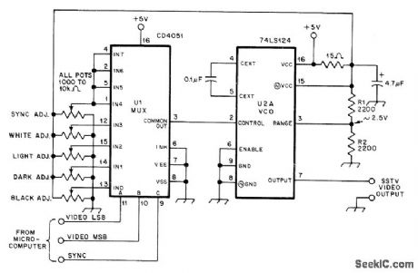
Digital-to-analog-to -frequency converter for slowscan television permits direct generation of simple graphic and alphameric characters by microprocessor, without use of camera, U1 is CD4051 CMOS analog multiplexor, and U2A is one section of 74LS124 TTL dual voltage-controlled oscillator. Picture format uses 64 different lines, repeated once to give total of 128 lines, with maximum of 64 different picture elements per horizontal line each having one of four shades of gray. Separate pot is provided for setting each of five different levels so VCO oscillates at proper frequencies: sync-1200 Hz; black-1500 Hz; dark-1767 Hz; light-2033 Hz; white-2300 Hz. Article covers operation in detail and gives flow diagrams for microprocessor subroutines required.-B. Sanderson, SSTV Pictures from Your Microcomputer, QST, Oct. 1978, p 25-29. (View)
View full Circuit Diagram | Comments | Reading(4740)
MODU_LATOR_MULTIPLIER
Published:2009/7/15 22:03:00 Author:Jessie
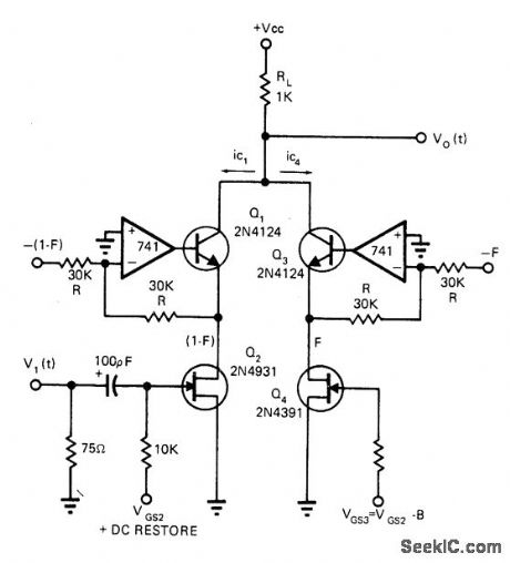
Balanced direct-coupled FET modulator/multiplier was developed for closed-circuit industrial color television system. Opamps handle modulation frequencies up to 1 MHz while providing linear response down to near zero modulation,-G. R. Shapiro, Analog Multipliers Offer Solutions to Video Modulation Problems, EDN Magazine, Sept. 1 1972, p 40-41. (View)
View full Circuit Diagram | Comments | Reading(1916)
CHROMA_SYSTEM
Published:2009/7/15 22:01:00 Author:Jessie
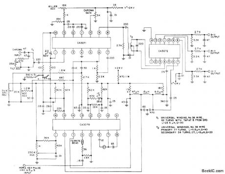
Uses RCA CA30T0 as subcarrier regenerator, CA3071 as chroma amplifier, and CA3072 as chroma demodulator, input can be taken from either first or second video stage of color TV receiver. Outputs from system are color difference signals for driving high-level amplifiers. Operates from single 24-V supply that should be maintained within 3 V. Only other requirement is 4-V 4.5-sμhorizontal keying pulse centered on color burst. Crystal oscillator generates 3.579545 MHz.- Linear Integrated Circuits and MOS/FET’s, RCA Solid State Division, Somerville, NJ, 1977, p 345-346. (View)
View full Circuit Diagram | Comments | Reading(2098)
VERTICAL_SYNC_SEPARATOR
Published:2009/7/15 21:58:00 Author:Jessie
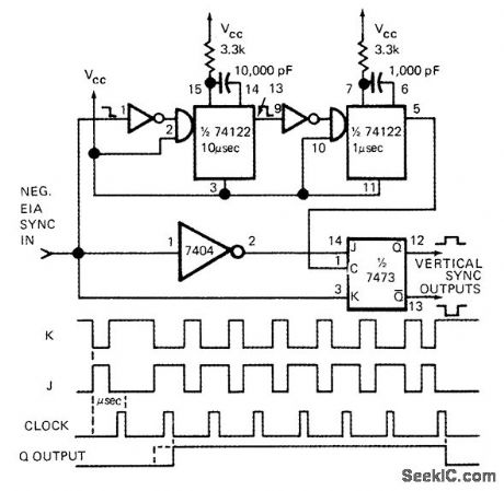
Arrangement uses controlled clocking sequence of JK flip-flop to detect presence of vertical sync interval in standard EIA television composite sync wave-form. Complementary sync waveforms J and K are fed to J and K inputs of 7473 flip-flop, which is clocked by 1-μs pulse that is delayed slightly longer than 10-μs horizontal sync interval. First clock pulse after 11-sμ interval changes flip-flop output Q to 1, where it stays for six clock periods before reverting to 0 state after vertical sync interval has passed.-W. G. Jung, Vertical Sync Separator Has No Integrating Network, EDN Magazine, Oct. 15, 1972, p 57. (View)
View full Circuit Diagram | Comments | Reading(3724)
DIGITAL_LINE_SELECTING_SWITCHES
Published:2009/7/15 21:57:00 Author:Jessie
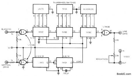
Three thumbwheel switches connected in binary mode control three 74192 counters、for selection of any desired line up to 999 in television field. Line-gate pulse injects into looped-through video for brightening selected line to make it visible on display. Circuit can also be used to determine exact number of active lines in each television field,Article describes operation in detail-H F,Stearns、Build a Thumb-wheel-Switched Television Line Selector, EDN Magazine, June 20,1976, p 124, (View)
View full Circuit Diagram | Comments | Reading(2494)
RGB_OUTPUT
Published:2009/7/15 21:55:00 Author:Jessie
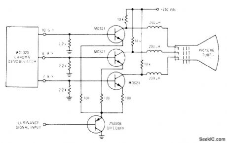
Motorola MDS21 high-voltages silicon transistors serve as out put stages for red, green, and blue channels of color TV receiver, to provide video amplitude requirements for color picture tube Transistors can be driven directly by most types of chroma demodulators,-″NPN Silicon Annular High Voltage Amplifier Transistors,″Motorola, Phoenix,AZ, 1978, DS 3364. (View)
View full Circuit Diagram | Comments | Reading(2484)
AFT_SUBSYSTEM
Published:2009/7/15 21:54:00 Author:Jessie
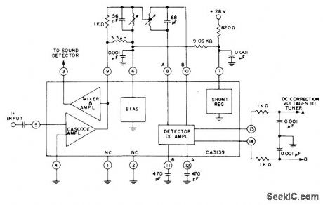
RCA CA3139 automatic fine tuning IC combined with intercarrier mixer/amplifier for color and monochrome receivers provides AFT voltage for tuner correction and amplified 4.5-MHz intercarrier sound signal for external FM sound detector of receiver. Input is taken from output of IF amplifier in receiver.- Linear Integrated Circuits and MOS/FET's, RCA Solid State Division, Somerville, NJ, 1977, p381. (View)
View full Circuit Diagram | Comments | Reading(1350)
VARIABLE_DELAY_UP_TO_7_μs
Published:2009/7/15 21:52:00 Author:Jessie

Used in television broadcasting when longer delay is required than can be achieved with passive elements for composite signal.-C M, Wong、Sync –Pulse Delay Wireless World,Feb. 1977、p46. (View)
View full Circuit Diagram | Comments | Reading(1136)
IR_TRANSMITTER_FOR_TV_SOUND
Published:2009/7/15 21:51:00 Author:Jessie
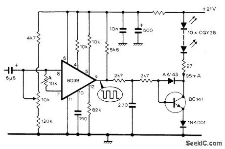
Mono audio output of TV receiver is fed to infrared modulator using Intersil 8038 IC and transistor.o provide pulse-frequency-modulated infrared output that can be picked up by compact receiver built into headphones S/N ratio is 58 dB in daylight in average living room having light walls and celling, but drops to 40 dB when receiver faces away from transmitter Used in German TV receivers displayed at 1975 Berlin Exhibition.-International Radio and Television Exhibition Wireless World Nov .1975, p 521-524 and 539. (View)
View full Circuit Diagram | Comments | Reading(2079)
| Pages:10/32 1234567891011121314151617181920Under 20 |
Circuit Categories
power supply circuit
Amplifier Circuit
Basic Circuit
LED and Light Circuit
Sensor Circuit
Signal Processing
Electrical Equipment Circuit
Control Circuit
Remote Control Circuit
A/D-D/A Converter Circuit
Audio Circuit
Measuring and Test Circuit
Communication Circuit
Computer-Related Circuit
555 Circuit
Automotive Circuit
Repairing Circuit