
Communication Circuit
Index 4
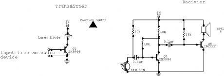
Laser Communication System electronic circuit diagram
Published:2013/4/1 3:19:00 Author:Ecco | Keyword: Laser Communication System
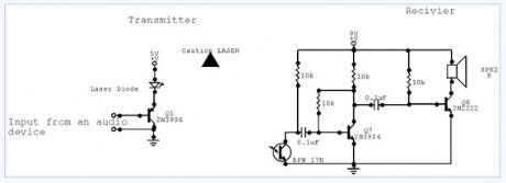
This is a simple Laser communication system. It can transmit and receive signal from any audio device.Communication distance is few meters. All components are not critical. Transistor 2N2222 may be on the coolrib. Laser diode is from laser pointer.
(View)
View full Circuit Diagram | Comments | Reading(2345)
Intercommunication-intercom electronic circuit diagram
Published:2013/4/1 3:18:00 Author:Ecco | Keyword: Intercommunication-intercom
View full Circuit Diagram | Comments | Reading(1488)
The House Finch Direct Conversion Tube Receiver
Published:2013/3/7 3:14:00 Author:Ecco | Keyword: House Finch, Direct Conversion Tube , Receiver

After building the Little Chickadee 6U8A vacuum tube 80 meter CW transmitter project, your author decided that it would be a good idea to build a companion 80 meter tube CW receiver. A direct-conversion design seemed like a good approach since it is fairly simple and is effective for receiving morse code. Not wanting to reinvent the wheel, the Internet was searched for vacuum tube direct conversion designs. Surprisingly, no other projects were found. The online projects that were found were either solid state designs or regenerative tube circuits.
Nature abhors a vacuum, but not necessarily a vacuum tube so this project was born. Of course, designing something new with vacuum tubes is not an entirely rational pursuit. Rationalizations aside, tube projects are fun, nostalgic and they glow in the dark. This project was a lot more difficult to complete than originally anticipated, but solving the many problems was certainly educational. Those who copy this design should have a much easier time getting the circuit running. It should be farily straightforward to adapt this design to other HF ham bands by changing the resonant sections in the front end filter and oscillator.
The 6U8A audio amp project was already functioning nicely and was perfect for the audio amplifier stage in a communications receiver. The 6U8A seemed like a good choice for the mixer and oscillator circuits. In fact, that's how the 6U8A is usually used. One can think of the 6U8A as a vacuum tube equivalent (sort of) of the popular NE602 IC. The first version of this receiver used just two 6U8A tubes, it worked (barely), but there was a need for additional audio gain and isolation between the antenna and the mixer. The 6C4 preamp tube and the 6BA6 RF amplifier tubes were added to solve these problems.
The receiver is divided into three physical sections, 1: the RF filter and amplifier, 2: the mixer, oscillator and audio filters and 3: the audio amplifier. A few extra grid bias resistors and filament hum cancelation resistors were added so that the individual sections can be disconnected and operated in a stand-alone mode. This also allows the sections to be used as stand-alone modules for other projects. An external power supply provides 6.3VAC for the filaments and 250VDC for the B+ supply, the supply can be shared between this receiver and the companion Little Chickadee transmitter.
(View)
View full Circuit Diagram | Comments | Reading(3391)
Simple Phone Tap
Published:2012/12/12 20:58:00 Author:muriel | Keyword: Simple Phone Tap
View full Circuit Diagram | Comments | Reading(1318)
Phone Busy Indicator
Published:2012/12/12 20:55:00 Author:muriel | Keyword: Phone Busy Indicator
View full Circuit Diagram | Comments | Reading(1279)
FM Telephone Bug
Published:2012/12/12 20:55:00 Author:muriel | Keyword: FM Telephone Bug
View full Circuit Diagram | Comments | Reading(0)
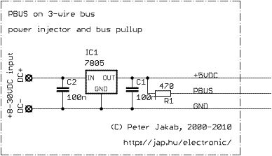
PBUS communication bus
Published:2012/12/6 1:18:00 Author:muriel | Keyword: PBUS communication bus
View full Circuit Diagram | Comments | Reading(1286)
Laser Communication System
Published:2012/12/3 0:49:00 Author:muriel | Keyword: Laser Communication System
View full Circuit Diagram | Comments | Reading(1527)
R5000 Computer Interface
Published:2012/11/21 2:06:00 Author:muriel | Keyword: R5000 , Computer Interface
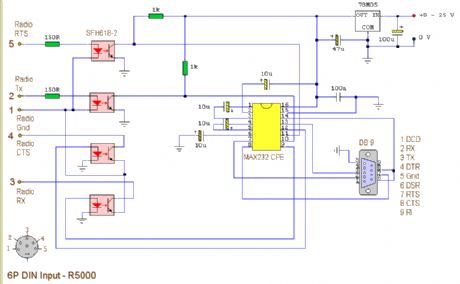
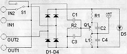
This circuit is a modified version of an original interface on QSL Net. It is a fully isolated interface allowing computer control of the Trio/Kenwood R5000 receiver. Separate software is needed to control the receiver. (View)
View full Circuit Diagram | Comments | Reading(1862)
Basic radio transmission circuit with surface acoustic wave resonator SAW
Published:2012/11/15 21:03:00 Author:Ecco | Keyword: Basic radio transmission , surface acoustic wave, resonator , SAW
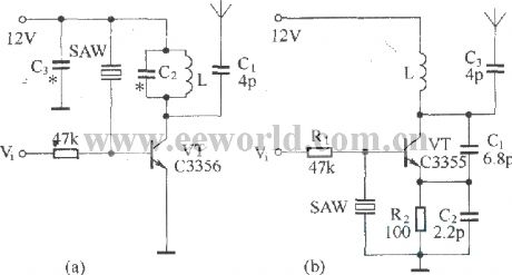
Figure (a) shows a basic circuit of the transistor UHF radio transmitter with surface acoustic wave resonator (SAW), and the SAW is used as a positive feedback element connected between the transistor VT base and LC network in parallel. Figure (b) shows another basic transistor UHF radio transmitter circuit with the surface acoustic wave resonator, in this circuit, SAW is connected between the transistor's base and emitter; the phase relationship between them is 180 degree.
(View)
View full Circuit Diagram | Comments | Reading(6201)
Light Fence Security Beeper
Published:2012/9/24 22:22:00 Author:muriel | Keyword: Light Fence,Security,Beeper
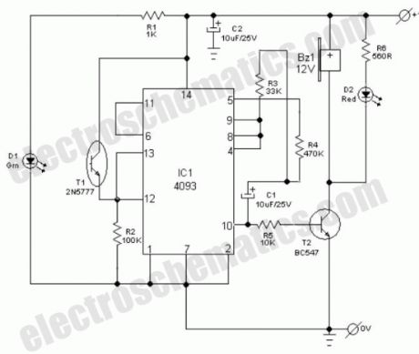
General purpose hobby circuit of a simple light fence security beeper is presented here. This circuit can be used as a door alarm, gate alarm, pathway alarm, etc. Any 12 Volt dc power supply can power the whole circuit.Working of this circuit is straight forward. In standby mode photo transistor T1 receives light from the green LED (D1) and T1 conducts to disable the gated low-frequency astable built around IC1(4093).When this light path is interrupted by any object in the path, T1 stops conducting and IC1 is switched by the low level at its input point (pins 12&13). As a result the piezo-buzzer starts beeping at a slow rate determined by the in circuit values of R3, R4 & C1. Red LED (D2) is a visual warning indicator.With the help of suitable reflector and lens assembly, length of the light path can be increased. A minimum of 1 to 2 metres is possible with a high-bright green LED as D1. A laser pointer can also be used as the light source.
Light Fence Alarm Circuit Schematic
(View)
View full Circuit Diagram | Comments | Reading(2726)
Basic low power AM transmitter
Published:2012/9/18 21:26:00 Author:Ecco | Keyword: Basic, low power , AM transmitter
This transmitter?is basic but allows transmission of audio to an AM radio. It consists of an RF?oscillator operating in the AM broadcast band, together with a modulator stage,?which mixes the incoming audio and the RF. A signal appears on the output, which?has an AM component that can be picked up on a nearby AM radio receiver.
The transmitter consists of?oscillator stage Q1 and modulator/buffer stage Q2. Q1 is biased via R1, R2, and R3.?L1, C3, and C4 form the tank circuit with feedback network C3-C4 providing feedback?to the emitter of Q1. RF voltage at the junction of C3 and L1 drives buffer/modulator stage Q2. Q2 is biased by base current produced by RF rectification in the?base emitter junction of Q2. C6 is an RF and AF bypass capacitor. C9, C10, and L2?form the tank circuit for the collector of Q2. RF is taken from the junction of C9 and?C10 and fed to a?short-wire?antenna. Audio is fed to modulator Q2 via C8 and isolation?resistor R5 and mixes with the RF signal in the collector circuit of Q2, producing?a signal that has sum and difference frequencies if the RF carrier and AF input ?along with the carrier signal.
An AM signal appears at?the collector of Q2. Audio with an RMS voltage equal to about 0.7 times the collector?voltage of Q2 is needed for full modulation of the output.?Because of the high level of audio needed, the modulation obtained from this circuit?is somewhat limited with conventional audio sources because several volts of?audio into a few hundred ohms is needed. The circuit demonstrates the principle of?an AM transmitter, however, and with a suitable audio drive level, produces a well modulated?AM signal.5 Responses to “Basic low power AM transmitter”
(View)
View full Circuit Diagram | Comments | Reading(1993)
Wireless Keylogger circuit
Published:2012/9/16 20:37:00 Author:Ecco | Keyword: Wireless Keylogger
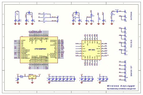
The Wireless Keylogger consists of two main building blocks: the transmitter, and the receiver. The actual keylogging takes place in the transmitter, which is in fact a PS/2 hardware keylogger, with a built-in 2.4 GHz wireless module. Captured keystroke data is transmitted through the radio-link in real-time, rather than getting stored. The receiver on the other hand, is a wireless acquisition unit with a USB interface. All keystroke data received from the transmitter is sent to the host computer via USB. From the software side, this data is available through a virtual COM port, allowing any terminal client to be used for visualizing keystroke data. (View)
View full Circuit Diagram | Comments | Reading(0)
2 Watts FM transmitter
Published:2012/9/13 20:52:00 Author:Ecco | Keyword: 2 Watts, FM transmitter
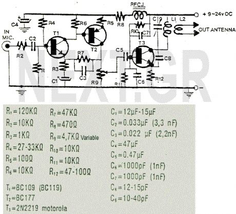
This is a nice 2 Watts FM transmitter. It has a Super-Sensitive pre-amplification with BC109 and BC177 with more than 100% signal modulation. The job finish the 2N2219 by Motorola. For the Coils you should use 1mm wire(enameled), L1= 3 turns - 10mm diameter, L2= 1 turn - 10mm diameter. R9 trimmer controls the modulation gain. The tunning is easy by controlling C9 trimmer (88-108 MHz). The RFC J should be the VK220J with ferrite (VK200 is not suitable).
Source: NEXT.GR (View)
View full Circuit Diagram | Comments | Reading(3117)
FM surveillance BuG Transmitter
Published:2012/9/13 20:50:00 Author:Ecco | Keyword: FM surveillance BuG , Transmitter
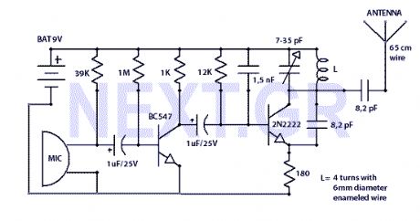
The Circuit shown can transmit voice to exceptionally good range. Tune trimmer to hear the signal to your near radio. Frequency range is 88-108 MHz. Max current consumption is 30mA. You can power the bug with a 9Volt Battery, or you can plug a power supply to feed in 9-12 Volts.
Source: NEXT.GR (View)
View full Circuit Diagram | Comments | Reading(2826)
Simple Infra-Red Transmitter/reciever Shematics
Published:2012/9/13 3:53:00 Author:Ecco | Keyword: Simple , Infra-Red Transmitter, reciever

This 1 channel infrared transmitter/receiver remote control is the cheapest and simplest you can find. The transmitter transmits a sequence of pulses on 36 KHz frequency carrier. The diodes are Schottky type because of their low voltage drop (only 0.2V). The ripple counter 74HC4060 contains an oscillator which controls the frequency carrier to be 36KHz.
Source: NEXT.GR (View)
View full Circuit Diagram | Comments | Reading(2346)
Quality FM-TV micro transmitter 40-200 Mhz
Published:2012/9/12 20:52:00 Author:Ecco | Keyword: Quality, FM-TV, micro transmitter, 40-200 Mhz
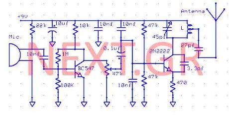
This Transmitter can be powered by a battery 9V (not more than 12V). You can connect your music source where the microphone is or use a simple condenser microphone. The range of signal can reach 400 meters in open air. The wide range of frequency is up to you. Tune it at FM band (88-108) or TV band 40-80Mhz. Play with the Coil and the variable capacitor to tune it to any frequency you want as long as you got the receiver. (View)
View full Circuit Diagram | Comments | Reading(2808)
HiFi expandor with De-emphasis
Published:2012/9/10 21:04:00 Author:Ecco | Keyword: HiFi expandor , De-emphasis
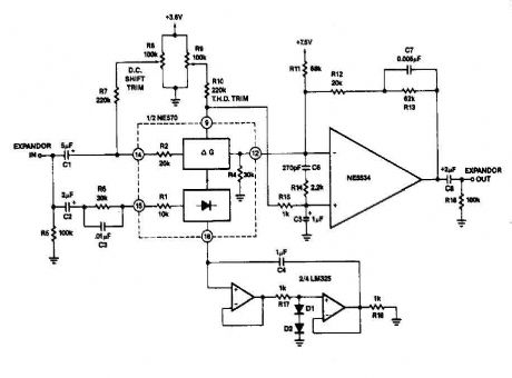
it can reduce its gain. The time it takes for the compressor to recover from overload is determined by the rectifier The expander eg capacitor to complete the compressor is shown in FIG. 2-13B. Here is an external op amp is used for the high rate of ascent. The compressor and expander have unity gain at 0 dB. Trim networks are shown for distortion (THD) and DC offset.
Source: discovercircuits (View)
View full Circuit Diagram | Comments | Reading(1)
FSK Demodulator/Tone Decoder with RC2211N
Published:2012/9/10 20:58:00 Author:Ecco | Keyword: FSK Demodulator, Tone Decoder
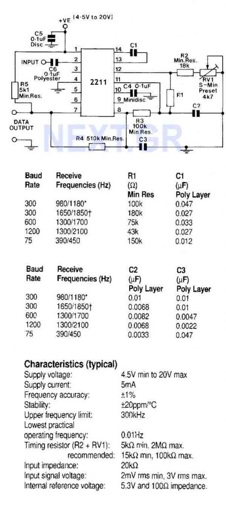
A monolithic phase locked loop for data communications. The IC contains a basic phase locked loop for tracking an input signal within the pass band, a quadrature phase detector which provided carrier detector and an FSK voltage comparator which provides FSK demodulation. In the circuit shown, the IC is used as an FSK demodulator such as would be found in the receiver circuit of a modem.
Source: discovercircuits (View)
View full Circuit Diagram | Comments | Reading(2929)
DK04 Monitoring Module and Computer communication interface circuit
Published:2011/8/22 21:09:00 Author:muriel | Keyword: Monitoring Module, Computer communication interface circuit
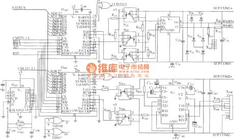
As shown in figure, D187 is an UART, it'sRX / TX signalconnectedonoptocoupler N21, N22 and N29, so that put the RS-485communication interface receiver / transmitter D28and microprocessor D211 completely optoelectronicisolated. D197 is a generator, the currently communication rate is 9600bit / s. D189 is another universal asynchronous receiver transmitter. Optocouplers N204 and N206 areisolated the local RS-232 communication port and the microprocessor D211 completely. D209 canmake a single 5V voltage transform into ± l2V communications special RS-232 drive chip.
(View)
View full Circuit Diagram | Comments | Reading(2226)
| Pages:4/32 1234567891011121314151617181920Under 20 |
Circuit Categories
power supply circuit
Amplifier Circuit
Basic Circuit
LED and Light Circuit
Sensor Circuit
Signal Processing
Electrical Equipment Circuit
Control Circuit
Remote Control Circuit
A/D-D/A Converter Circuit
Audio Circuit
Measuring and Test Circuit
Communication Circuit
Computer-Related Circuit
555 Circuit
Automotive Circuit
Repairing Circuit