
Communication Circuit
Index 17
LIGHT_BEAM_VOICE_TRANSMITTER
Published:2009/7/6 6:02:00 Author:May
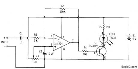
Opamp and transistor together provide amplitude modulation of LED in accordance with amplitude variations of microphone output signal. Requires only single 9-V supply. Other three sections of opamp are not used. Designed for dynamic microphone. Q1 is 2N2222 (Radio Shack 276-2009).-F. M. Mims, Optoelectronic Projects, Vol. 1, Radio Shack, Fort Worth, TX, 1977, 2nd Ed., p 34-43. (View)
View full Circuit Diagram | Comments | Reading(2113)
50_Mb_s_FIBER_OPTIC_RECEIVER
Published:2009/7/6 5:04:00 Author:May
The optical signal is coupled to the pin diode. Current flowing in the diode also flows into the input of the NE5211 preamplifier. The preamplifter is a fixed-gain block that has a 28-KΩ differential transimpedance and does a single-ended to differential conversion. With the signal in differential form, greater noise immunity is assured. The second stage, or postamplifter NE5214, includes a gain block, auto-zero detection, and limiting. The auto-zero circuit allows dc coupling of the preamplifier and the postamplifter and cancels the signal dependent offset because of the optical-to-electrical conversion. The auto-zero capacitor must be 1000 pF or greater for proper operation. The peak detector has an external threshold adjust-ment, RTH, allowing the system designer to tailor the threshold to the individual's need. Hysteresis included to minimize jitter introduced by the peak detector, and an extemal resistor, RHYS, is used to set the amount of hysteresis desired. The output stage provides a single-ended TTL data signal with matched rise and fall times to minimize duty-cycle distortion. (View)
View full Circuit Diagram | Comments | Reading(1249)
DIGITAL_FIBER_OPTIC_RECEIVER
Published:2009/7/6 4:54:00 Author:May
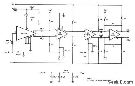
This receiver uses the NE5212, the Signetics 10116 ECL line receiver, and the Phillips/Amperex BPF31 pin diode. The circuit is a capacitor-coupled receiver and utilizes positive feedback in the last stage to provide the hysteresis. The amount of hysteresis can be tailored to the individual application by changing the values of the feedback resistors to maintain the desired balance between noise immunity and sensitivity. At room temperature, the circuit operates at 50-M baud with a BER of 10E-10 and over the automotive temperature range at 40-M baud with a BER of 10E-9. Higher speed experimental diodes have been used to operate this circuit at 220-M baud with a BER of 10E-10. (View)
View full Circuit Diagram | Comments | Reading(1538)
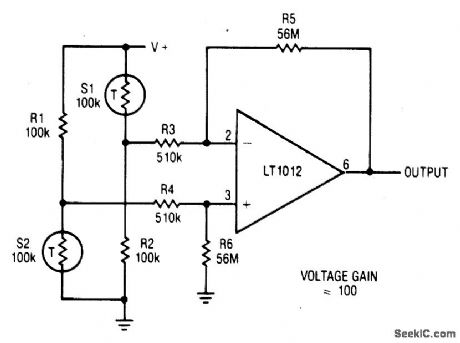
AMPLIFIER_FOR_BRIDGE_TRANSDUCERS
Published:2009/7/6 4:47:00 Author:May
View full Circuit Diagram | Comments | Reading(914)
LOW_COST_100_M_BAUD_FIBER_OPTIC_RECEIVER
Published:2009/7/6 4:46:00 Author:May
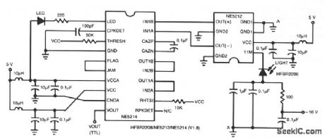
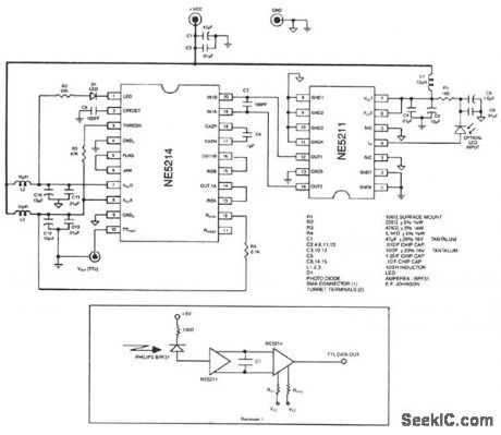
This two-chip receiver with minimum external component count has been designed for low-cost fiber optic applications to 100-M baud (50 MHz). The receiver is divided into pre- and postamplifier ICs for increased stability. The preamplifier IC features low noise with a differential transresistance design. The postamplifier IC incorporates an auto-zeroed first stage with noise shaping, high-gain symmetrical-limiting amplifier, and a matched rise/fall time TTL output buffer. A wide-band full-wave rectifier functions as a link-status indicator. To ensure stability, a surface mount, small outline (SO), package is used. The received signal in the - 35 dBm optical (average) to -9 dBm range is converted into a small unipolar current by the pin diode. The pin diode then feeds its signal current to a preamplifier, such as the NE5212.The preamplifier output is fed to a high-gain limiting amplifier, simply known as the post amp.
The NE5214/NE5217 postamplifters are low-cost ICs that provide up to 60 dB of gain at 50 MHz to bring mV level signals up to TTL levels. The postamplifter IC incorporates an auto-zeroed first stage with noise shaping, a high-gain symmetrical-limiting amplifier, and a matched rise/fall time TTL output buffer. A secondary amplifier chain functions as a link-status indicator. (View)
View full Circuit Diagram | Comments | Reading(1135)
FIBER_OPTIC_TRANSMITTER
Published:2009/7/6 4:30:00 Author:May
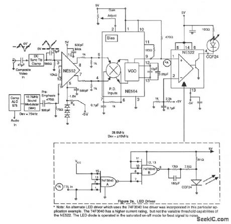
This receiver circuit consists of wideband differential amplifier NE592, VCO NE564 and LED driver NE522-the high-speed comparator. The video signal is ac coupled into the modulator preamplifier and followed by a sync tip clamp to provide dc restoration on the composite video signal and to prevent variation of modulation deviation with varying picture content. A video signal level of 250 to 300 mV peak is required to maintain optimum picture modulation. Frequency compensation (preemphasis) is inserted in the form of a passive rc lead network at the input to the NE592 differential amplifier. The main FM modulator consists of an NE564 used only as a linear wideband VCO, but the other sections of the device are not used. Differential dc coupling to the VCO terminals is attained via the loop filter terminals, pins 4 and 5. (View)
View full Circuit Diagram | Comments | Reading(3969)
PRECISION_THRESHOLD_DETECTOR
Published:2009/7/6 2:19:00 Author:May
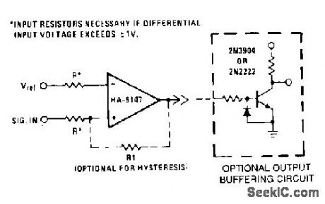
This circuit requires low noise, low and stable offset voltages, high open loop gain, and high speed. These requirements are met by the HA-5147. The standard variations of this circuit can easily be implemented using the HA-5147. For example, hysteresis can be generated by adding R1 to provide small amounts of positive feedback. The circuit becomes a pulse width modulator if Vref and the input signal are left to vary. Although the output drive capability of this device is excellent, the optional buffering circuit can be used to drive heavier loads, preventing loading effects on the amplifier. (View)
View full Circuit Diagram | Comments | Reading(1180)
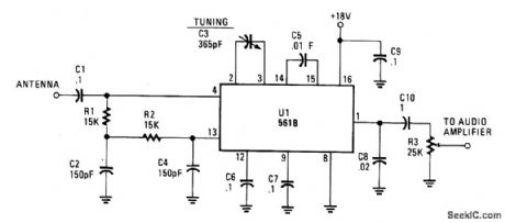
PLL_BC_RECEIVER
Published:2009/7/6 2:18:00 Author:May
Circuit Notes
This simple AM circuit uses a 561B. There's no inductance/capacitance tuning circuit.The 365 pF capacitor connected between pins 2 and 3 does a11 the tuning. The circuit needs a good outside antenna and a solid ground. And if you want to further improve operation, stick a broadband amplifier in front of the receiver. Just make sure the input voltage does not climb over 0.5 volt rms. (View)
View full Circuit Diagram | Comments | Reading(1430)
TRANSMITTER_FOR_REMOTE_TERMINAL
Published:2009/7/5 22:45:00 Author:May
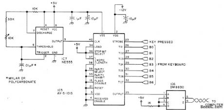
Consists of AY-5-1013 UART attached to keyboard, with twisted-pair cable running to receiver unit at computer location. Coaxial extension cable for monitor is only other connection to computer system because terminal has own power supply. Transmission is in one direction only. NE555 oscillator is set at 1760 Hz ± 1% with aid of frequency counter, for 110-b/s serial rate. IC6 is 5-V National DM8830 differential line driver or equivalent. Pin 14 of IC6 goes to +5 V and pin 7 to ground.-S. Ciarcia, Come Upstairs and Be Respectable, BYTE, May 1977, p 50-54. (View)
View full Circuit Diagram | Comments | Reading(1633)
50_kHz_CENTER_FREQUENCY_FM_OPTICAL_TRANSMITTER
Published:2009/7/5 22:38:00 Author:May
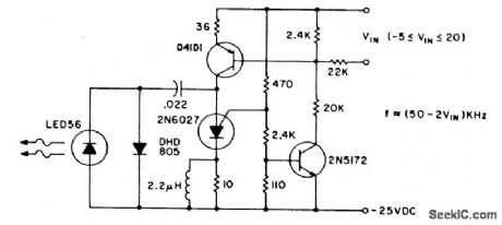
The pulse repetition rate is relatively insensitive to temperature, and power supply voltage and is a linear function of VIN, the modulating voltage. Useful information transfer was obtained in free air ranges of 12 feet (≈4m). Lenses or reflectors at the light emitter and detector increases range and minimizes stray light noise effects. Greater range can also be obtained by using a higher power output IRED such as the F5D1 in combination with the L14P2 phototransistor. Average power consumption of the transmitter circuit is less than 3 watts. (View)
View full Circuit Diagram | Comments | Reading(1073)
Remote control coding transmitting and decoding receiving circuit composed of the M303S/303R
Published:2011/8/1 1:45:00 Author:Christina | Keyword: Remote control, coding, transmitting, decoding, receiving
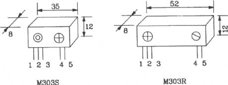
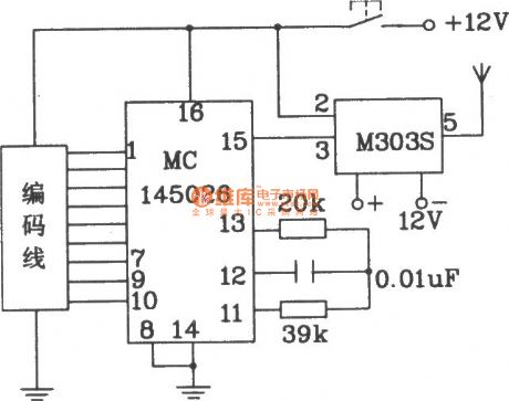

The M303S/303R is designed as one kind of minitype remote control coding transmitting and decoding receiving circuit. It can be used in the short distance data transmission application, because the module uses the dedicated frequency stabilization unit circuit, so the performance of it is stable. This module can be used in the remote control switches, anti-theft alarm devices and the small toys.
The M303S transmitter module is the controllable oscillator & power amplifier unit. The antenna configuration and tuning decides the best operating state of the module, and both of the configuration and tuning directly affect the output power and transmission distance.
(View)
View full Circuit Diagram | Comments | Reading(1318)
Wireless remote control transmitting and receiving circuit composed of the RX5019/5020
Published:2011/8/1 1:56:00 Author:Christina | Keyword: Wireless, remote control, transmitting, receiving
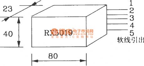
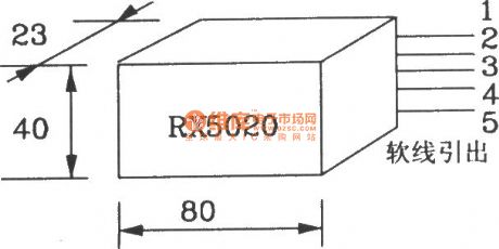

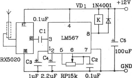
The RX5019/5020 is designed as one kind of wireless remote control transmitting and receiving circuit. The operating frequency of it is stable and not easy to change, the circuit is simple and east to use, you can use it by connecting the outgoing line with the power and signal. They can be used alone or together, it is the perfect wireless remote control launch/receiving device.
The transmitting distance of it can be 3-5km in the unobstructed environment, and the transmitting distance can be 1-3km in the city. If the occasion is fixed, you can use a coaxial cable to connect it with the rod antenna, so the air signal transmission distance can be 8km. The the signal input of the emission component RX5019 can be the voice signals or the audio oscillator signals, the music IC signals and the microphone signals.
(View)
View full Circuit Diagram | Comments | Reading(2044)
BX-1387/BX-1407 (TV, video tape recorder, audio equipment and air conditioner) infrared remote control receiving circuit
Published:2011/8/1 8:26:00 Author:Christina | Keyword: TV, video tape recorder, audio equipment, air conditioner, infrared, remote control, receiving circuit
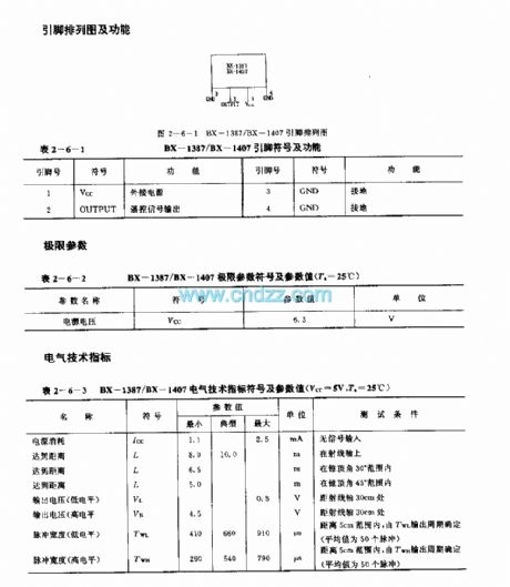
The BX-1387/BX-1407 is designed as the infrared remote control receiving circuit that can be used in the TV, video tape recorder, audio equipment and air conditioner applications. The carrier frequency of the BX-1387 is 40kHz, the carrier frequency of the BX-1407 is 38kHz.
Features
It uses the lastest hybrid circuit technology, so there is no need of the external components.It uses the square pot-type package, the internal circuit has the needle-like optical diode and the preamplifier integrated circuit CX20106A.The high reliability, small size, low voltage and low power consumption.The power voltage range is 4.7-5.3V.It is in the 4-pin square pot-type package.
(View)
View full Circuit Diagram | Comments | Reading(3138)
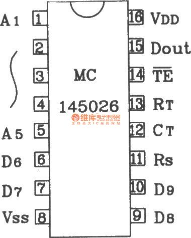
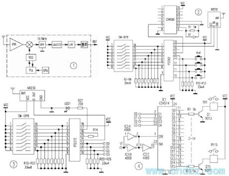
Distant range remote control coding and decoding transmitting and receiving component circuits
Published:2011/7/26 2:28:00 Author:Christina | Keyword: Distant range, remote control, coding, decoding, transmitting, receiving
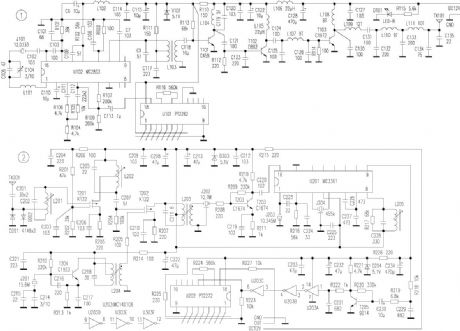
The transmitter components circuit principle
The main technical parameters of the transmitter components are: frequency modulation system; the operating frequency is 36.1MHz; the power voltage is 12V, the transmitter current is less than or equal to 1.5A.
The transmitter components are composed of the coding signal generator circuit, modulated signal amplifier circuit, the transmitter LO circuit, the 3 times frequency amplifier circuit, the high frequency amplifier circuit, the high frequency power amplifier circuit, the coded signal generating circuit uses the special coding circuit U101(PT2262), the modulated signal amplifier circuit, the transmitter local oscillator circuit and the pulse (square wave) modulation circuit use the U102(MC2833). The modulated high-frequency signal is output by the pin of U102.
(View)
View full Circuit Diagram | Comments | Reading(2081)
HANDSHAKING
Published:2009/7/5 21:59:00 Author:May
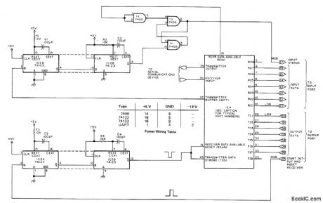
Circuit sets up operating connection between computer and UART (universal asynchronous receiver-transmitter). Eighth bits of I/O ports indicate when data has been successfully transmitted and system is ready to transmit more information. Can be adapted to ny 8-bit computer. IC4 is standard UART such as Signetics 2536, General lnstruments AY 5 1012, Texas Instruments TMS 6011, or American Microsystems S1883. Receiver of UART has seven data lines connected to input port. Article covers handshaking operation in detail and gives typical software routines for parallel I/O handshaking. Technique permits running UART at any desired clock speed, as long as all clocks in system are matched.-T. McGahee, Save Software: Use a UART for Serial IO, BYTE, Dec.1977, p 164-166. (View)
View full Circuit Diagram | Comments | Reading(2620)
8OO_Hz_SINGLE_TRANSlSTOR
Published:2009/7/5 21:58:00 Author:May
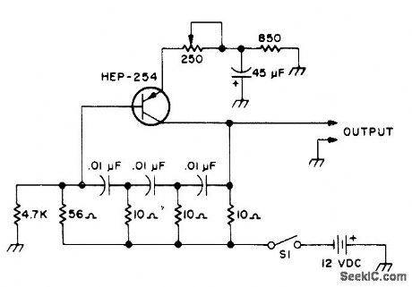
Ladder network determines frequency. For higher frequencies, decrease values of capaeitors in network.Circuit also works with OC-2. SK-3004. and AT30H transistors.-Circuits. 73 Magazine. May 1977. p 31. (View)
View full Circuit Diagram | Comments | Reading(1083)
Phase locked loop secondary frequency conversion wireless transceiver circuit corresponds the industrial remote control GB
Published:2011/7/25 21:48:00 Author:Christina | Keyword: Phase, locked loop, secondary frequency, conversion, wireless, transceiver circuit, industrial, remote control, GB
The NT230 launch module uses the special import high stability crystal (it is not the surface acoustic wave resonator). It outputs the stable 230MHz radio frequency FSK signal, and the emission current is very small, when the power is 5V/8mA, the output voltage is 110dBuV (75Ω load).
The NR230 receiving module diagram is as shown in figure 1, the modulated coded signal which is from the antenna is amplified and mixed by the circuit, then it is sent into the second mixer which is composed of the LA3372, after the original signal is detected out, it gets through the low-pass circuit and the amplification shaping circuit.
(View)
View full Circuit Diagram | Comments | Reading(1556)
BX-1393/BX-1408 (TV, video, audio equipment and air conditioner) infrared remote control receiving circuit
Published:2011/8/1 2:55:00 Author:Christina | Keyword: TV, video, audio equipment, air conditioner, infrared, remote control, receiving circuit
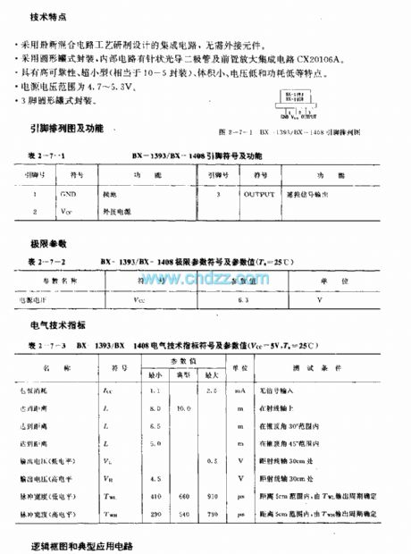
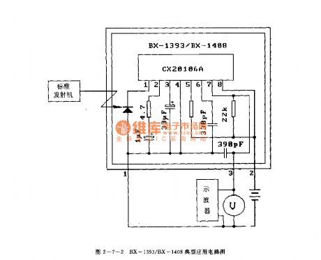
The DX-1393/BX-1408 is designed as one kind of infrared remote control receiving circuit that can be used in the TV, video, audio equipment and air conditioner applications. The carrier frequency of the BX-1393 is 40kHz, the carrier frequency of the BX-1408 is 38kHz.
Features
It uses the latest hybrid circuit technology, so there is no need to use the external components.It uses the circular tank package, the internal circuit has the needle-like optical diode and the preamplifier IC CX20106A.It has the high reliability, ultra-small package, small size, low voltage and low power consumption.The power supply volateg is 4.7-5.3V.The 3-pin circular tank package.
(View)
View full Circuit Diagram | Comments | Reading(3574)
Livestock guardrail disconnection alarm wireless FM receiver circuit
Published:2011/8/1 2:37:00 Author:Christina | Keyword: Livestock, guardrail, disconnection, alarm, wireless, FM, receiver
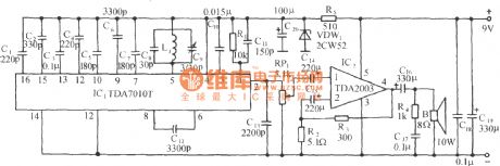
This receiver can be used with the livestock guardrail disconnection alarm wireless transmitter circuit, you can install it in the duty room or carry by the monitor staff, if the guardrail is disconnected, it will receive the FM signal (88 ~ 108MHz), the receiver speaker will send out the sound of animals. The circuit is as shown in the figure. The FM receiver uses one piece of FM ASIC TDA7010T as the core. The receiving range is 88~108MHz, and the receiving range is corresponding with the transmitting frequency. The parallel resonant circuit is composed of the L1, C8 and C9, and it can be used to adjust or track the transmitting frequency.
(View)
View full Circuit Diagram | Comments | Reading(1969)
TRIAC_GAS_SMOKE_DETECTOR
Published:2009/7/3 5:16:00 Author:May
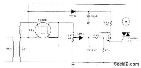
Conductivity of Taguchi TGS308 gas sensor increases in presence of combustible gases, increasing load voltage across R1 from normal 3 VRMS to as much as 20 V. Rise in voltage trips comparator to turn on transistor Q1 that supplies trigger current to 2N6070A sensitivegate triac. Resulting fullwave drive of Delta 1600316824-VAC horn gives sound output of 90 dB at 10 feet. Horn stops automatically when gas clears sensor.-A.Pshaenich, Solid State Gas/Smoke Detector Systems, Motorola, Phoenix, AZ, 1975, AN-735,p4. (View)
View full Circuit Diagram | Comments | Reading(1199)
| Pages:17/32 1234567891011121314151617181920Under 20 |
Circuit Categories
power supply circuit
Amplifier Circuit
Basic Circuit
LED and Light Circuit
Sensor Circuit
Signal Processing
Electrical Equipment Circuit
Control Circuit
Remote Control Circuit
A/D-D/A Converter Circuit
Audio Circuit
Measuring and Test Circuit
Communication Circuit
Computer-Related Circuit
555 Circuit
Automotive Circuit
Repairing Circuit