
Control Circuit
Index 138
Solid_state_relay
Published:2009/7/22 3:15:00 Author:Jessie
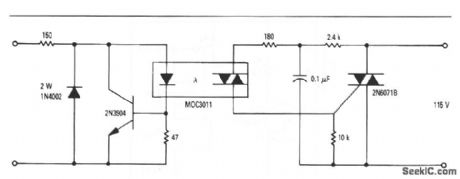
This circuit shows a complete, general-purpose, solid-state relay, snubbed for 115-V inductive 5-V loads. The 5-V input is protected by the MOC3011 optoisolator. The output is snubbed by the 2.4-kΩ resistor and 0.1-μF capacitor. (View)
View full Circuit Diagram | Comments | Reading(0)
Battery_powered_12_volt_5_MHz_frequency_counter_using_McMOS_logic
Published:2009/7/22 5:43:00 Author:Jessie
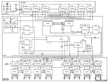
Battery powered (12-volt) 5 MHz frequency counter using McMOS logic (cour tesy Motorola Semiconductor Products Inc.).
(View)
View full Circuit Diagram | Comments | Reading(845)
9_digit_multifunction_counter_using_the_Intersil_ICM7226A_40_pin_DIP
Published:2009/7/22 5:36:00 Author:Jessie
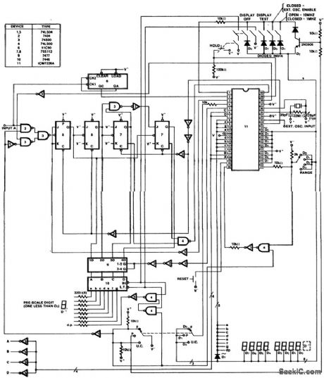
9-digit multifunction counter using the Intersil ICM7226A 40-pin DIP (courtesy Intersil, Inc.). (View)
View full Circuit Diagram | Comments | Reading(921)
emperature_controller_that_uses_zero_point_switching
Published:2009/7/22 4:21:00 Author:Jessie
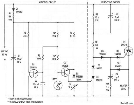
This circuit shows the basic UJT building block (Fig. 9-1), which is used to control a zero-point switching temperature controller. The circuit applies the correct amount of power on a continuous basis at a steady-state duty cycle, depending on the load requirements. Temperature is therefore controlled over a very narrow range and no EMI is generated, The temperature is set by R7. (View)
View full Circuit Diagram | Comments | Reading(806)
Time_delay_with_constant_charging_current
Published:2009/7/22 3:51:00 Author:Jessie
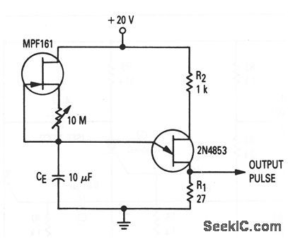
This circuit shows the basic UJT building block (Fig. 9-1), which is used to provide a time-delay function, where the charging current is constant and relatively small (less than 1 μA). This is done by replacing the basic RE, with a JFET and 10-MΩ pot. The 1-μA constant-charging current provides time delays up to about 10 min. (View)
View full Circuit Diagram | Comments | Reading(800)
Optocoupler_that_is_used_as_a_pulse_stretcher
Published:2009/7/22 22:03:00 Author:Jessie
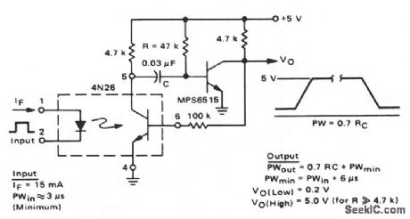
This circuit shows a 4N26 combined with a standard one-shot to form a pulse stretcher. A pulse of about 3 μs at 15 mA triggers the circuit. The output pulse amplitude is a function of supply voltage on the output side, and is independent of the input. (View)
View full Circuit Diagram | Comments | Reading(757)
AC_STATIC_SPDT_SWITCH
Published:2009/7/6 20:11:00 Author:May
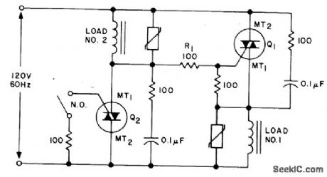
An SPDT solid state relay is shown. When voltage is applied Q1 will tum on, activating load #1, because the full line voltage appears across Q2, supplying gate current through R1. When S1 is closed, Q2 turns on removing the gate drive from Q1 and activating load #2. (View)
View full Circuit Diagram | Comments | Reading(970)
SOLID_STATE_STEPPING_SWITCN
Published:2009/7/6 20:10:00 Author:May
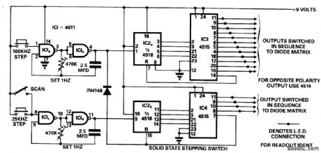
This circuit was designed to make switching of a 48-channel mobile transceiver safe to operate while mobile. The oscillators allow for single-stepping or a scanning function.The scan facility allows for stepping through all 48 channels to check for occupancy or otherwise, and each output is indicated with an LED and labeled accordingly, so at-aglance indication is possible. With full scope of this circuit it is possible to scan 256 channels and by adding more 4 to 16 line encoders etc. you could switch to any required number. (View)
View full Circuit Diagram | Comments | Reading(1688)
Phase_control_circuit_that_uses_a_PUT
Published:2009/7/22 4:11:00 Author:Jessie
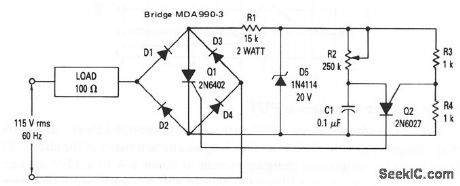
This circuit shows a PUT that is used to control phase of an SCR. The relaxation oscillator that is formed by Q2 provides conduction control of Q1 from 1 to 7.8 ms (21.6° to 168.5°). This constitutes control of over 97% of the power that is available to the load. Only one SCR is needed to provide phase control of both the positive and negative portion of the sine wave, by putting the SCR across the bridge, which is composed of diodes D1 through D4. (View)
View full Circuit Diagram | Comments | Reading(792)
Long_duration_timer_that_uses_a_PUT
Published:2009/7/22 4:08:00 Author:Jessie
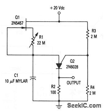
This circuit shows a PUT that is used as a long-duration (up to about 20 minutes) timer. The circuit is similar to that of Fig. 9-20. However, the PUT is superior to the UJT in long-duration timers because the PUT has a lower peak-point firing current (making it possible to charge the capacitor over a longer time). (View)
View full Circuit Diagram | Comments | Reading(768)
WATER_LEVEL_SENSOR_AND_CONTROL
Published:2009/7/6 9:20:00 Author:May

When the water level is low, the probe is out of the water and SCR1 is triggered on. It conducts and imposes a heavy load on transformer T1's secondary winding. That load is reflected back into the primary, gating triac TR1 on, which energizes the load. If the load is an electric valve in the water-supply line, it will open and remain open until the water rises and touches the probe; this shorts SCR1's gate and cathode, thereby turning off the SCR1, which effectively open-circuits the secondary. That open-circuit condition, when reflected back to the primary winding, removes the triac's trigger signal, thereby turning the water off. (View)
View full Circuit Diagram | Comments | Reading(999)
FLOOD_ALARM_OR_TEMPERATURE_MONITOR
Published:2009/7/6 9:17:00 Author:May
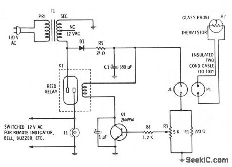
Filtered 15 Vdc is applied to a series circuit consisting of thermistor R2 and parallel combination of resistors R1 and R3. Transistor Q1 acts as a switch whose state is determined by the setting of potentiometer R3, which is first set so just enough current flows into the base to switch on when the thermistor is in contact with air. When the resistance of the thermistor decreases, the voltage at the base of Q1 rises. When the base current reaches the preset level, the transistor conducts and passes current through the reed relay coil, closing the reed relay contacts. Current at the base of transistor Q1 is determined by the environment into which the termistor is inserted. (View)
View full Circuit Diagram | Comments | Reading(769)
Long_duration_time_delay
Published:2009/7/22 3:56:00 Author:Jessie
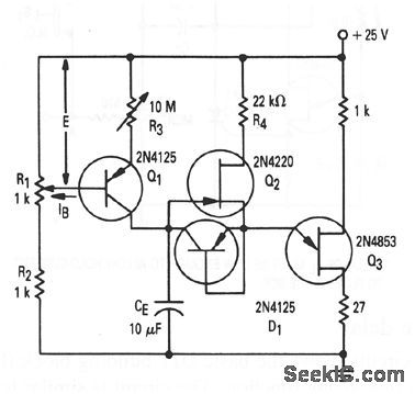
This circuit shows the basic UJT building block (Fig. 9-1), which is used to provide long time delays (up to 10 hours). Q1, R1, R2, and R3 form a constant-current source to charge CE very slowly (a few nA) to provide the long delay. Q2 and D1 (a 2N4125 connected as a diode) provide a separate discharge path to the emitter of UJT Q3. Notice that there is some interaction between R1 and R3 when setting the time delay. (View)
View full Circuit Diagram | Comments | Reading(0)
FLUID_LEVEL_CONTROL
Published:2009/7/6 9:14:00 Author:May
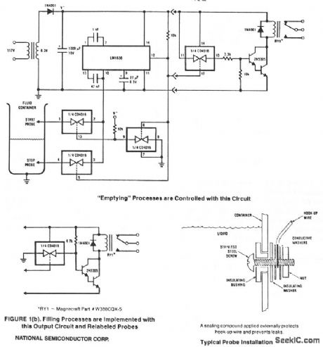
This circuitis designed to detect the presence or absence of aqueous fluids. An ac signal generatedon-chipis passed through two probes within the fluid. A detector determines the presence of the fluid byusmg the probes in a voltage divider circuit and measunng the signal level across the probes. An ac signalis used to prevent plating or dissolving of the probes as Occurs when a dc signal is used. A pinis availablefor connecting an external resistancein cases where the fluid impedanceis not compatible with the internal 13-KΩ divider resistance. (View)
View full Circuit Diagram | Comments | Reading(787)
9_digit_universal_counter_using_the_ICM7226A_40_pin_DIP
Published:2009/7/22 5:29:00 Author:Jessie
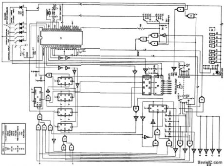
9-digit universal counter using the ICM7226A 40-pin DIP (courtesy Intersil, Inc.). (View)
View full Circuit Diagram | Comments | Reading(1534)
VARIABLE_DE[AY_PULSE
Published:2009/7/22 20:38:00 Author:Jessie
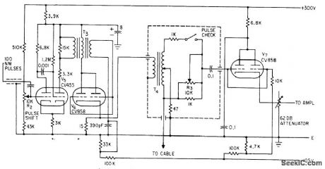
Grid voltage of monostable multivibrator V5 is adjusted by R2 to give delay range of between 171 and 228 microsec, corresponding to 9 to 12 nautical miles of cable under test. Used in pulse echo fault finder to generate transmitted pulse in synchronism with marker pulse generator.-F. Jones and J. H. Reyner, Compact New Instrument Finds Undersea Cable Faults, Electronics, 35:37, p 48-50.
(View)
View full Circuit Diagram | Comments | Reading(711)
EDDY_CURRENT_WIRE_FLAW_DETECTOR
Published:2009/7/22 20:36:00 Author:Jessie
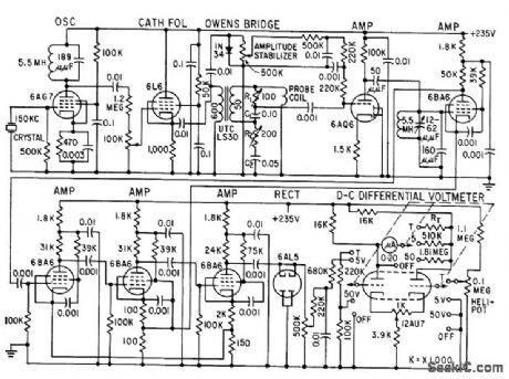
High-sensitivity eddy-current instrument gives me tor indication or permanent record of surface or internal tracts and voids smaller than 0.001 inch in 0.055-inch-diameter zirconium wire used for positioning fuel elements of nuclear reactors. Wire is run through probe coil energized at 150 kc by crystal oscillator, and change in impedance of coil due to law is measured with modified Owens bridge. Output of bridge is amplified in five stages, then rectified for measurement by d-c differential Voltmeter. -R. G. Myers and C. J. Renken, Detecting Invisible Flaws in Wire, Electronics, 31:39, p 72-73. (View)
View full Circuit Diagram | Comments | Reading(1954)
HI_POT_TESTER
Published:2009/7/22 20:24:00 Author:Jessie
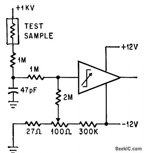
Operational trigger trips when resistance of sample under test is less than 500,000 meg.-P. Lefferts, Operational Trigger For Precise Control, Electronics, 37:28, p 50-55.
(View)
View full Circuit Diagram | Comments | Reading(912)
INDUCTIVE_TELEMETRY_FOR_SPIN_TEST
Published:2009/7/22 20:22:00 Author:Jessie
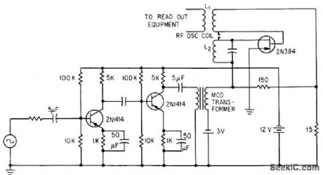
Transistors in modulated oscillator-transducer package withstand over 6,000 rpm on spin test while radiating measured data inductively from oscillator coils L1-L2 to stationary coil of readout equipment.-H. Baumann, Inductive Telemetry Improves Spin-System Measurements, Electronics, 36:46, p 41-42. (View)
View full Circuit Diagram | Comments | Reading(644)
TACHOMETER_TESTER
Published:2009/7/22 20:21:00 Author:Jessie
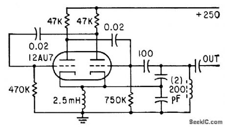
Free-running mvbr, half of which is connected us Colpitts oscillator, gives 1-Mc sine wave, 100% modulated by 15-cps square wave, for testing two-channel tachometer using radioactive sources-R. R. Bockemuehl und P. W. Wood, Unique Two-Channel Tachometer uses Radioisotopes, Electronics, 35:49, p 44-45. (View)
View full Circuit Diagram | Comments | Reading(720)
| Pages:138/312 At 20121122123124125126127128129130131132133134135136137138139140Under 20 |
Circuit Categories
power supply circuit
Amplifier Circuit
Basic Circuit
LED and Light Circuit
Sensor Circuit
Signal Processing
Electrical Equipment Circuit
Control Circuit
Remote Control Circuit
A/D-D/A Converter Circuit
Audio Circuit
Measuring and Test Circuit
Communication Circuit
Computer-Related Circuit
555 Circuit
Automotive Circuit
Repairing Circuit