
Control Circuit
Index 134
Universal_motor_control_with_built_in_self_timer
Published:2009/7/21 23:28:00 Author:Jessie
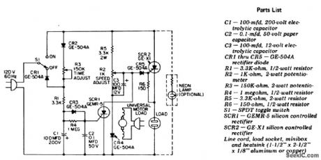
Universal motor control with built-in self-timer. Use this circuit only with motors having commutators. If heavy motor loads are anticipated, use a larger-rated C30B SCR in place of the GE-X1 for SCR2. To increase the time delay increase the capacitance of 01 (courtesy General Electric Company). (View)
View full Circuit Diagram | Comments | Reading(0)
VARIABLE_FREQUENCY_AND_RATE
Published:2009/7/21 23:57:00 Author:Jessie
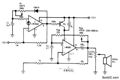
Uses National LM380 opamp as astable oscillator with frequency determined by R2 and C2. Base of Q1 is driven by output of LM3900 opamp connected as second astable oscillator, to turn output of LM380 on and off at rate fixed by R1 and C1. Transistor type is not critical. Circuit is ideal 'tor experimenters.- Audio Handbook, National Semiconductor, Santa Clara, CA, 1977, p 4-21-4-28. (View)
View full Circuit Diagram | Comments | Reading(907)
POLICE_SIREN
Published:2009/7/21 23:56:00 Author:Jessie
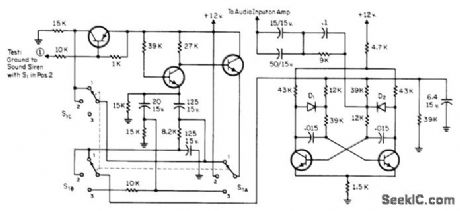
Circuit used in Dietz siren-light police-car system gives distinctive tones. Position t of S1 produces slow continuous rise and fall. Position 3 produces fast rising and falling tone. Position 2 rises slowly to full pitch when point 1 is grounded, then decays at same rate when point 1 is ungrounded. Position 3 gives most noticeable tone for break-in alarm on car. Terminal 1 goes to normally open door, hood, and other switches that complete circuit to ground when opened by intruder. Audio transistors and diode are general replacement types.-J. W. Crawford, The Ultimate Auto Alarm-Model II, CQ, Aug. 1971, p 54-57 and 96. (View)
View full Circuit Diagram | Comments | Reading(252)
Control_of_higher_voltage_motors
Published:2009/7/21 23:48:00 Author:Jessie
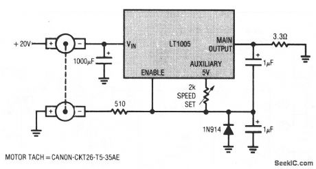
This circuit shows how an LT1005 multifunction regulator can be used to control operation of higher-voltage motors. The circuit is similar to that of Fig. 8-6, except that a 1000-μF capacitor is placed at the regulator to filter transients that are generated by motor switching. When the tach output calls for power, the LTl005 comes on, and allows current to flow through the motor. This forces the LTl005 input toward ground for the duration of the turn-on time. The advantage of this circuit over that of Fig. 8-6 is that higher-voltage motors (up to 20 V) can be used. (View)
View full Circuit Diagram | Comments | Reading(1343)
Time_delayed_relay_for_up_to_1_minute
Published:2009/7/21 23:47:00 Author:Jessie
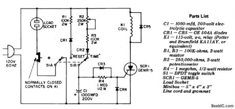
Time-delayed relay for up to 1 minute (courtesy General Electric Company). (View)
View full Circuit Diagram | Comments | Reading(728)
100_MHz_multifunction_counter_using_an_Intersil_ICM7216A_28_pin_DIP
Published:2009/7/21 23:37:00 Author:Jessie

100 MHz multifunction counter using an Intersil ICM7216A 28-pin DIP (courtesy lntersil, Inc.). (View)
View full Circuit Diagram | Comments | Reading(1002)
PPM_WITH_ANALOG_CONTROL_OF_DELAY
Published:2009/7/6 22:37:00 Author:May

Opamp, UJT, and two TTL packages generate pulse whose delay, following sync pulse, is con-trolled by amplitude of analog input signal at time of sync pulse. Opamp precharges timing capacitor to level depending on analog signal. Sync pulse disconnects opamp, after which timing capacitor charges up to UJT firing point .UJT output pulse then resets circuit, giving de-sired delayed output pulse through 9601 mono MVBR,-J. Taylor, Analog Signal Controls Pulse Delay, EDN Magazine, Feb. 5, 1974, p 96. (View)
View full Circuit Diagram | Comments | Reading(1407)
Biochemistry incubator controller circuit
Published:2011/4/14 5:54:00 Author:may | Keyword: Biochemistry, incubator controller
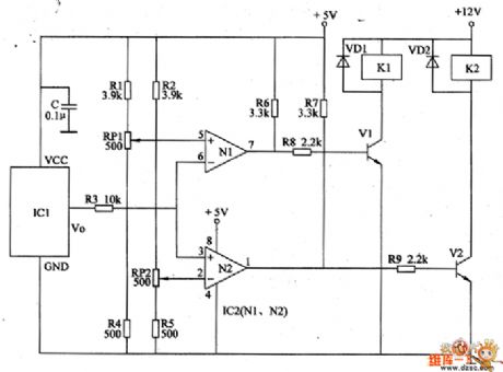
Circuit working principle
This incubator controller circuit consists of temperature sensor, voltage comparator and control and executive circuit. The circuit is shown in the diagram
(View)
View full Circuit Diagram | Comments | Reading(1336)
4_digit_7_function_stopwatch_timer
Published:2009/7/21 23:27:00 Author:Jessie
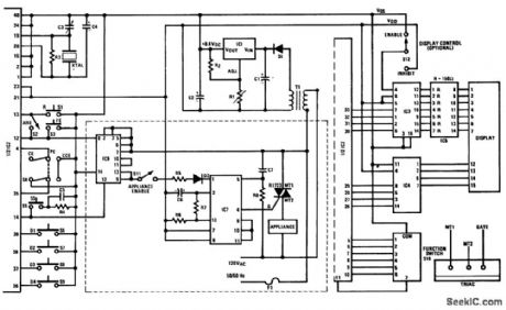

4-digit 7-function stopwatch/timer. See table for switch abbreviations. See parts list for component part numbers and values. This circuit is based on the MM5865 universal timer IC. As drawn the display resolution is 1 second. A SPST switch can be included between pin 16 of IC2 and Vss to provide a resolution of 0.01 second and 1 second. Another option is the display control switch which may be used to inhibit the display (courtesy National Semiconductor Corporation). (View)
View full Circuit Diagram | Comments | Reading(2087)
On_off_temperature_control_with_delayed_turn_on
Published:2009/7/21 23:26:00 Author:Jessie
This circuit uses a CA3059 zero-voltage switch to control operation of atriac. The delay between switch closure and turn-on is set by the values of R1, R2 and C1 as shown by the equations. (View)
View full Circuit Diagram | Comments | Reading(1392)
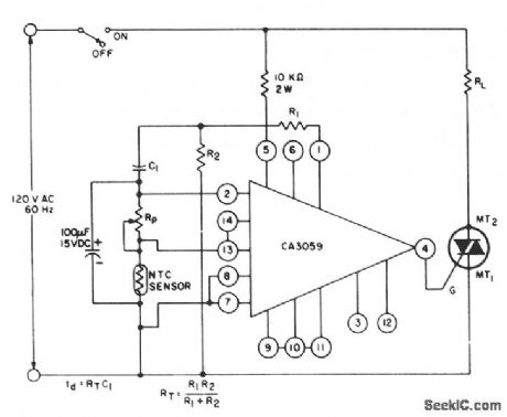
Line_operated_thyristor_control_time_delay
Published:2009/7/21 23:24:00 Author:Jessie
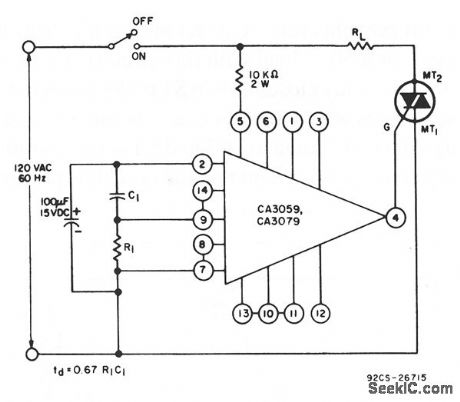
This circuit uses a CA3059 or CA3079 zero-voltage switch to control turn-on time of a triac. The delay between switch closure and turn-on is set by the values of R and C, as shown by the equation. (View)
View full Circuit Diagram | Comments | Reading(1139)
19MHz_universal_counter_using_an_Intersil_ICM7226B_40_pin_DIP
Published:2009/7/21 23:22:00 Author:Jessie
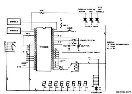
19MHz universal counter using an Intersil ICM7226B 40-pin DIP. This circuit measures frequencies at input A up to 10 MHz and at input B up to 2 MHz (courtesy Intersil, Inc.). (View)
View full Circuit Diagram | Comments | Reading(875)
40_MHz_frequency_counter_using_the_Intersil_ICM7216C_28_pin_DIP
Published:2009/7/21 23:19:00 Author:Jessie
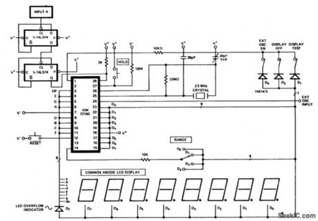
40 MHz frequency counter using the Intersil ICM7216C 28-pin DIP. To measure the correct value the 2.5 MHz oscillator frequency is divided by four as well as the input frequency (courtesy Intersil, Inc.). (View)
View full Circuit Diagram | Comments | Reading(2007)
Relay_contact_protection_that_uses_a_triac
Published:2009/7/21 23:19:00 Author:Jessie
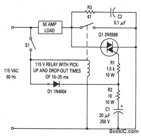
This circuit prevents relay-contact arcing for loads up to 50 A (many 5-A relays can be used for a 50-A load with this circuit). Using the values shown, triac Q1 turns on before the relay closes (when S1 is closed) and remains on after the relay opens. This minimizes arcing (and contact bounce ), even though the load current passes through the relay contacts. R3 and C1 act as a snubber to reduce dv/dt, if any other switching element is used on the line (and thus prevents Q1 from being turned on by transients). (View)
View full Circuit Diagram | Comments | Reading(1419)
SINGLE_FREQUENCY_CONTROL
Published:2009/7/6 21:50:00 Author:May
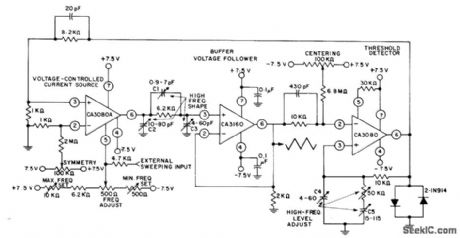
Adjustment range of over 1,ooo,ooo to 1 for frequency is achieved by using CA3080A as programmable current source,CA3160 opamp as voltage follower, and CA3080 variable opamp as high-speed capacitor. Variable capacitors C1-C3 shape triangle waveform between 500 kHz and 1 MHz. C4 and C5 with 50K trimmer in series with C5 maintain constant amplitude within 10% up to1 MHz,-''Circuit Ideas for RCA Linear ICs、″RCA Solid State Division,Somerville,NJ,1977,p 6. (View)
View full Circuit Diagram | Comments | Reading(729)
ADJUSTABLE_SIREN
Published:2009/7/22 1:06:00 Author:Jessie
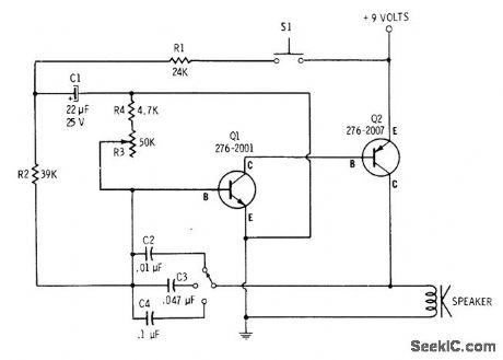
Tone is made adjustable by using multiposition switch to change capacitors in oscillator circuit. Speed (rate of change in frequency) of siren is adjusted with R3. 4700-ohm resistor in series with R3 keeps siren op-erational when R3 is rotated to minimum-resistance position. Siren is operated by pressing switch to produce rising wail, then releasing switch until wail drops down to cutoff.-F. M. Mims, Transistor Projects, Vol.1, Radio Shack, Fort Worth, TX, 1977, 2nd Ed., p 58-63. (View)
View full Circuit Diagram | Comments | Reading(1049)
TWO_TRANSISTOR_MODULATOR_FOR_LIGHT_EMITTING_DIODE
Published:2009/7/22 1:06:00 Author:Jessie

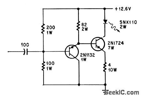
Linear range of 80% modulation for bandwidth of 30 cps to 250 kc, with only 3% distortion at 1 kc, permits good voice transmission over light beams generated by SNX110 Iight-emining diode.-E. L. Bonin, Drivers for Optical Diodes, Electronics, 37:22, p 77-82. (View)
View full Circuit Diagram | Comments | Reading(1267)
HEATER_ELEMENT_TEMPERATURE_CONTROLLER
Published:2009/7/6 21:40:00 Author:May
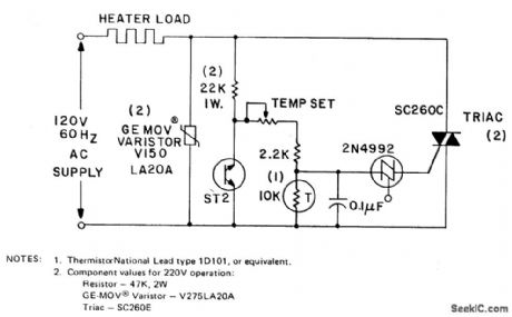
The circuit can control up to 6 kW of heating, with moderate gain,using a 25-amp triac(SC260D). Feedback is provided by the negative temperature co-efficient(NTC)thermistor,which is mounted adjacent to the environment being temperature controlled.The temperature set potentiometer is initially adjusted to the desired heating level.As the thermistor becomes heated by the load ,its resistance drops,phasing back the conduction angle of the triac,so the load voltage is reduced.The ST2 diac is used as a back-to-back ziner diode.Its negativeresistance region in its E-I characteristic Provides a degree of line vdtage stabilization. As the input line voltage increases,the diac triggers earlier in the cycle and, hence, the average charging voltage to the 0.1 μF capacitor,decreases. (View)
View full Circuit Diagram | Comments | Reading(4956)
MAGNETRON_MODULATOR
Published:2009/7/22 1:05:00 Author:Jessie
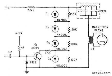
Uses four Shockley diodes in series, triggered by avalanche triode transistor, to give action similar to that of conventional line-type pulser using hydro gen thyratron, but requires no heater power or warmup.-L. Diven, Solid-State Modulator Feeds Subminiature Transponder, Electronics, 33:27, p 48-51. (View)
View full Circuit Diagram | Comments | Reading(1651)
Programmable_ultra_accurate_line_operated_timer_and_load_control
Published:2009/7/22 0:37:00 Author:Jessie
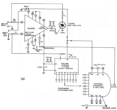
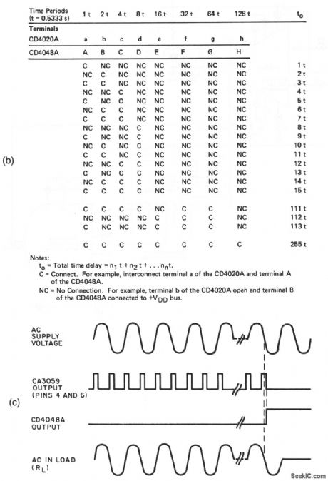
This circuit provides precise current through a load, as determined by a pulsed triac. The circuit is programmable over the range from 0.5333 s to 2 min and 16s, in 0.5333-s intervals. Figure 8-41B shows the connections for the various time intervals, and Fig. 8-41C shows the timing diagram. (View)
View full Circuit Diagram | Comments | Reading(770)
| Pages:134/312 At 20121122123124125126127128129130131132133134135136137138139140Under 20 |
Circuit Categories
power supply circuit
Amplifier Circuit
Basic Circuit
LED and Light Circuit
Sensor Circuit
Signal Processing
Electrical Equipment Circuit
Control Circuit
Remote Control Circuit
A/D-D/A Converter Circuit
Audio Circuit
Measuring and Test Circuit
Communication Circuit
Computer-Related Circuit
555 Circuit
Automotive Circuit
Repairing Circuit