
Control Circuit
Index 139
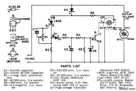
Projection_lamp_voltage_regulator
Published:2009/7/22 21:30:00 Author:Jessie

This circuit is similar to that of Fig. 9-18. Here, the magnitude of the charging current that is applied to capacitor C and the position of R6 sot the firing time of the UJT, which, in turn, sets the firing angle of the SCR. Light from the projection lamp sets the current level in Q3, which diverts current from the timing capacitor. R6 sets the desired brightness level by adjusting the UJT firing time. (View)
View full Circuit Diagram | Comments | Reading(0)
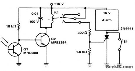
Light_operated_alarm_with_sensitive_gate_SCR
Published:2009/7/22 21:23:00 Author:Jessie
This circuit is similar to that of Fig. 9-41, except that the relay is omitted and a sensitive-gate SCR is used. (View)
View full Circuit Diagram | Comments | Reading(784)
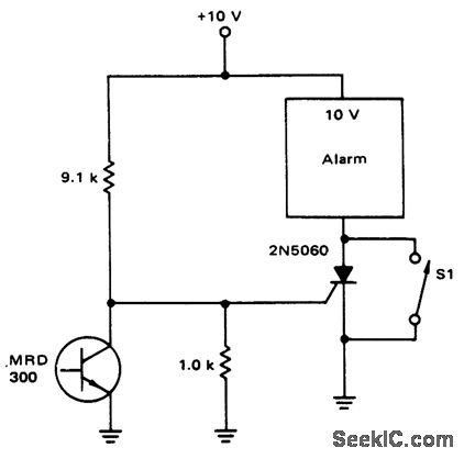
Light_operated_alarm
Published:2009/7/22 21:20:00 Author:Jessie
This circuit shows an MRD300 phototransistor that is used to control an alarm (bell, buzzer, etc.). The alarm is turned on when light is removed from Q1. The alarm remains on (even if the light is restored to Q1 ), until momentary-contact switch S1 is closed. (View)
View full Circuit Diagram | Comments | Reading(843)
Light_deenergized_relay
Published:2009/7/22 21:07:00 Author:Jessie
This circuit shows an MRD300 phototransistor that is used to control a relay, where the relay is deenergized when light is applied to Q1. (View)
View full Circuit Diagram | Comments | Reading(1040)
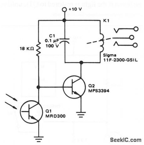
Light_operated_relay
Published:2009/7/22 21:02:00 Author:Jessie

This circuit shows an MRD300 phototransistor that is used to control a relay, where the relay is energized when light is applied to Q1. (View)
View full Circuit Diagram | Comments | Reading(0)
Optoisolator_driver_for_inductive_loads_with_nonsensitive_gate_triacs
Published:2009/7/22 21:00:00 Author:Jessie
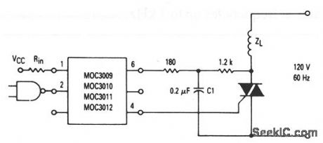
This circuit shows optoisolators (with triac driver outputs) that are used to trigger a nonsensitive-gate triac (IGT greater than 15 mA but less than 50 mA) with inductive load. C1 and the 1.2-kΩ resistor form a snubber for the triac. (View)
View full Circuit Diagram | Comments | Reading(1203)
Optoisolator_driver_for_inductive_loads_with_sensitive_gate_triacs
Published:2009/7/22 20:58:00 Author:Jessie
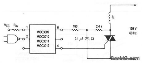
This circuit shows optoisolators (with triac driver outputs) that are used to trigger a sensitive-gate triac (IGT less than 15 mA) with inductive load. C1 and the 2.4-kΩ resistor form a snubber for the triac. (View)
View full Circuit Diagram | Comments | Reading(1622)
ISOLATED_THRESHOLD_SWITCH
Published:2009/7/6 7:43:00 Author:May
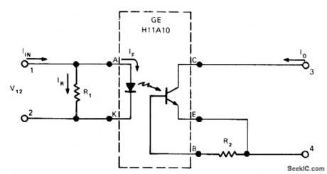
Standard photocoupler programmed with 150-ohm resistor R1 provides threshold switching function for separating high-level noise from switching-signal pulses as short as 10μs. Current-transfer ratio of phototransistor coupler is made practically zero at some arbitrary input current, and changed rapidly back to 10% or more at slightly higher level. Programming range for threshold value extends from 60 mA for 10 ohms at R1 to 3 mA for 400 ohms. Use of 2.7-megohm resistor R2 across base-emitter terminals of coupler reduces low-current gain of phototransistor. Noise currents up to 5 mA on sensing line are rejected while operating currents as low as 10 mA are accepted.-J. Cook, Photocoupler Makes an Isolated Threshold Switch, EDN Magazine, Oct. 5, 1974, p 72, 74, and 76. (View)
View full Circuit Diagram | Comments | Reading(943)
OPTOISOLATOR_INPUT_PROTRCTION
Published:2009/7/6 7:19:00 Author:May

Combination of diode and transistor limits input current to LED of Motorola MOC3011 optoisolator to safe maximum of less than 15 mA for input voltage range of 3-30 VDC. Circuit also protects LED from accidental reversal of polarity.-P.O 'Neil, “Applications of the MOC3011 Triac Driver,” Motorola, Phoenix, AZ, 1978, AN-780, p 4. (View)
View full Circuit Diagram | Comments | Reading(782)
FAST_OPTICALLY_ISOLATED_SWITCH
Published:2009/7/6 7:14:00 Author:May
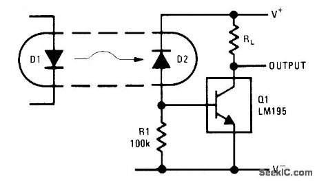
Uses almost any standard optoisolator. Less than 20μA is needed from photodiode D2 to tum LM195 power transistor fully on. Returning cathode of D2 to separate positive supply rather than to collector of al eliminates collector-base capacitance of diode and increases switching speed to 500 ns for 40-V 1-A load.-R. Dobkin, Fast IC Power Transistor with Thermal Protection, National Semiconductor, Santa Clara, CA, 1974, AN-110, p 5. (View)
View full Circuit Diagram | Comments | Reading(922)
TESTING_300_KW_UHF_TUBE
Published:2009/7/22 23:58:00 Author:Jessie
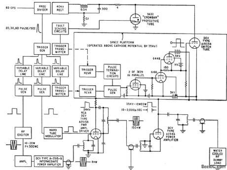
If arc develops in protected A2346 tube, ignitron crowbar circuit grounds power supply in less than 5 microsec. Keying circuits operate at 35-kv plate voltage of tube under lest, applied in pulses 10 to 2,000 microsec wide through switch tube. Peak plate current is almost 300 amp during 5-megcwall output test. -G. Flynn, Super-Power Electron Tube for UHF Band, Electronics, 33:15, p 70-72. (View)
View full Circuit Diagram | Comments | Reading(601)
QUARTZ_OVERIONE_CRYSTAL_CHECKER
Published:2009/7/22 23:50:00 Author:Jessie
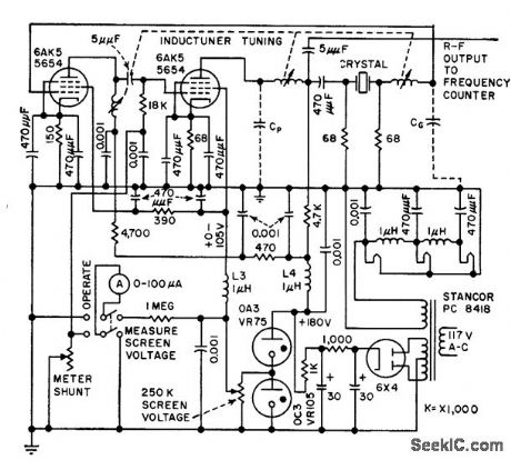
Rapidly measures equivalent parameters, in range of 75 to 200 Mc, by combining active and passive measuring systems. Crystal being measured controls frequency stabiltiy of oscillatory circuit of crystal impedance meter. -D. W. Robertson, Plug-in Bridge Checks VHF Quartz Crystals, Electronics, 3H9, p 82-85. (View)
View full Circuit Diagram | Comments | Reading(924)
Optically_controlled_regulator_shutdown
Published:2009/7/22 22:20:00 Author:Jessie
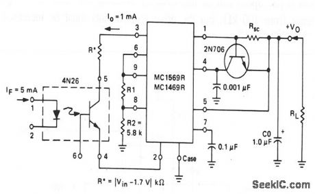
This circuit shows a 4N26 that is used to shut down a voltage regulator. To ensure that the regulator is shut down, input current to the 4N26 LED must be a minimum of 5 mA (to produce 1 mA at thq 4N26 output). (View)
View full Circuit Diagram | Comments | Reading(1673)
RELAY_CONTACT_CHATTER_TESTER
Published:2009/7/22 22:49:00 Author:Jessie

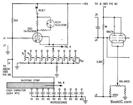
Monitors either open or closed contacts, in 10-microsec increments for intervals of from 10 to 100 microsec. Thyratron conducts if relay contacts remain open (or closed) longer than pre determined interval. Inverter (at right) triggers thyratron during testing of contacts, and is normally open Contacts under test are connected to J3 and J4.-E. H. Kopp, Production Line Checker for Relay Contact Chatter, Electronics, 33:21, p 94-95. (View)
View full Circuit Diagram | Comments | Reading(939)
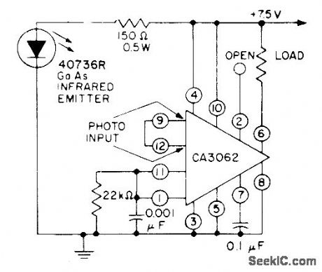
MISSING_PULSE_ALARM
Published:2009/7/6 6:15:00 Author:May
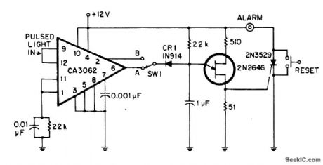
Developed for sensing missing light pulses or detecting absence of object on moving conveyor belt. CA3062 com bination light sensor and amplifier detects light pulses synchronized to 60-Hz line. With SW1 at A, each pulse resets 20-ms timing network of 2N2646 UJT at 16.7-ms intervals, preventing UJT from firing. If light beam is interrupted by object, UJT is allowed to fire and trigger 2N3529 SCR that turns on alarm. With SW1 at B, circuit detects interruptions in steady light beam and sounds alarm only when interruption does not occur.-J. F. Kingsbury, Double Duty Photo Alarm, EDN|EEE Magazine, May 15, 1971, p 51. (View)
View full Circuit Diagram | Comments | Reading(1664)
LIGHT_CHANGE_SENSOR_DRIVES_RELAY
Published:2009/7/6 6:10:00 Author:May

Capacitive coupling between phototransistor and bipolar transistor makes circuit respond only to interruptions or rapid changes in light while ignoring normal gradual changes in ambient light as caused by clouds or at sunrise. Relay pulls in when flash of light occurs and drops out when light is removed, Use Radio Shack 275-004 miniature relay.-F. M. Mims, Transistor Projects, Vol. 3, Radio Shack, Fort Worth, TX, 1975, p 69-74. (View)
View full Circuit Diagram | Comments | Reading(1909)
GARAGE_LIGHT_CONTROL
Published:2009/7/6 6:09:00 Author:May
When mounted on far wall in garage, controller picks up head-light beams as car is driven in at night and turns light. on one or more garage lights long enough (3 min) for driver to get out of car and reach exit. Controller then flickers lights as warning and begins dimming them out. With parts specified, will handle up to 800 W of lamps. Adjust sensitivity control R1 so lighe in optocoupler CPL comes on when headlights strike light-operated SCR. Controller must be kept out of direct sunlight. For manual control, connect, connect pushbutton switch between points A and B. To increase time delay, increase value of C2. With 20μF, time will be doubled.-C. R. Lewart, Automatic Garage Light Control, Popular Science, July 1973, p 110. (View)
View full Circuit Diagram | Comments | Reading(958)
ON_OFF_CONTROL
Published:2009/7/6 6:08:00 Author:May
RCA CA3062 combination photodetector and power amplifier provides ON/OFF output in response to light signal. Out-put transistors in IC should be either saturated or blocked to avoid heat rise in silicon chip. Complementary outputs give choice of load normally on or normally off when light from infrared emitter falls on photo input of IC. Interruption of light path then produces opposite load condition - Linear Integrated Circuits and MOS/FET’s, RCA Solid State Division, Somerville, NJ, 1977, p 156. (View)
View full Circuit Diagram | Comments | Reading(1072)
PHOTOTRANSISTOR_RELAY
Published:2009/7/6 6:07:00 Author:May
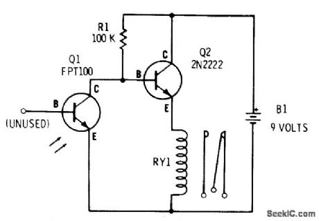
With phototransistor Q1 dark, R1 biases Q2 into conduction and miniature SPDT relay (Radio Shack 275-004) is energized. When light falls on Q1, Q2 is turned off and relay drops out. Battery drain is about 5 mA in darkness, dropping almost to 0 mA with light.-F. M. Mims, Transistor Projects, Vol. 3, Radio Shack, Fort Worth, TX, 1975, p 69-74. (View)
View full Circuit Diagram | Comments | Reading(2881)
LOW_BATTERY_PROTECTOR
Published:2009/7/6 5:58:00 Author:May
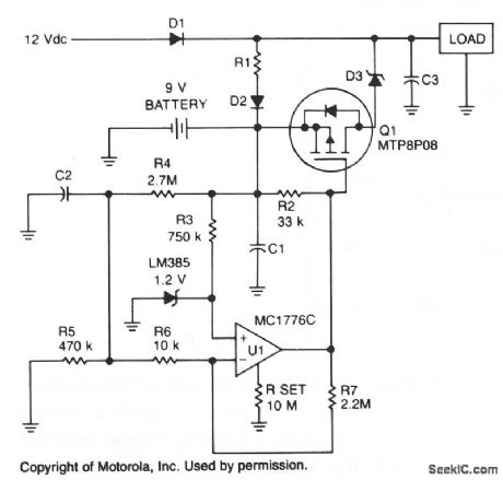
To prevent battery damage due to over-dis-charge, a low-voltage detector and switch should be included in the design of the battery backup circuit.The detector circuit should consume extremely low current. The switch should exhibit a low-voltage drop and be easy to control.
R1 and D2 provide a trickle charge for the battery. Chosen for its low forward voltage drop, Schottky diode D3 prevents forward polarization of the diode incorporated in Q1. When the battery voltage is above approximately 8 V, the output of U1 is low and Q1 is turned on. If the battery voltage falls below 8 V, the output of U1 increases and turns off Q1. (View)
View full Circuit Diagram | Comments | Reading(2409)
| Pages:139/312 At 20121122123124125126127128129130131132133134135136137138139140Under 20 |
Circuit Categories
power supply circuit
Amplifier Circuit
Basic Circuit
LED and Light Circuit
Sensor Circuit
Signal Processing
Electrical Equipment Circuit
Control Circuit
Remote Control Circuit
A/D-D/A Converter Circuit
Audio Circuit
Measuring and Test Circuit
Communication Circuit
Computer-Related Circuit
555 Circuit
Automotive Circuit
Repairing Circuit