
Control Circuit
Index 132
Water_level_control
Published:2009/7/21 22:11:00 Author:Jessie
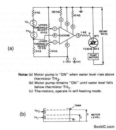
This circuit shows a triac used to provide electronic control of a drain or sump pump. Figure 8-7B shows positioning of the sensor thermistors in the tank that is drained by the pump. The circuit notes explain the operation of the pump Control. (View)
View full Circuit Diagram | Comments | Reading(0)
REMOTE_FREQUENCY_CONTROL
Published:2009/7/7 3:00:00 Author:May
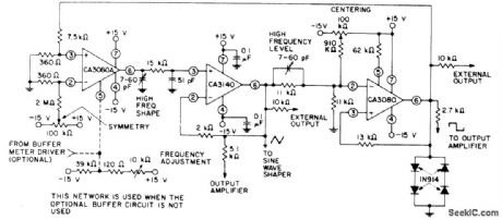
Frequency of square and triangle outputs can be ad justed over range of 1,000,000:1 with 10K pot or by varying DC voltage applied to pin 5 of CA3080A over wire line from remote location. CA3140 serves as noninverting readout amplifier for triangle wave developed across integrating capacitor network at output of CA3080A current source. Second CA3080 acts as high-hysteresis switch having trip level established by four diodes,to give desired square-wave output.-''Linear Integrated Circuits and MOS/FET's,''RCA Solid State Divsion,Somerville,NJ,1977,p 248-254. (View)
View full Circuit Diagram | Comments | Reading(731)
REVOLUTION_COUNTING_CONTROL
Published:2009/7/7 2:59:00 Author:May
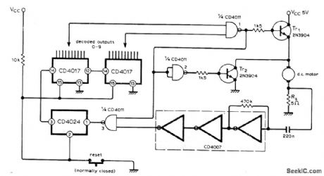
When desired number of revolutions is reached by DC motor, as determined by preset counter, Tr1, is turned off to interrupt path to 5-V motor supply, while TR2 is turned on to brake motor rapidly. Voltage developed across 5-ohm resistor Rs, in series with motor contains frequency component related to speed of rotation and number of armature coils. This signal is amplified by CD4007 CMOS inverter for feeding to counters through signal-squaring inverters. Counter out-puts are decoded by gate 1. Motor slowdown by heavy loads does not affect accuracy of revolution-counting.-R. McGillivray, Motor Revolutions Control, Wireless World, Jan. 1977, p 76. (View)
View full Circuit Diagram | Comments | Reading(1089)
Simple_electronic_control_of_motors
Published:2009/7/21 22:07:00 Author:Jessie
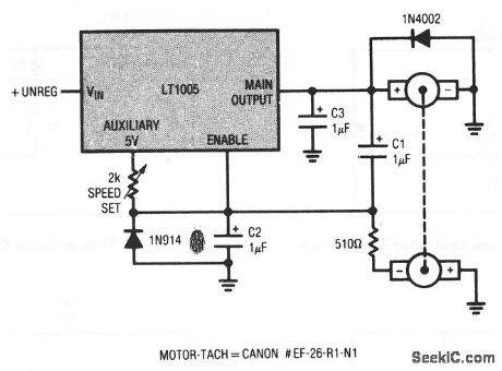
This circuit shows how a simple switch-mode motor controller can be made using an LT1005 multifunction regulator. Motor speed is set by the 2-kΩ pot at the Auxiliary pin of the LT1005. The motor-tach shown has a shaft-torque rating of 20 gram-cMs at 3300 rpm (View)
View full Circuit Diagram | Comments | Reading(796)
SHUNT_MODE_SPEED_CONTROL
Published:2009/7/7 2:52:00 Author:May
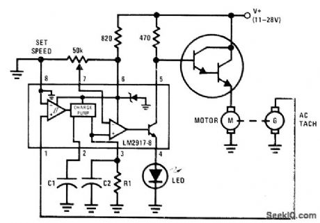
AC tachometer on shaft of DC motor sernves as input for National LM2917N-8 IC acting as shunt-mode regulator with LED indicator. Output of Darling-ton power transistor provides analog drive to motor. As motor speed approaches reference level set by values chosen for R1, C1, and C2, AC current to motor is proportionately reduced so TACH motor comes gradually up to speed and is maintained there without operating in switching mode . Advantage of this arrangement is absence of electric noise normally generated during switching-mode operation.- Linear Applications, Vol. 2, National Semiconductor, Santa Clara, CA, 1976, AN-162 p 10-11. (View)
View full Circuit Diagram | Comments | Reading(3722)
INDUCTIVE_TELEMETRY_FOR_ROTATING_TEST_FIXTURE
Published:2009/7/21 22:21:00 Author:Jessie
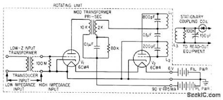
Transducer, oscillator, modulator, and battery supply rotate with device under test. Carrier frequency of 1 Mc, modulated over range of 200 to 10,000 cps, is transferred inductively from rotating output coils L1-L2 to stationary pickup coils.-H. Baumann, Inductive Telemetry Improves Spin-System Measurements, Electronics, 36:46, p 41-42. (View)
View full Circuit Diagram | Comments | Reading(753)
ADJUSTABLE_THRESHOLD_TEMPERATURE_ALARN
Published:2009/7/7 2:35:00 Author:May
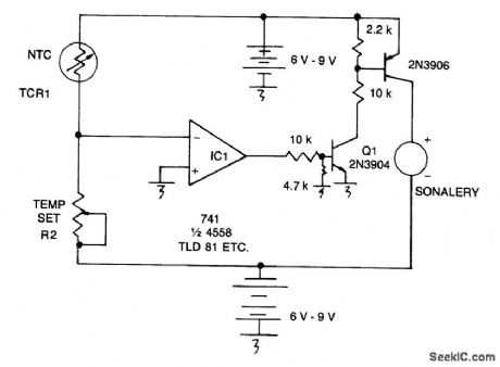
When R1 increases as temp decreases, the output of IC1 goes positive, turning on Q1. Q1 conducts and causes Q2 to conduct, turning on the audible alarm. The threshold is set with potentiometer R2. (View)
View full Circuit Diagram | Comments | Reading(1173)
TEMPERATURE_ALARM
Published:2009/7/7 2:34:00 Author:May
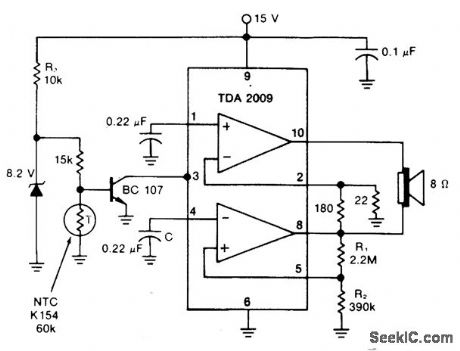
The mute pin of this dual audio amplifter is so used as the trigger for a one chip high-temperature alarm. One-half of the IC is connected as an oscillator and the other boosts the audio alarm outputs to 10W. (View)
View full Circuit Diagram | Comments | Reading(978)
DUAL_TIMER_CHIP_CONTROLS_TEMPERATURE_WHILE_MONITORING_LIQUID_LEVEL
Published:2009/7/7 2:32:00 Author:May
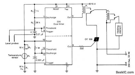
One-half of a 556 dual timer monitors the temperature of a liquid bath, controlling a heating element that maintains temperature within ±2℃ over a 32℃- 200℃ range.The other half monitors the liquid level, disconnecting the heater when the level drops below a preset point. (View)
View full Circuit Diagram | Comments | Reading(1075)
FACSIMILE_PHASE_CONTROL
Published:2009/7/7 2:31:00 Author:May

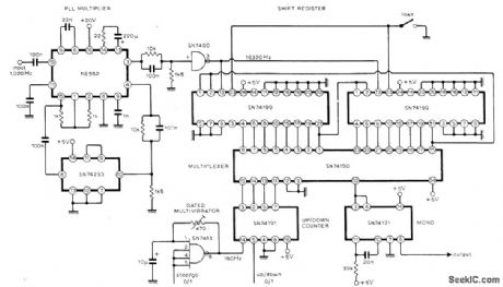

Circuit provides accurate phasing of 51-polpair phonic/synchronous motor in facsimile transmitter, and can readily be adapted for similar applications. A 16-stage shift register loaded with 1 bit and connected as ring counter is clocked at 16 times required drive motor frequency. This gives pulse train with 1:15 mark-space ratio and repetition rate equal to drive frequency. Multiplexer used as single-pole 16-way switch can select output for any stage of shift register; each clockwise switch step gives 360/16 or 22.5° phase advance. Article describes circuit operation in detail-P. E. Baylis and R. J. Brush, Synchronous-Motor Phase Control, Wireless World, April 1976, p 62. (View)
View full Circuit Diagram | Comments | Reading(1530)
LEAKAGE_TESTER
Published:2009/7/21 22:31:00 Author:Jessie
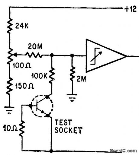
Operational trigger trips when transistor leakage is above 5 ma. Response time is 40 millisec.-P. Lefferts, Operational Trigger For Precise Control, Electronics, 37:28, p 50-55. (View)
View full Circuit Diagram | Comments | Reading(939)
CASSETTE_DRIVE_CONTROLLER
Published:2009/7/7 2:08:00 Author:May
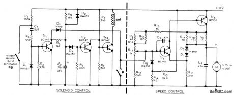
Used in high-quality stereo cassette deck operating from AC line or battery. Combines current source for cassette-retaining solenoid with speed control for drive motor. As motor turns, associated motor-driven pulse-generating switch keeps Tr1, conducting; this cuts off Tr2 and allows current to flow through Tr3 for energizing solenoid. When motor stops, pulse-generating switch also stops and Tr1 stops con-ducting. After 3-s delay determined by C2 and R5, Tr2 conducts and solenoid is deenergized, releasing cassette. In speed control circuit, Tr5 acts as constant-current source for motor, using feedback from its collector to base of Tr4 Back EMF developed by motor is applied to emitter of Tr4 reducing its forward bias and reducing current In the base of Tr5, so as to stabilize motor Article gives all other circuits of cassette deck and describes operation in detail.-J. L. Linsley Hood, Low-Noise, Low-Cost Cassette Deck, Wireless World, Part 3-Aug.1976,ρ55-56(Part 1-May 1976,p 36-40, Part 2-June 1976.p62-66.) (View)
View full Circuit Diagram | Comments | Reading(1321)
Precision_programmable_timers_using_the_Intersil_8240_8250_16_pin_DIP
Published:2009/7/21 22:29:00 Author:Jessie
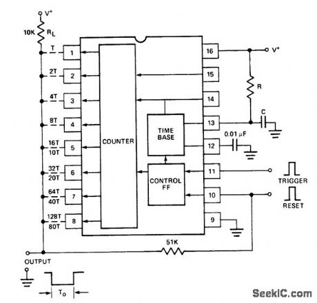
Precision programmable timers using the Intersil 8240/8250 16-pin DIP. The timer is used in the monostable mode. The output is normally high and goes low to trigger an input. Components R and C at pin 13 determine the time cycle. The timing duration, TO is equal to NBC, where R and C are component values and N is a number between 1 and 255. Integer N is determined by the combination of pins 1 through 8 connected to the output bus. The 8250 can be programmed for numbers between 1 and 99. The numbers shown on the schematic adjacent to pin 1 through 8 are the respective N integers, with the upper ones for the 8240 and the lower ones for the 8250 (courtesy Intersil, Inc.). (View)
View full Circuit Diagram | Comments | Reading(1082)
TIME_BASE_GENERATOR
Published:2009/7/21 22:28:00 Author:Jessie
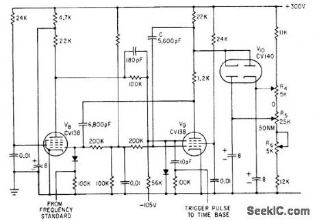
Variable time delay V8-V9 permits selecting portions of cro display in pulse-echo cable fault finder. Adjustment range is 190 to 1,140 microsec, or 10 to 60 nautical miles.-F. Jones and J. H. Reyner, Compact New Instrument Finds Undersea Cable Faults, Electronics, 35:37, p 48-50. (View)
View full Circuit Diagram | Comments | Reading(1222)
WIDEBAND_ACTIVE_PHASE_SHIFTER
Published:2009/7/21 22:27:00 Author:Jessie
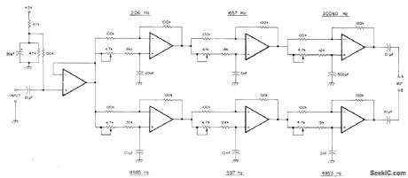
Active audio phase-shift network uses two LM324 quad opamps to provide equal amplitude outputs differing in phase by 90°±2° from 100 Hz to 10 kHz. Each stage is adjusted with 4.7K trim-pot to give 90° phase shift at frequency shown on diagram. Align with audio oscillator and CRO or phase meter. Operates from single 5-V supply. Overall gain of entire circuit is unity.-R.Harrison, A Review of SSB Phasing Techniques, Ham Radio, Jan. 1978, p 52-62. (View)
View full Circuit Diagram | Comments | Reading(4472)
20_KC_WIRE_TRACING_MVBR
Published:2009/7/21 22:27:00 Author:Jessie
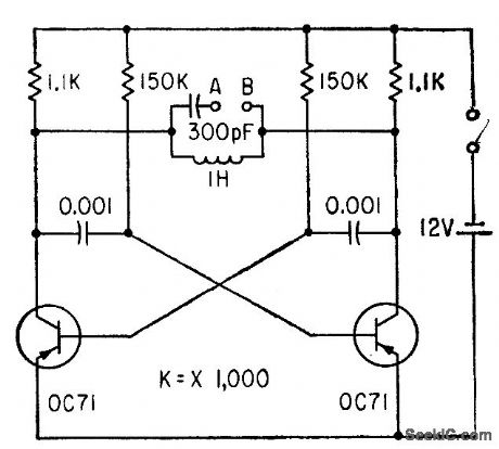
Used as signal source for identifying particular wire at midpoint in cable, for splicing. Ends of wire are connected between A and B, to become part of parallel-tuned circuit of astable mvbr. Tiny probe coil with amplifier is then used to locate wire carrying 20-kc signal.-J. S. Rushton, Probe Identifies Cable Wiring, Electronics, 34:9, p 51. (View)
View full Circuit Diagram | Comments | Reading(682)
SERIES_MOTOR_SPEED_CONTROL
Published:2009/7/7 1:45:00 Author:May
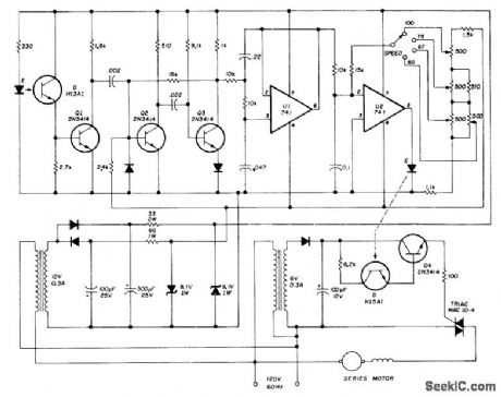
Adjustable-speed solid-state motor drive replaces governor in Kleinschmidt RTTY page printer, to give knob-controlled speed range of 60 to 100 WPM.Notched (33-slot) sheet-aluminum disk serving as pulse wheel is mounted on motor shaft and rotates in gap bemoan LED and phototransistor of GE H13A1 optical coupler to form motor-speed sensor or tachometer. Pulses from tachometer, squared by Q1, trigger mono MVBR Q2-Q3 which converts signal to constant-amplitude constant-width pulses having repetition rate proportional to motor speed. Opamp U1 forms three-pole Butterworth active filter that develops required average DC voltage from pulse train. Output current of U1 is compared to reference current derived from speed control circuit, for switching U2 sharply on and off as speed varies above and below desired value. U2 in turn switches motor on and off through H15A1 optical coupler and Q4 in gate circuit of triac. Second coupler isolates control circuit from AC line.-K. H. Sucker, Electronic Speed Control for RTTY Machines, Ham Radio, Aug.1974,p50-54. (View)
View full Circuit Diagram | Comments | Reading(1131)
DC_MOTOR_SPEED_CONTROLLER
Published:2009/7/7 1:39:00 Author:May
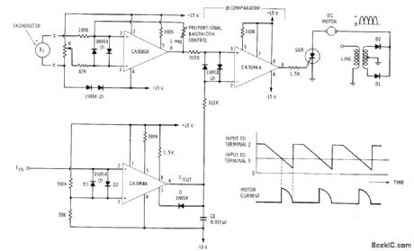
Tachometer driven by motor produces output voltage proportional to speed for application to CA3080A voltage comparator after rectification and filtering. Output of CA3080A is applied to upper CA3094A phase comparator that is receiving reference voltage from another CA3094A connected as ramp generator. Output of phase comparator triggers SCR in motor circuit. Amount of motor current is set by time du-ration of positive signal at pin 6, which in turn is determined by DC voltage applied to pin 3 of phase comparator by error detector. Circuit action serves to maintain constant motor speed at value determined by position of pot R. Input to ramp generator is pulsating DC voltage used to control rapid charging of C1 and slower discharging to form ramp.-E. M. Noll, Linear IC Principles, Experiments, and Projects, Howard W. Sams, Indianapolis, IN, 1974, p 321-323. (View)
View full Circuit Diagram | Comments | Reading(1759)
Long_time_delay_power_switch_for_porch_or_garage
Published:2009/7/21 22:49:00 Author:Jessie
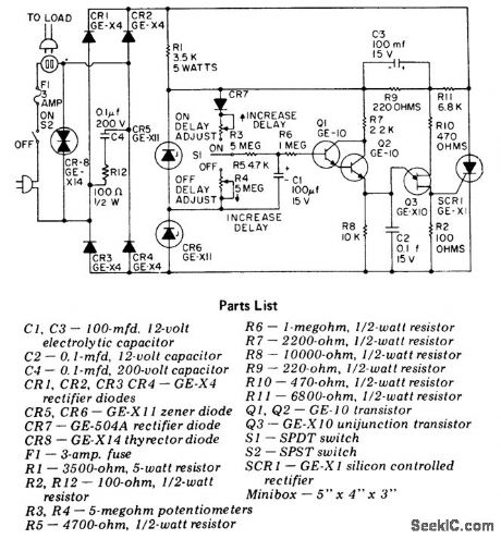
Long time delay power switch for porch or garage. The circuit can handle loads up to 500 watts (courtesy General Electric Company). (View)
View full Circuit Diagram | Comments | Reading(645)
LOW_COST_TRANSISTOR_TESTER
Published:2009/7/21 22:31:00 Author:Jessie
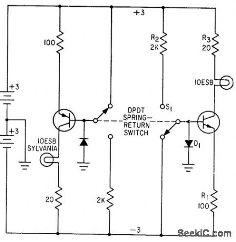
Indicates, in one simple operation, whether transistor has had catastrophic failure and, if not, whether it can provide minimum data (gain) of 20 at 30 ma. Test circuit is inverter with emitter degeneration resistor R1 providing control of collector current during warm up of indicator lamp.-E. H. Sommerfield, Simple Transistor Tester Uses Lamp for Indicator, Electronics, 34:36, p 80. (View)
View full Circuit Diagram | Comments | Reading(764)
| Pages:132/312 At 20121122123124125126127128129130131132133134135136137138139140Under 20 |
Circuit Categories
power supply circuit
Amplifier Circuit
Basic Circuit
LED and Light Circuit
Sensor Circuit
Signal Processing
Electrical Equipment Circuit
Control Circuit
Remote Control Circuit
A/D-D/A Converter Circuit
Audio Circuit
Measuring and Test Circuit
Communication Circuit
Computer-Related Circuit
555 Circuit
Automotive Circuit
Repairing Circuit