
Circuit Diagram
Index 1000
SSB_DETECTOR
Published:2009/7/21 22:18:00 Author:Jessie

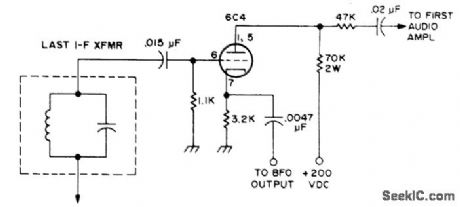
Can be switched in and out of most tube-type AM receivers for use in place of regular detector stage Requires stable BFO.-Novice Q&A,73 Magazine, March 1977,p187. (View)
View full Circuit Diagram | Comments | Reading(893)
660_AND_1000_Hz_FOR_SSB_TESTING
Published:2009/7/21 22:06:00 Author:Jessie
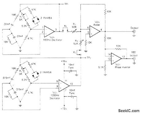
Produces two audio frequencies with all harmonics and cross products down 40 dB or more, as required for accurate testing of amateur SSB equipment. Two sections of Raytheon 4136D quad opamp serve as Wien-bridge audio oscillators, one at 1000 Hz and one at 660 Hz. Silicon signal diodes in each bridge act as nonlinear stabilization elements. Third section of opamp adds sine waves, and fourth section is simple inverter with gain of n for push-pull or balanced output. With all four pots at midvalue, adjust R2 for 12 V P-P at TP2 and adjust R4 for 12 V P-P at TP2. Open X2 and adjust R3 to give 12 V P-P from either output terminal to ground, then close X2 and repeat for X1 and R4. Output should now be 660 and 1000 Hz added linearly as required, with no cross-products. Use regulated ±15 V supply.-H. Olson, A One-Chip, Two Tone Generator, CQ, April 1974, p 48-49. (View)
View full Circuit Diagram | Comments | Reading(1201)
Count_by_5_counter_using_an_ADC1100_dual_slope_A_D_convener
Published:2009/7/21 22:05:00 Author:Jessie
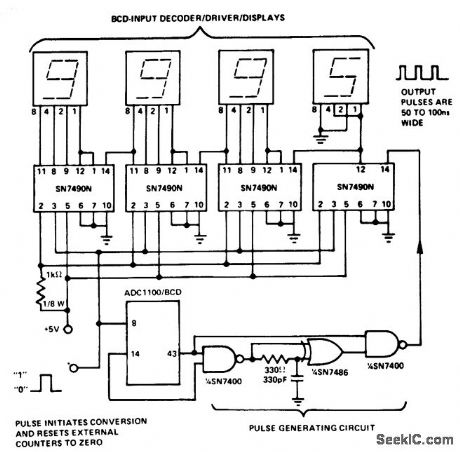
Count-by-5 counter using an ADC1100 dual-slope A/D convener (courtesy Analog Devices, Inc.). (View)
View full Circuit Diagram | Comments | Reading(1526)
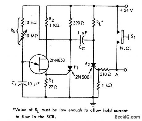
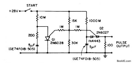
SIMPLE_TIME_DELAY_CIRCUIT_USING_TWO_SCRs
Published:2009/7/7 3:33:00 Author:May
View full Circuit Diagram | Comments | Reading(642)
IME_DELAY_WITH_CONSTANT_CURRENT_CHARGING
Published:2009/7/7 3:29:00 Author:May
View full Circuit Diagram | Comments | Reading(764)
EIGHT_DIGIT_MICROPROCESSOR_DISPLAY
Published:2009/7/7 3:29:00 Author:May
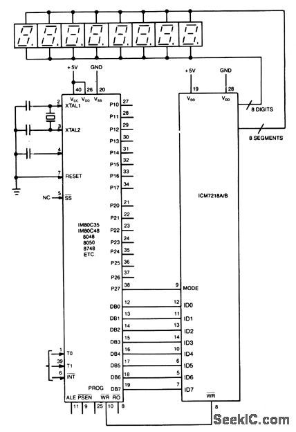
Display interface uses the ICM7218A/B with an 8048 family microcontroller. The 8-bit data bus (DB0/ DB7-ID0/ID7) transfers control and data information to the 7218 display interface on successive WRITE pulses. The mode input pins on the microcontroller. When mode is high, a control word is transferred; when mode is low, data is transferred. Sequential locations in the 8-byte static memory are automatically loaded on each successive WRITE pulse. After eight WRITE pulses have occurred, further pulses areignored until a new control word is transferred.
(View)
View full Circuit Diagram | Comments | Reading(1161)
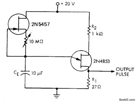
HOUR_TIME_DELAY_SAMPLING_CIRCUIT
Published:2009/7/7 3:29:00 Author:May

The circuit lowers the effective peak current of the output PUT, Q2. By allowing the capacitor to charge with high gate voltage and periodically lowering gate voltage, when Q1 fires, the timing resistor can be a value which supplies a much lower current than Ip. The triggering requirement here is that minimum charge to trigger flow through the timing resistor during the period of the Q1 oscillator. This is not capacitor size dependent, only capacitor leakage and stability dependent. (View)
View full Circuit Diagram | Comments | Reading(760)
ULTRA_SIMPLE_LEVEL
Published:2009/7/7 3:26:00 Author:May
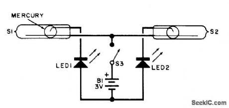
This electronic level uses two LED indicators instead of an air bubble. If the surface is tilted to the right, one LED lights; if it's tilted to the left, the other LED lights. When the surface is level, both LEDs light. It uses two unidirectional mercury switches, S1 and S2. The unidirectional mercury switch has one long electrode and one short, angled electrode. The pool of mercury rides on the long electrode and makes contact between the two electrodes if the unit is held in a horizontal position. (View)
View full Circuit Diagram | Comments | Reading(651)
UP_TO_SPEED_LOGIC
Published:2009/7/7 3:26:00 Author:May
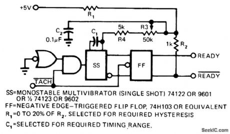
Simple speed-sensing circuit fed by tachometer pulses makes READY output high when rotating device reaches desired minimum or threshold speed. Single-action triggering eliminates instability at decisionpoint. Circuit also provides hysteresis, for separating pull-in and drop-out points any desired amount as determined by ratio of R1 to R2 in timing network. Article covers circuit operation and gives timing diagram.-W. Bleher, Circuit Indicates Logic Ready, EDN Magazine, March 5, 1974, p 72 and 74. (View)
View full Circuit Diagram | Comments | Reading(795)
FET_ADAPTER_FOR_CURVE_TRACER
Published:2009/7/21 21:59:00 Author:Jessie

Used to convert input current steps from Tektronix 575 or other curve tracer lo output voltage steps for let gate.-R. Williams, Adapter for Curve Tracer Tests FET's at High Voltage, Electronics, 39:5, p 104-105. (View)
View full Circuit Diagram | Comments | Reading(2008)
DIFFERENTIAL_CAPACITANCE_MEASUREMENT_CIRCUIT
Published:2009/7/7 3:25:00 Author:May
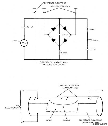
A bubble vial with external aluminum-foil electrodes is the sensing element for a simple indicating tiltmeter. To measure bubble displacement, a bridge circuit detects the difference in capacitance between the two sensing electrodes and the reference electrode. Using this circuit, a tiltmeter level vial with 2 mm deflection for 5 arc-seconds of tilt easily resolves 0.05 arc-second. The four diodes are CA3039, or equivalent. (View)
View full Circuit Diagram | Comments | Reading(1604)
DIGITAL_NOISEMAKER
Published:2009/7/7 3:25:00 Author:May
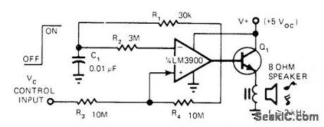
Simple sound-effect generator for video games, electronic cash registers, and electronic toys uses one-fourth of LM3900 quad opamp chip as 2-kHz signal generator that can be turned on or off by input control voltage. Suitable for applications that do not require pure sine wave. Output transistor O1, needed with low-impedance voice coil, is not critical as to type. For smaller acoustic output, Q1 can be replaced by 100-ohm resistor if 100-ohm voice coil is used, to avoid overloading IC.-T. Frederiksen, Build a Transformerless Tone Annunciator, EDN Magazine, April 5, 1977, p141-142. (View)
View full Circuit Diagram | Comments | Reading(686)
MARKER_PULSE_GENERATOR
Published:2009/7/21 21:58:00 Author:Jessie
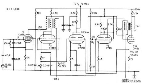
Crystal oscillator V1triggers blocking oscillator V2 to produce sharp pulses at 19.microsec intervals. These feed mono V4, whose output triggers blocking oscillator V5 to give larger pulse every 190 microsec for dud-beam scope of pulse-echo cable fault finder.-F. Jones and J. H. Reyner, Compact New Instrument Finds Undersea Cable Faults, Electronics, 35:37, p 48-50. (View)
View full Circuit Diagram | Comments | Reading(0)
TILTMETER_INDICATES_SENSE_OF_SLOPE
Published:2009/7/7 3:24:00 Author:May
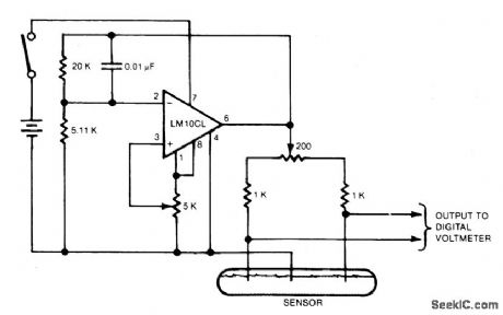
Electrodes are immersed in an electrolyte that remains level while the sensor follows the tilt of the body on which it is placed, more of one outer electrode and less of the other are immersed and their resistances fall or rise, respectively. The resistance change causes a change in the output voltage of the bridge circuit. The sensor forms the two lower legs of the bridge, and two 1000 ohm metal film resistors and a 200 ohm ceremet balance potentiometer form the two upper legs. In preparation for use, the bridge is balanced by adjusting the balance potentiometer so that the bridge output voltage is zero when the sensor is level. The bridge input voltage (dc excitation) is adjusted to provide about 10 millivolts output per degree of slope, the polarity indicating the sense of the slope. This scaling factor allows the multimeter to read directly in decrees if the user makes a mental shift of the meter decimal point. The scaling-factor calibration is done at several angles to determine the curve of output voltage versus angle. (View)
View full Circuit Diagram | Comments | Reading(1316)
XOR_GATE_UP_DOWN_COUNTER
Published:2009/7/7 3:24:00 Author:May
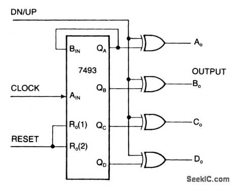
One can transform an ordinary binary counter, such as a 7493, into an up/down counter with mode control by adding XOR gates 7486 to the counter's outputs. The circuit counts up when the DN/UP line is low and down when the DN/UP line is high.
To use the 7493 counter to count out its maximum count length of 0 - 15, connect the QA output to the BIN input and apply clock pulses to the AIN input. The reset input, when high, inhibits the count inputs and simultaneously retums the outputs AO through DO to low in the up-count mode or 15 in the down-count mode. For normal counting, the reset input must be low. 0ne can easily cascade this counter by feeding the QD line to the clock input of a succeeding counter.
(View)
View full Circuit Diagram | Comments | Reading(3816)
100_MHz_multifunction_counter_using_the_Intersil_ICM7226A_40_pin_DIP
Published:2009/7/21 21:57:00 Author:Jessie
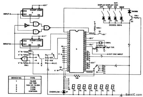
100 MHz multifunction counter using the Intersil ICM7226A 40-pin DIP. This circuit uses a divide-by-10 percaler in the frequency counter mode (courtesy Intersil, Inc.). (View)
View full Circuit Diagram | Comments | Reading(2134)
CENTIGRADE_THERMOMETER_0℃_100℃
Published:2009/7/7 3:23:00 Author:May
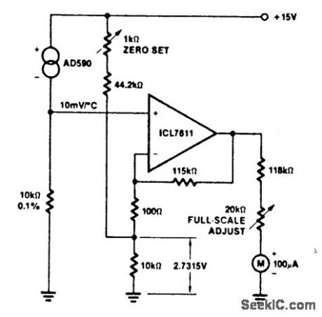
The ultra-low bias current of the ICL7611 allows the use of large-value gain-resistors, keeping meter-current error under 1/2%, and therefore saving the expense of an extra meter-driving amplifier. (View)
View full Circuit Diagram | Comments | Reading(572)
LIQUID_BATH_THERMOSTAT_FOR_O01°_CONIROL
Published:2009/7/21 21:55:00 Author:Jessie
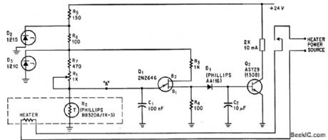
Based on thermistor R2, which has linear temperature coefficient of -6% per degree C from 15 to 35 degree C. R2 is one element in relaxation oscillator also consisting of Q1, C1, R1, R3, and R4.-K. von der Geer, Control is Accurate to 0.01℃, Electronics, 39;12, p 111. (View)
View full Circuit Diagram | Comments | Reading(640)
NULL_INDICATING_DIODE_THERMOMEIER
Published:2009/7/21 21:53:00 Author:Jessie
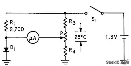
Microammeter serves as null indicator. When potentiometer is adjusted for zero current, arm of potentiometer indicates temperature value directly. Values of R3 and R4 are chosen to place 25℃ range anywhere from near absolute zero to about 40℃.-L. E. Barton, Measuring Temperature with Diodes and Transistors, Electronics, 35:18, p 38-40. (View)
View full Circuit Diagram | Comments | Reading(690)
TEMPERATURE_MONITOR
Published:2009/7/21 21:52:00 Author:Jessie
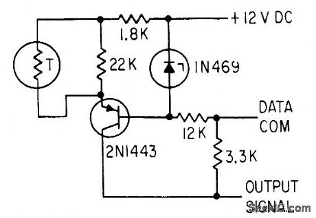
Senses variations in ambient temperature near telemetry detector in space probe. Zener diode maintains constant voltage on transistor base.-S. Chase, Jr. and F. Schwarz, Mariner II Instrumentation:What Will It See on Venus?, EJectronics, 35:50, p 42-45. (View)
View full Circuit Diagram | Comments | Reading(2344)
| Pages:1000/2234 At 209819829839849859869879889899909919929939949959969979989991000Under 20 |
Circuit Categories
power supply circuit
Amplifier Circuit
Basic Circuit
LED and Light Circuit
Sensor Circuit
Signal Processing
Electrical Equipment Circuit
Control Circuit
Remote Control Circuit
A/D-D/A Converter Circuit
Audio Circuit
Measuring and Test Circuit
Communication Circuit
Computer-Related Circuit
555 Circuit
Automotive Circuit
Repairing Circuit