
Circuit Diagram
Index 1001
Simple_ac_power_control
Published:2009/7/21 21:43:00 Author:Jessie
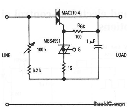
This circuit shows a simple ac full-wave control scheme that uses a triac and SBS. Control is obtained by varying the 100-kΩ pot. Notice that PGK can be omitted when triacs with nonsensitive gates are used. (View)
View full Circuit Diagram | Comments | Reading(869)
Digitally_controlled_time_delay
Published:2009/7/21 21:42:00 Author:Jessie
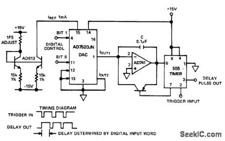
Digitally controlled time delay. This circuit generates a time delay controlled by the digital input of the AD7520. The current fed into the integrator's summing point at OUT 1 is determined by the D/A converter's input. The output of the integrator remains low until the trigger input of the 555tmergoes low. At that time the timer's output goes high, unclamping the output and permitting the integrator to change upward until it reaches 2/3VDD, at which time the timer's output goes low and the integrator is reset to zero. The time delay is D/D1REF×10V, where D is the fractional binary equivalent of the digital input word (courtesy Analog Devices, Inc.). (View)
View full Circuit Diagram | Comments | Reading(768)
BASIC_DIGITAL_THERMOMETER,KELVIN_SCALE_WITH_ZERO_ADJUST
Published:2009/7/7 3:22:00 Author:May
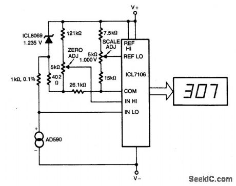
This circuit allows zero adjustment as well as slope adjustment. The ICL8069 brings the input within the common-mode range, while the 5 k ohm pots trim any offset at 218°K (-55℃), and set the scale factor.
(View)
View full Circuit Diagram | Comments | Reading(669)
11_Mc_TEMPERATURE_SENSING_OSCILLATOR
Published:2009/7/21 21:41:00 Author:Jessie
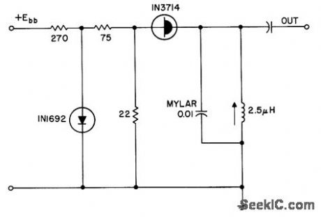
Uses mylar capacitor as main temperature sensing element, with temperature coefficient of 0.5 kc/℃, in tunnel-diode oscillator that translates temperature changes into frequency changes.- Transistor Manual, Seventh Edition, General Electric Co., 1964, p 350. (View)
View full Circuit Diagram | Comments | Reading(687)
STEPPER_MOTOR_DRIVE
Published:2009/7/7 3:21:00 Author:May
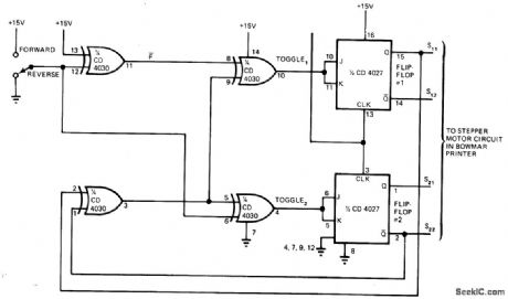
Two CMOS packages provide the four feed signals required for controlling forward/reverse drive of stepper motor for carriage drive and paper advance of Bowmar Model TP 3100 thermal printer. 0ut-puts of flip-flops are above 10V, enough to drive stepper motor directly. Each clock pulse to JK flip-flop advances carriage one step in direction commanded-R Bober. Stepper Drive Circuit Simplifies Printer Control、EDN Magazine , April 5,1976,ρ114.
(View)
View full Circuit Diagram | Comments | Reading(2801)
_DIFFERENTIAL_THERMOMETER
Published:2009/7/7 3:21:00 Author:May
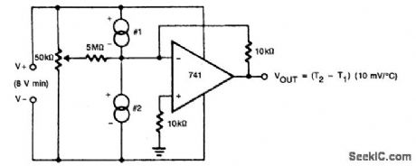
The 50 k ohm pot trims offsets in the devices whether internal or external, so it can be used to set the size of the difference interval. This also makes it useful for liquid-level detection (where there will be a measurable temperature difference). (View)
View full Circuit Diagram | Comments | Reading(679)
THERMISTORS_CORRECT_THRMETEAR_LINEARITY
Published:2009/7/21 21:40:00 Author:Jessie
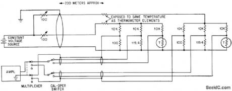
Zero-temperature-coefficient resistors mounted near resistance thermometer element offset variation of lead resistance with temperature.-F. J. Goldwater, Low-Cost Digital System Records Weather Data, Electronics, 37;2, P 34-36. (View)
View full Circuit Diagram | Comments | Reading(677)
20_MHz_TONUBUS_CLOCK_PHASE_LOCK
Published:2009/7/7 3:20:00 Author:May
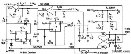
The 20-MHz clock phase-locks to Apple's Mac II 10-MHz NuBus clock. It uses a simple, inexpensive CMOS circuitry to generate 10- and 20-MHz square waves. The output duty cycle settings are insensitive to VCC variations. The input to the circuit is a NuBus clock signal with specifications that call for a 75 percent duty cycle at 10 MHz-a square wave that's high for 75 ns and low for the remaining 25 ns. To generate the 20-MHz signal, the circuit produces a 25-ns negative-going pulse, delayed 50 ns from the falling edge of the 10-MHz NuBus clock input at point E. NORing that pulse with the NuBus clock produces the 20-MHz clock at point G. Finally, applying the 25-ns pulse to the set input of a set-reset input, results in a 10-MHz square wave at F.
(View)
View full Circuit Diagram | Comments | Reading(612)
4_digit_unit_counter_with_BCD_output_using_an_Intersil_ICM7217A_28_pin_DIP
Published:2009/7/21 21:37:00 Author:Jessie
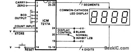
4-digit unit counter with BCD output using an Intersil ICM7217A 28-pin DIP. All that is required is an ICM7217, a power supply and a 4-digit display. Add a momentary switch for reset and an SPDT center-off switch to blank the display or view leading zeros. One more SPDT switch gives you up/down capabilities. With an ICM7217A and a common-cathode calculator-type display this is the least expensive digital counter/display system you can make (courtesy Intersil, Inc.). (View)
View full Circuit Diagram | Comments | Reading(1685)
ELECTRONIC_THERMOMETER
Published:2009/7/7 3:19:00 Author:May
An inexpensive electronic thermometer is capable of measuring temperatures over a range of from -30°F to + 120°F. A diode-connected 2N3904 transistor used as the temperature sensor forms a voltage divider with RI. As temperature increases, the voltage drop across the transistor changes by approximately -1.166 millivolts-per°F. As a result, the current at pin 3 of IC1, a 741 op amp with a gain of 5, decreases as the temperature measured by the sensor increases.A second 741 op amp, IC2 is configured as an inverting amplifier. Resistors R5 and R6 calibrate the circuit. Calibration is also straightforward. When properly done, a temperature of -30°F will result in a meter reading of 0 milliamps, while a temperature of 120°F will result in a meter reading of 1 milliamp. Divide the scale between those points into equal segments and mark the divisions with the appropriate corresponding temperatures. The calibration is completed by placing the sensor in an environment with a known temperature, such as an ice-point bath. Place the sensor in the bath and adjust R6 until you get the correct meter reading. (View)
View full Circuit Diagram | Comments | Reading(5582)
Simple_dc_power_control
Published:2009/7/21 21:37:00 Author:Jessie
This circuit shows a simple dc full-wave control scheme that uses an SCR and an SBS. Control is obtained by varing the 100-kΩ pot. Notice that R1, can be omitted when triacs with nonsensitive gates are used. (View)
View full Circuit Diagram | Comments | Reading(1062)
SIX_TONE_CHIME_
Published:2009/7/7 3:18:00 Author:May
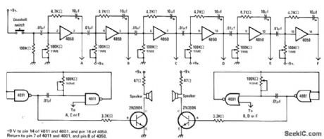
Separate AF oscillators, gated on by six-stage time-delay circuit, generate six different chime tones. Loudspeakers can be mounted so each tone comes from different location in house. When doorbell button is pushed, each tone generator is turned on in sequence for period determined by individual time controls. System operates from 9-V battery, with CMOS logic drawing very little standby current.-J. Sandier, 9 Projects under $9, Modern Electronics, Sept. 1978, p 35-39. (View)
View full Circuit Diagram | Comments | Reading(1963)
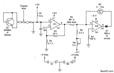
REMOTE_THERMOMETER
Published:2009/7/7 3:18:00 Author:May
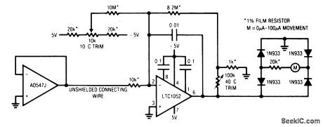
The low output impedance of a closed loop op amp gives ideal line-noise immunity, while the op amp's offset voltage drift provides a temperature sensor. Using the op amp in this way requires no external components and has the additional advantages of a hermetic package and unit-to-unit mechanical uniformity if replacement is ever required.The op amp's offset drift is amplified to drive the meter by the LTC1052. The diode bridge connection allows either positive or negative op amp temperature sensor offsets to interface directly with the circuit. In this case, the circuit is arranged for a + 10℃ to +40℃ output, although other ranges are easily accommodated. To calibrate this circuit, subject the op amp sensor to a +10℃ environment and adjust the 10℃ trim for an appropriate meter indication. Next, place the op amp sensor in a +40℃ environment and trim the 40' adjustment for the proper reading. Repeat this procedure until both points are fixed. Once calibrated, this circuit will typically provide accuracy within ±2℃, even in high noise environments. (View)
View full Circuit Diagram | Comments | Reading(710)
Clcok_timebase_with_1MHz_reference
Published:2009/7/21 21:52:00 Author:Jessie
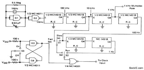
Clcok timebase with 1MHz reference (courtesy Motorola Semiconductor Products Inc.). (View)
View full Circuit Diagram | Comments | Reading(662)
LIMITED_RANGE_DIODE_THERMOMETER
Published:2009/7/21 21:51:00 Author:Jessie
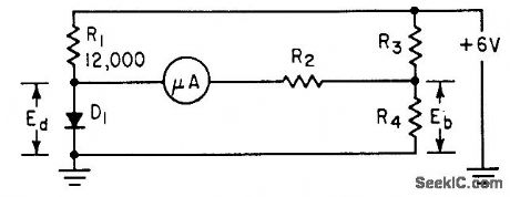
Values of R3 and R4 determine portion of tem perature spectrum to be measured, while R2 determines full-scale temperature value of meter, which may be as low as 25℃. Meter depends on fact that voltage drop across germanium diode is linear function of temperature.-L. E. Barton, Measuring Temperature with Diodes and Transistors, Electronics, 35:18, p 38-40. (View)
View full Circuit Diagram | Comments | Reading(770)
TEMPERATURE_CONTROL
Published:2009/7/21 21:50:00 Author:Jessie
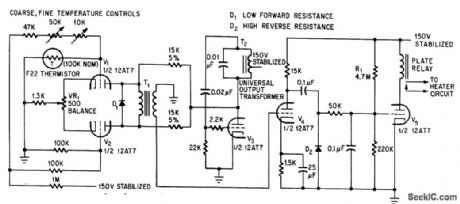
Fast thermal response is obtained with high-resistance thermistor in bridge circuit, feeding chopper V1-V2. V3 is Hartley oscillator operating at about 400 cps, to plate modulate chopper tubes. When bridge is unbalanced by thermister, pulses in secondary ofT1 act through amplifiers V4 and V5 to operate relay. -G. A. R. Trollope, Thermistor Regulator Provides Fast Response, Electronics, 39:5, p 106-107.
(View)
View full Circuit Diagram | Comments | Reading(0)
Time_delay_circuit_with_constant_current_charging_of_timing_circuit_using_a_UJT_and_JFET
Published:2009/7/21 21:48:00 Author:Jessie
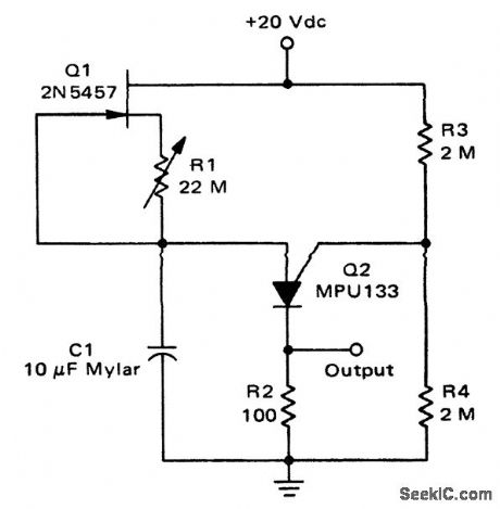
Time delay circuit with constant-current charging of timing circuit using a UJT and JFET. Constant currents of less than 1 μA can easily be obtained that result in time delays up to 10 minutes. (View)
View full Circuit Diagram | Comments | Reading(828)
BATH_TEMPERATURE_CONTROL
Published:2009/7/21 21:48:00 Author:Jessie
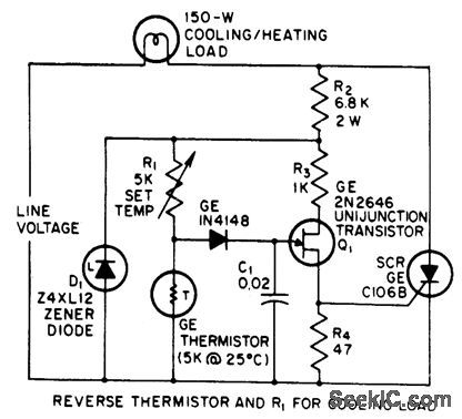
Used to maintain temperature of photographic developer solution constant. When temperature drops, thermistor resistance increases and scr is turned on earlier in each cycle by ujt.-J. Embinder, SCRs in the Consumer Market, EEE, 14:8, p 100-103. (View)
View full Circuit Diagram | Comments | Reading(961)
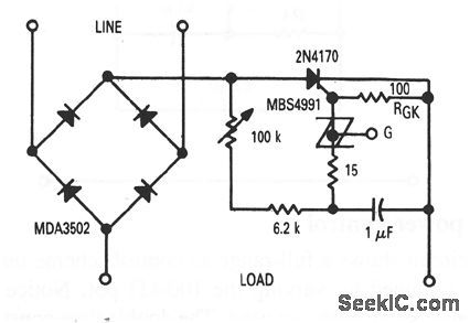
Full_range_ac_power_control
Published:2009/7/21 21:47:00 Author:Jessie

This circuit shows a full-range ac control scheme that uses a triac and SBS. Control is obtained by varying the 100-k Ω pot. Notice thatRGK can be omitted when nonsensitive gates are used. The double time constants of this circuit produce low hysteresis, which thus extends the control range. (View)
View full Circuit Diagram | Comments | Reading(863)
20_minute_long_duration_timer_using_a_PUT
Published:2009/7/21 21:47:00 Author:Jessie
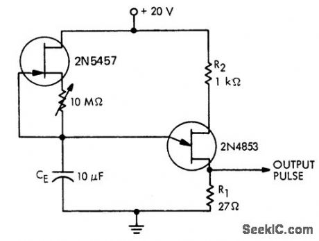
20-minute long-duration timer using a PUT (courtesy Motorola Semiconductor Products Inc.). (View)
View full Circuit Diagram | Comments | Reading(810)
| Pages:1001/2234 At 2010011002100310041005100610071008100910101011101210131014101510161017101810191020Under 20 |
Circuit Categories
power supply circuit
Amplifier Circuit
Basic Circuit
LED and Light Circuit
Sensor Circuit
Signal Processing
Electrical Equipment Circuit
Control Circuit
Remote Control Circuit
A/D-D/A Converter Circuit
Audio Circuit
Measuring and Test Circuit
Communication Circuit
Computer-Related Circuit
555 Circuit
Automotive Circuit
Repairing Circuit