
Circuit Diagram
Index 1019
TRANSFORMER_COUPLED_BASE_MODULATION
Published:2009/7/22 1:19:00 Author:Jessie
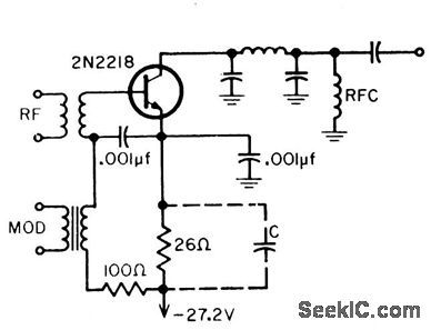
Modulation is in series with r-f signal, so transistor operates in common-emitter con figuration for both r-f and audio. Waveform is good, but modulation power is only 0.7 mw into 900 ohms when audio bypass C is used. Without bypass, modulation power is 1 mw into 200 ohms.-B. Rheinfelder, Modulation Techniques for Transistorized A-M Transmitters, EEE, 11:7, p 54-57. (View)
View full Circuit Diagram | Comments | Reading(823)
SERIES_RESISTOR_PULSE_MODULATOR
Published:2009/7/22 1:18:00 Author:Jessie
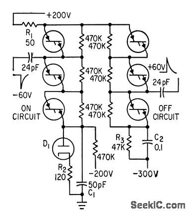
Four, layer diodes with series resistors reduce 350-v,1-cmp pulses to modulate twt and for other applications requiring fast-rise, variable-width, high-current lat-top pulses at repetition rates up to 200 pps.-E. H. Heckman, Three New Approaches to Pulse Modulation, Electronics, 36:18, p 62-64. (View)
View full Circuit Diagram | Comments | Reading(867)
Thyristor_control_with_voltage_feedback
Published:2009/7/22 1:51:00 Author:Jessie
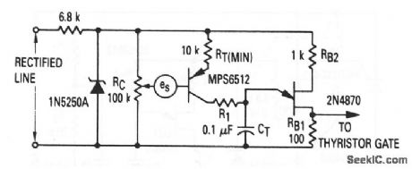
This circuit shows a UJT that is used as a thyristor trigger (with feedback), where the quantity to be sensed is in the form of an isolated feedback dc voltage (such as a tachometer output voltage). The feedback voltage is applied between voltage divider RC and the base of Q1. RC sets the operating point, and thus provides some manual control. (View)
View full Circuit Diagram | Comments | Reading(1240)
GOLF_CARI_IRACTION_DRIVE
Published:2009/7/22 1:50:00 Author:Jessie
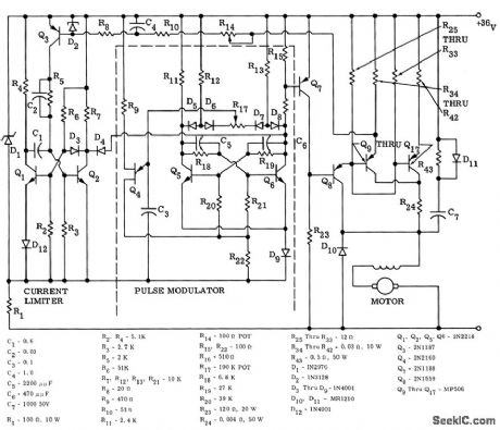
Pulse-width-modulating series motor control was designed to operate motor in Cushman golf cart from 36-v battery supply. Provides 200 amp for climbing steep inclines and up to 300 amp for starting, Eight MP506 transistors in parallel ore used to switch peak motor load. Speed is changed by varying width of pulse that is applied to motor at constant rate, to vary overage motor voltage.-H. F. Weber, Solid-State DC Motor Control for Traction Drive Vehicles, Motorola Application Note AN-189, Mar. 1966. (View)
View full Circuit Diagram | Comments | Reading(1733)
FULL_WAVE_SPEED__REGULATOR
Published:2009/7/22 1:48:00 Author:Jessie
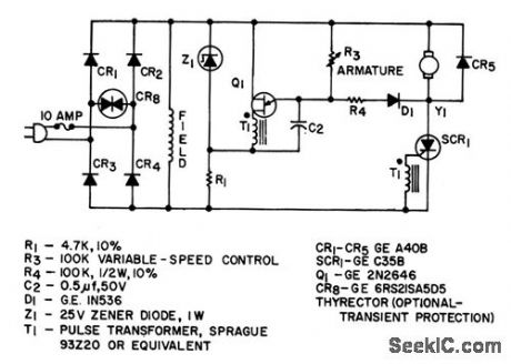
Features closed-loop feedback armature control to regulate speed of 0.5-hp shunt-wound d-c motor over 6:1 range .-“Silicon Controlled Rectifier Mannual,” Third Edition, General Electric Co,164,p145. (View)
View full Circuit Diagram | Comments | Reading(1447)
Thyristor_control_with_feedback
Published:2009/7/22 1:48:00 Author:Jessie
This circuit shows a UJT that is used as a thyristor trigger with both manual and automatic (feedback) control. The feedback-sensing resistor RS can respond to any one of many stimuli, such as heat, light, pressure, moisture, or magnetic fields. The circuit operating point is set manually by RC. As Rs increases, more current flows into CT, the UJT triggers at a smaller phase angle, and more power is applied to the load. Thus, for this circuit, RS must decrease in response to excessive power in the load. If,RS increases with load power, then RS and RC must be interchanged. (View)
View full Circuit Diagram | Comments | Reading(982)
SQUELCH_1
Published:2009/7/22 1:47:00 Author:Jessie
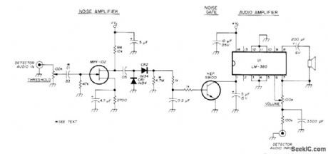
Simple circuit using LM380 audio amplifier IC gives excellent performance. First transistor amplifies random noise which is greater in frequency than normal spectrum of voice during no-signal conditions. CR1 and CR2 rectify noise. Second transistor conducts and clamps U1 off when there is no signal. Increasing value of C1 increases gain of noise amplifier, but small value of C1 makes circuit less susceptible to heavy noise peaks.-R. Harris Another Squelch Circuit, Ham Radio, Oct 1976,p78. (View)
View full Circuit Diagram | Comments | Reading(3509)
ACCELERATION_SENSING_SWITCH
Published:2009/7/22 1:46:00 Author:Jessie
Sensing switch controls Q1, which provides power for accelerometer motor. Q2 and Q3 provide damping by current limiting, to increase ac curacy by one order of magnitude.-F. W.Kear, Dynamic Fluid Switch Senses Acceleration, Electronics, 34:38, p 64-67. (View)
View full Circuit Diagram | Comments | Reading(630)
TWO_PHASE_INDUCTION_MOTOR_DRIVE
Published:2009/7/22 1:45:00 Author:Jessie
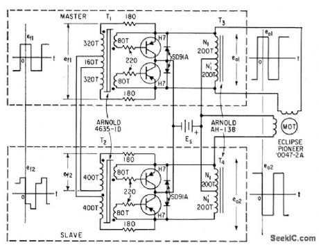
Transistors used as controlled switches in inverter Provide two-phase square-wave output from single d-c source,May also be used with hysteresis-synchronous motors to provide speed under load.-W. H. Card, Four Transistor Inverter Drives Induction Motor, Electronics, 32:8, p 60-61. (View)
View full Circuit Diagram | Comments | Reading(1876)
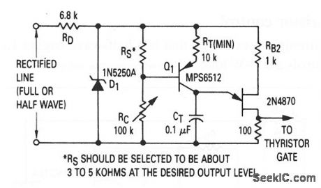
Thyristor_control_with_line_voltage_compensation
Published:2009/7/22 1:44:00 Author:Jessie
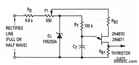
This circuit shows a UJT used as a trigger, where the thyristor must provide a constant output voltage, regardless of line-voltage changes. As line voltage increases, the voltage on the wiper of P1 increases (as does the UJT peak voltage), which increases the CT charge. With a higher charge on CT, the circuit takes more time to trigger, reduces the thyristor conduction angle and maintains the average voltage at a reasonably constant value. (View)
View full Circuit Diagram | Comments | Reading(1309)
FULL_WAVE_PUSH_PULL_FOR_A_C_SERVO_MOTOR
Published:2009/7/22 1:43:00 Author:Jessie
Circuit is identical to full-wave push-pull d-c shunt motor drive except for different arrangement of firing circuit,Limiting resistors R1 and R2 determine standby current.-W. R. Seegmiller, Controlled Rectifiers Drive A-C and D-C Motors,Electronics,32:4,p 73-75. (View)
View full Circuit Diagram | Comments | Reading(716)
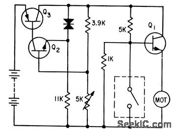
ONE_SOURCE_CONTROL
Published:2009/7/22 1:44:00 Author:Jessie
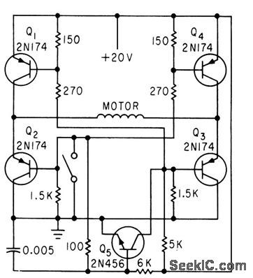
Q5 determines direction of current flow through motor winding, which in turn depends on position of motor control switch. Motor torsion opens switch, and acceleration during slowdown closes switch, to make motor speed proportional to acceleration.-F. W. Kear, D-C Motor Controls Improve System Accuracy, Electronics, 33:41, p 76. (View)
View full Circuit Diagram | Comments | Reading(725)
NOISE_SUPPRESSOR
Published:2009/7/22 1:42:00 Author:Jessie
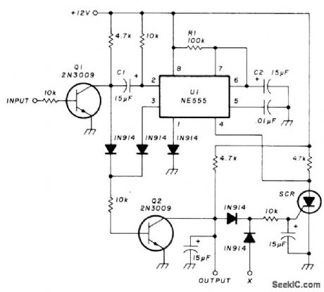
Eliminates repeater squelch tails from receiver having its own squelch, while allowing normal communications to pass through. Circuit goes between receiver squelch gate and point at which squelch acts on audio amplifier, to provide about 3-s delay before turning amplifier on. If received signal disappears before end of delay, radio remains silent and circuit resets itself. If received signal lasts longer than 3 s, as when repeater is interrogated, receiver operation is normal. Designed for receivers using low voltage level to squelch audio amplifier. NE555 timer is wired as mono MVBR that is triggered through inverter a1 each time receiver squelch is tripped, pro-vided SCR is off. SCR type is not critical. Input is taken from squelch gate in receiver.-R. K. Morrow, Jr., Repeater Kerchunk Eliminator for Mobile Rigs, Ham Radio, 0ct. 1977, p 70-71. (View)
View full Circuit Diagram | Comments | Reading(1)
Full-wave_thyristor_control
Published:2009/7/22 1:41:00 Author:Jessie
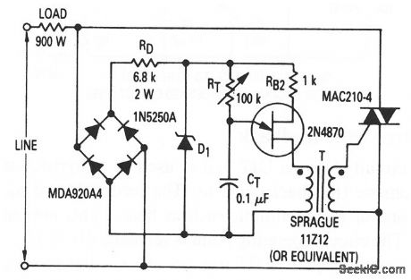
This circuit shows a UJT that is used as a full-wave trigger for a thyristor (a triac),which controls a 900-w load. (View)
View full Circuit Diagram | Comments | Reading(917)
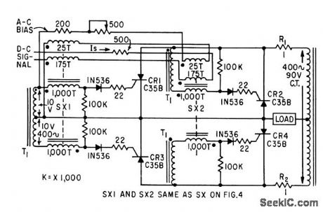
SERIES_ACTUATOR_SOLENOID_DRIVE
Published:2009/7/22 1:41:00 Author:Jessie
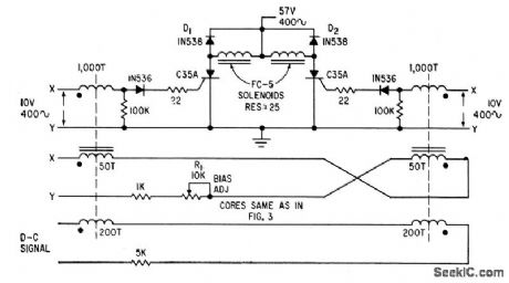
Consists of controlled rectifier in series with each solenoid, and saturable magnetic core firing circuit. Each magnetic core has two control windings, one for adjustment and one for signal. Can also be used to drive d-c split-series motors. Windings of motor then re place solenoids.-W. R. Seepmiller, Controlled Recliners Drive A-C and D.C Motors, Electronics, 32:46, p 73-75. (View)
View full Circuit Diagram | Comments | Reading(870)
100_Hz_CTCSS_OSCILLATOR
Published:2009/7/22 1:41:00 Author:Jessie
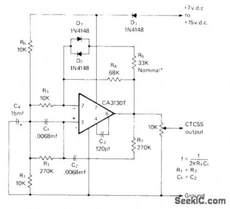
Stable Wien-bridge oscillator provides continuous-tone-coded subaudible squelch (CTCSS) for amateur FM repeater system to protect input from interference on commonly shared channels and add security to input frequency. Tone can be heard in background but does not become irritating. Use film resistors for R1 and R2. C1 and C2 should be polystyrene, polycarbonate, Teflon, or silver mica. Select R5 to give 8-10 V P-P sine wave when operating from 12-V supply. R1 and R2 may be varied slightly to adjust frequency.-D. Dauben, Miniature Solid State Tone Encoders to Replace Reeds, CQ, Dce. 1975, p 42-45 and 76. (View)
View full Circuit Diagram | Comments | Reading(1527)
SQUELCH
Published:2009/7/22 1:39:00 Author:Jessie
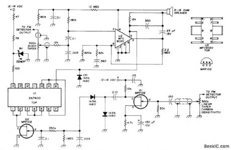
Simple system with sharply de-fined threshold can be added to any FM receiver. Circuit includes conventional IC audio amplifier. Audio is taken from FM detector output by shielded audio line and filtered by U2 to drive loudspeaker. Similar arrangement (below) connects FM detector output to 500K squelch sensitivity control, for amplification by Q1 and rectification. Q2 is turned off at thresh-old level determined by sensitivity control. Q2 then begins logic toggling action through U1.Low on pin 8 of U1 clamps off portion of U2,quieting loudspeaker. Signal carder reverses process, passing audio to loudspeaker. No-signal noise output voltage from FM detector should be at least 0.75 VAC. Circuit eliminates no-signal noise while allowing weakest desired signals to pass.-R. C. Harris, Versatile Squelch-Audio Amplifier for FM Receivers, Ham Radio, Sept. 1974, p 68-69. (View)
View full Circuit Diagram | Comments | Reading(5156)
Half_wave_thyristor_control
Published:2009/7/22 1:38:00 Author:Jessie
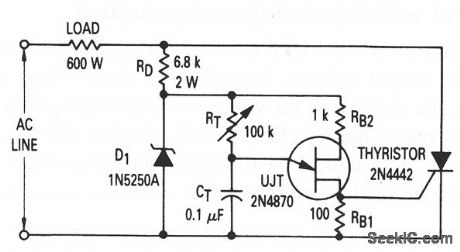
This circuit shows a UJT that is a half-wave trigger for a thyristor (an SCR),which controls a 600-W load. (View)
View full Circuit Diagram | Comments | Reading(1295)
SQUELCH_ADAPTER
Published:2009/7/22 1:36:00 Author:Jessie
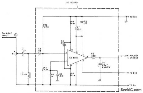
Designed for use with any solid-state receiver having discrete transistor audio stages. Uses RCA CA3018 IC containing four NPN transistors, connected here to give noise amplifier that drives DC bias control stage acting on switching transistor for AF stages of receiver (one transistor in IC is unused). Designed for circuits having positive supply-voltage ground; for negative-ground circuits, reverse polarity of 06 and connect C4 to negative ground. R1 should be about 5 times resistance of volume control in receiver. B+1 should not exceed +12 VDC and can be as low as 6V. B+2 is 3.5 V. Squelch is used chiefly when monitoring police bands on radio.-P. A. Lovelock, The Postage Stamp Squelcher, 73 Magazine, May 1975, p 103-105. (View)
View full Circuit Diagram | Comments | Reading(1208)
ONE_TUBE_SQUELCH
Published:2009/7/22 1:34:00 Author:Jessie
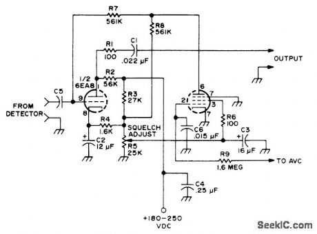
Designed for insertion between second detector and AF volume control in tube-type AM receiver having AVC and well-filtered DC supply, to suppress noise when there is no input signal, such as when tuning between stations.-Circuits, 73Magazine, May 1977, p 31. (View)
View full Circuit Diagram | Comments | Reading(875)
| Pages:1019/2234 At 2010011002100310041005100610071008100910101011101210131014101510161017101810191020Under 20 |
Circuit Categories
power supply circuit
Amplifier Circuit
Basic Circuit
LED and Light Circuit
Sensor Circuit
Signal Processing
Electrical Equipment Circuit
Control Circuit
Remote Control Circuit
A/D-D/A Converter Circuit
Audio Circuit
Measuring and Test Circuit
Communication Circuit
Computer-Related Circuit
555 Circuit
Automotive Circuit
Repairing Circuit