
Circuit Diagram
Index 1018
10_V_SIREN_CHIP
Published:2009/7/22 1:14:00 Author:Jessie
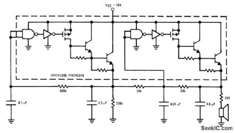
One section of National MM74C908/MM74C918 dual CMOS driver is used as audio VCO and other section as voltage ramp generator that varies frequency of VCO. Combination gives siren effect at low cost, with output current up to 250mA for driving loudspeaker.- CMOS Databook, National Semiconductor, Santa Clara, CA, 1977, p 5-38-5-49. (View)
View full Circuit Diagram | Comments | Reading(885)
TEMPERATURE_CONTROLLING_CIRCUIT
Published:2009/7/6 20:59:00 Author:May
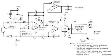
The circuit switches the current to an electrical heater on and off to maintain the temperature of a room at 25 ±0.5℃. The temperature sensor is a thermistor which provides a differential input (for reduced noise) to an operational amplifier. A 5 kilohm potentiometer is used to adjust the set point through a voltage divider; a value of 2.17 kilohms yields the 25℃ setting. A second operational amplifier is connected as an inverting differential-input comparator. The output of operational amplifier 2 controls the electrical heater through a zero-crossing solid-state relay. A transistor/transistor-logic (TTL) gate adjusts the output to the proper level for the relay. A thermal switch is placed in series with the heater and the ac supply for safety in case of thermal runaway. A third operational amplifier monitors the output of the thermistor, providing a signal to a computer for data logging.
(View)
View full Circuit Diagram | Comments | Reading(854)
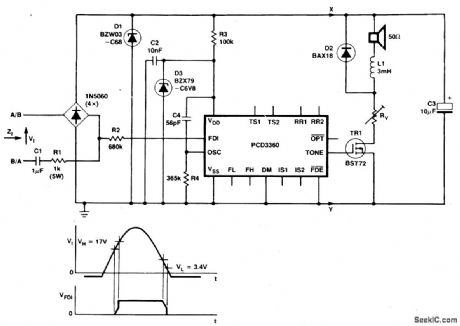
PCD3360_Ringer_With_PXE_Transducer_
Published:2009/7/6 20:57:00 Author:May
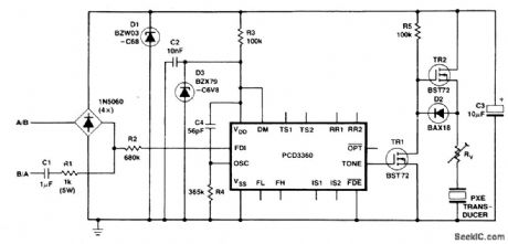
Two BST72 transistors provide an output voltage swing almost equal to the voltage at C3. Pins IS1 and IS2 are inoperative because DM = HIGH. Volume control is possible using resistor RV.
(View)
View full Circuit Diagram | Comments | Reading(1199)
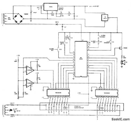
DIGITAL_CLOCK_WITH_ALARM
Published:2009/7/6 20:57:00 Author:May
View full Circuit Diagram | Comments | Reading(2092)
DC_CONTROL_BY_TTL_I_O
Published:2009/7/6 20:55:00 Author:May
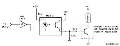
Output of microprocessor drives LED of photocoupler through one section of 7414 hex Sch mitt-trigger-input inverter. Phototransistor switches power transistor or power Darlington on and off for control of direct current through load. With transistor having current gain of 30 and 20-mAcontrol cur-rent, load current can be 500 mA. With power Darlington having higher current gain, load can be several amperes. Since power de-vice is either off or saturated, heatsink can be small.-M. Boyd, Interfacing Tips, Kilobaud, Feb. 1978, p 72-74. (View)
View full Circuit Diagram | Comments | Reading(946)
SCR_RING_COUNTER_DRIVES_HYSTERESIS_MOTOR
Published:2009/7/22 1:28:00 Author:Jessie
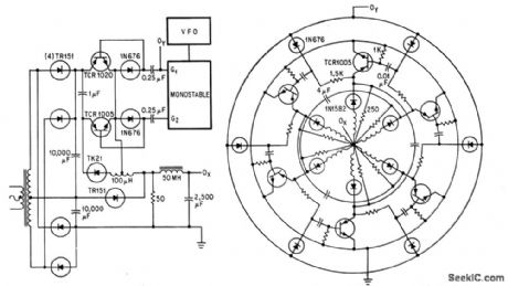
Speed range of 1,200 to 18,000 rpm is obtained with 400-cps, six-pole fractional-hp hysteresis motor by modifying scr ring counter to work in switching mode. Series rectifiers prevent spurious modes during commutation. Output OX of circuit at left goes to centet of circular configuration, and OY goes to outer circle.-R. H. Murphy, Static Alternator Controls Three-Phase Motor, Electronics, 37:15, p 30-33. (View)
View full Circuit Diagram | Comments | Reading(980)
CURRENT_CONTROLLED_SQUARE_TRIANGLE_GENERATOR
Published:2009/7/6 20:55:00 Author:May
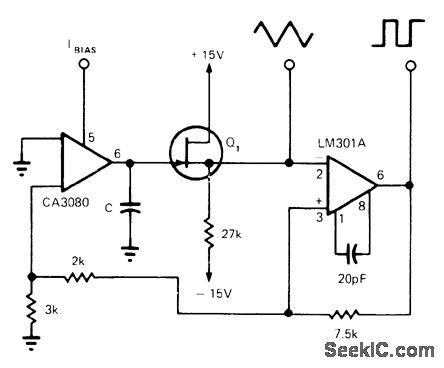
CA3080 oparnp is connected as current-controlled integrator of both polarities for use in current-controlled triangle oscillator.Frequency depends on values of C and opamp bias current and can be anywhere in audio range of 20 Hz to 20 kHz. Square-wave output is obtained by using LM301A opamp as Schmitt trigger.-S. Franco, Current-Controlled Triangular/Square-Wave Generator, EDN Magazine, Sept. 5, 1973, p 91. (View)
View full Circuit Diagram | Comments | Reading(1984)
PROGRAMMABLE_MULTI_TONE_TELEPHONE_RINGER
Published:2009/7/6 20:53:00 Author:May
View full Circuit Diagram | Comments | Reading(803)
3_W_CLASS_AB
Published:2009/7/22 1:27:00 Author:Jessie
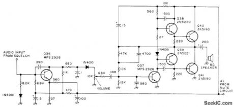
Used in all-band double-conversion super heterodyne receiver for AM, narrow-band FM, CW, and SSB operation. When only noise is present, first audio transistor Q36 is biased out of conduction by squelch and mutes loudspeaker. Supply is 13.6 V regulated. Article gives all circuits of receiver-D. M. Eisenberg, Build This All-Band VHF Receiver, 73 Magazine, Jan, 1975, p 105-112. (View)
View full Circuit Diagram | Comments | Reading(3820)
POWER_LINE_MODEM
Published:2009/7/6 20:52:00 Author:May
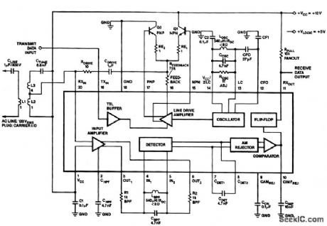
In the 100-kHz application from left to right, the coupling network feeds into the receiver section on the bottom of the chip. (The external components are summarized later.) The receive data output is pulled up via RPULL=10 K Ω. A minimum current of 10 mA sets the voltage drop across RPULL. Another voltage supply, VLOGIC, is shown if the user wants to have the output sent at TTL levels. Across the top is the transmitter section; going from right to left, the oscillator network, the class AB output stage (note feedback resistor RFEEDBACK) and the drive section. The LC values on the oscillator network should match those on the bandpass filter in the receiver. The drive stage feeds into the coupling network and back into the receive section. This enables the on-chip collision detection with listen-while-talking capability. This effect can be canceled, although the transmitter will still be connected to the receiver. (View)
View full Circuit Diagram | Comments | Reading(1121)
TV_AS_DISPLAY_TERMINAL
Published:2009/7/6 20:52:00 Author:May
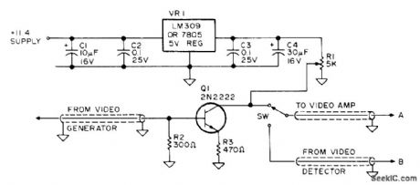
Simple switch inserted in ordinary TV receiver serves for feeding video output of microprocessor directly into video amplifier of set, to give low-cost display terminal. TV must have transformer-type power supply. Excellent set for monitor use is 12-inch Hitachi model P-04, having Hitachi SX chassis. This set has very wide bandwidth, giving sharp display with line widths up to 80 characters.-G. Runyan, The Great TV to CRT Monitor Conversion, Kilobaud, July 1977, p 30-31 (View)
View full Circuit Diagram | Comments | Reading(697)
FULL_WAVE_DRIVE_FOR_D_C_MOTOR
Published:2009/7/22 1:26:00 Author:Jessie
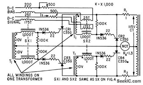
Requires four controlled rectifiers and centertapped transformer. Four magnetic cores ate required for full-wave push-pull action.-W. R. Seegmiller, Controlled Rectifiers Drive A.C and D.C Motors, Electronics, 32:46, p 73-75. (View)
View full Circuit Diagram | Comments | Reading(678)
1000;1_FREQUENCY_SWEEP_
Published:2009/7/6 20:51:00 Author:May
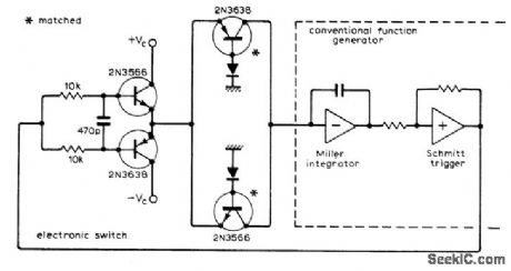
Permits varying output frequency of function generator over wide trequency range by using pot to vary control voltage Vc. Network consisting of two transistors and two diodes replaces usual charging resistor of Miller integrator in function generator, and has output cunent varying exponentially with input voltage. Electronic switch using pair of transistors is controlled by Schmitt trigger of function generator, which connects +Vc and -Vc altemately to charging circuit. If frequency pot is mechanically connected to strip-chart recorder, Bode plots of audio equipment can be made over entire audio range.-P.D. Hiscocks, Function Generator Mod. for Wide Sweep Range, Wireless World, Aug. 1973, p 374. (View)
View full Circuit Diagram | Comments | Reading(733)
GONIOMETER_MOTOR_AMPUFIER
Published:2009/7/22 1:24:00 Author:Jessie
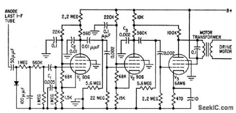
Portion of adf receiver output is separately rectified and applied to selective amplifier V1.V2-V3.C1, C2, and C3 develop 90° phase shift re quired between two coils of goniometer drive motor and serve also as low-pass fiber with sharp cutoff above 150 cps. Overall gain is high enough so motor will exert full torque when goniometer is only 3° off true null.-J. r. Hatch and D. W. G. Byatt, Direction Finder with Automatic Readout Electronics, 32:16, p 62-64. (View)
View full Circuit Diagram | Comments | Reading(1203)
DIGITAL_CTCSS_OSCILLATOR
Published:2009/7/22 1:24:00 Author:Jessie
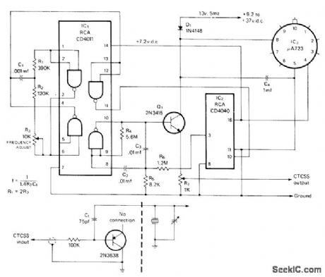
Uses two gates of CM0S quad NAND gate as 3.2-kHz oscillator, one gate as buffer, and one as amplifier serving in active bandpass filter. Requires only one precision capacitor, and uses ordinary carbon resistors in frequency-determining network. C1 must be polystyrene, polycarbonate, Teflon, or silver mica. IC2 divides oscillator frequency by binary multiple. Output is fed back to gate of IC, for convening square wave into sine wave by filtering out high-frequency harmonics. Provides continuous- tone-coded subaudible squelch (CTCSS) for amateur repeater system to protect input from interference on commonly shared channels, Voltage regulator can be replaced by zener. Use base-collector junction of 2N3638 or equivalent transistor as varactor in parallel with transmitter crystal of true FM transmitter, to modulate output frequency of crystal oscillator for CTCSS encoding.-D. Dauben, Miniature Solid State Tone Encoders to Replace Reeds, CQ, Dec, 1975, p 42-45 and 76. (View)
View full Circuit Diagram | Comments | Reading(644)
EIGHT_TONE_CRANE_MOTOR_CONTROL
Published:2009/7/22 1:23:00 Author:Jessie
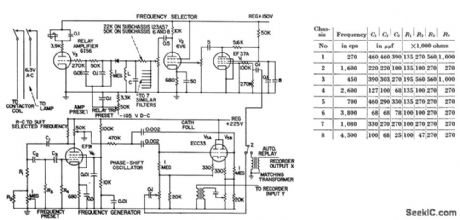
Eight preset frequencies or tones activate collector relays that operate crane motor contactors. Sequence of preselected operations, recorded on magnetic tape, is repeated by traveling crane during playback, to give positioning accuracies better than 1/8th inch. Table gives values of R-C network compo nents in grid circuit of phase-shift oscillator to provide the eight tones.-G. V. Sadler, Taped Tones Control Overhead Crane, Electronics, 31:1, p 63-65. (View)
View full Circuit Diagram | Comments | Reading(3289)
CONSTANT_MOTOR_SPEED
Published:2009/7/22 1:21:00 Author:Jessie
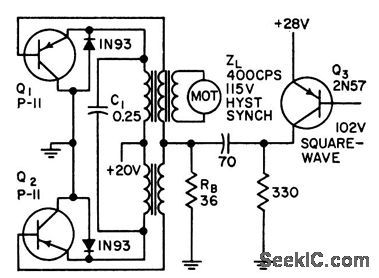
Precise control of instantaneous voltage and current for power transistors gives 90% operating efficiency in driving 400-cps synchronous motor of portable lope transport from 28 v d-c. Negative 800-cps synchronizing pulses from precision oscillator are applied to base of Q3 to pro duce positive pulses at bases of Q1 and Q2, cutting them off quickly.-J. W. Caldwell and T. C. G. Wagner, Boosting Power Transistor Efficiency, Electronics, 31:47, p 86-88. (View)
View full Circuit Diagram | Comments | Reading(689)
AUDIO_SQUELCH
Published:2009/7/22 1:21:00 Author:Jessie
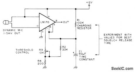
Used to suppress back-ground noise during intervals between sentences and words when operating amateur radio station on VOX and using compressor. Circuit attenuates audio path below preset input level determined by setting of R3.-Circuits, 73 Magazine, May 1977, p 19. (View)
View full Circuit Diagram | Comments | Reading(2289)
FULL_WAVE_CONTROL
Published:2009/7/22 1:20:00 Author:Jessie
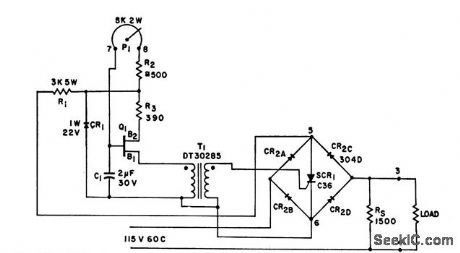
Uses only one control rectifier and one single-ended trigger to obtain continuously variable ac or d-c full-wave output. May be designed for any standard service power voltage. Trigger is always synchronized with power bridge be-cause both obtain power from same source Used to drive and adjust speed of single-phase induction motor, drive and adjust speed of universal motors in machine tools, and vary light output of high-power incandescent lamp.-Full-Wave Control with One Trigger and One Control Rectifier, Electronic Circuit Design Handbook, Mactier Pub Corp., N.Y., 1965, p 187. (View)
View full Circuit Diagram | Comments | Reading(1)
CARRIER_OPERATED_SWITCH
Published:2009/7/22 1:19:00 Author:Jessie
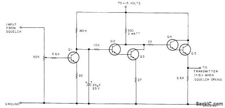
Turns on transmitter of 2-meter FM transceiver (used as repeater) when squelch of receiver is broken by signal. Transmitter remains on about 1s after received signal disappears; for longer delay, use larger electrolytic on collector of Q1. Q1-Q4 can be 2N3904, 2N3565, 2N2222, or other good NPN switching transistor. Q5 is 2N3054 or equivalent, capable of handling 25V at 1 A.-H Cone, The Minirepeater,73 Magazine, June 1975,p55-57,60-62,and 64-65. (View)
View full Circuit Diagram | Comments | Reading(1255)
| Pages:1018/2234 At 2010011002100310041005100610071008100910101011101210131014101510161017101810191020Under 20 |
Circuit Categories
power supply circuit
Amplifier Circuit
Basic Circuit
LED and Light Circuit
Sensor Circuit
Signal Processing
Electrical Equipment Circuit
Control Circuit
Remote Control Circuit
A/D-D/A Converter Circuit
Audio Circuit
Measuring and Test Circuit
Communication Circuit
Computer-Related Circuit
555 Circuit
Automotive Circuit
Repairing Circuit