
Circuit Diagram
Index 1010
Basic_triac_control_circuit_that_uses_an_SBS
Published:2009/7/21 23:04:00 Author:Jessie
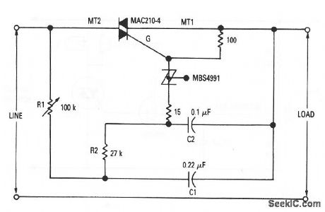
This figure shows the basic control circuit for triacs that use SBS triggers. The line voltage and load current depend primarily on the triac characteristics. In this case, the MAC210-4 accommodates loads up to 10 A. (View)
View full Circuit Diagram | Comments | Reading(1236)
Electronic_crowbar
Published:2009/7/21 23:02:00 Author:Jessie
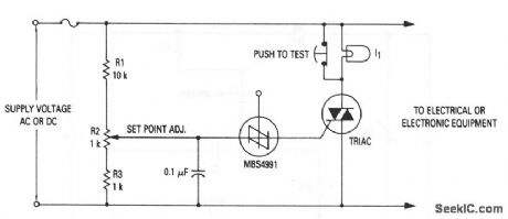
This circuit provides positive protection of expensive electrical or electronic equipment against excessive supply voltage (resulting from improper switching, short circuits, failure of regulators, etc.). The circuit is used where it is economically desirable to shut down equipment, rather than allow the equipment to operate at excessive voltages. The circuit quickly places a short across the power lines (ac or dc), and thereby drops the voltage to the protected device to near zero and blows a fuse. With the values shown, the crowbar operating point (set point) can be adjusted over the range of 60 to 120 Vdc or 42 to 84 Vac. The values of R1 to R3 can be changed to cover different supply voltages, but the triac voltage rating must be greater than the highest operating point that is set by R2. Lamp II (with a voltage rating that is equal to the supply) can be used to check the set point and operation of the circuit, by opening the push-to-test switch and adjusting the input or set point to fire the SBS. An alarm unit such as the Mallory Sonalert can be connected across the fuse to provide an audible indication of crowbar action. Notice that this circuit cannot act on short, infrequent power-line transients. (View)
View full Circuit Diagram | Comments | Reading(0)
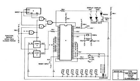
40_MHz_frequency_and_period_counter
Published:2009/7/21 23:02:00 Author:Jessie

40 MHz frequency and period counter. To obtain the frequency and period it is necessary to divide the 10 MHz oscillator frequency down to 2.5 MHz. In doing this the time between measurements is 800 ms and the display multiplex rate is 125 hertz (courtesy Intersil, Inc.). (View)
View full Circuit Diagram | Comments | Reading(1762)
PORTABLE_TOY_SIREN
Published:2009/7/22 1:09:00 Author:Jessie
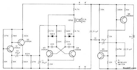
Can be assembled in small box as toy for small child. If mercury switch is used for S1, siren comes on automatically when box is picked up. MVBR Q1-Q2 controls rate at which siren wails, while Q3 and Q4 form AF MVBR that produces actual siren sound with frequency varied by triangle waveform on C1. MVBR Q5-Q6 is mono that conducts for preset time period when S1 is dosed, for applying power to siren. Values shown give 12 s of operation before siren is shut off. When carried by child, siren is jostled enough so it keeps recycling.-J. H. Everhart, Super Siren, 73 Magazine, Feb. 1978, p 96-97. (View)
View full Circuit Diagram | Comments | Reading(1004)
VARIABLE_PLATE_RESISTANCE_MODULATOR
Published:2009/7/22 1:08:00 Author:Jessie
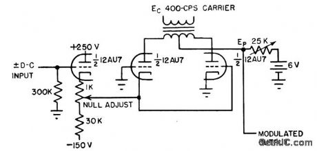
Increasing magnitude of carrier voltage in-creases modulated output. Used in amplification of d-c signals for automatic control systems.-L. S. Klivans, Modulators for Automatic Control Systems, Electronics, 31:1, p 82-84. (View)
View full Circuit Diagram | Comments | Reading(964)
RING_MODULATOR
Published:2009/7/22 1:08:00 Author:Jessie
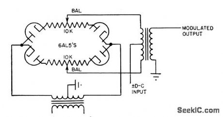
Can be operated with either input or output ungrounded. With 100-v rms carrier and d-c input of 30 v, output is linear up to 0.2 v rms. Null level is less than 1 mv, but drift stability is poor and balance is critical. Used in applications where modulation of error signal is re quired.-L. S. Klivans, Modulators for Automatic Control Systems, Electronics, 31:1, p 82-84. (View)
View full Circuit Diagram | Comments | Reading(819)
4_W_LINEAR
Published:2009/7/6 23:46:00 Author:May

Produces power output of 4 W across high-frequency BF range from 300 kHz to 30 MHz, for output of low-power ORP transmit-ter or as driver for final amplifier of higher-power transmitter. Gain is only 3 dB down at frequency limits and is still useful at 6 meters.Amplifier output may be shorted or left open ;n-definitely even with full drive. Stability and wide frequency response are achieved by add-ing considerable negative feedback to other-wise conventional broadband amplifier, In and T2 are wound on two-hole balun cores as found in TV sets, such as Phillips 4322-020-31520. Two lengths of No. 22 enamel are twisted about 3 times per inch and then wound through cote as shown. One end of one wire is connected to op-posite end of other wire to serve as center tap for transformer. Transformers are responsible for widefrequency response of amplifier.-J. A.Koehler, Four-Watt Wideband Linear Amplifier, Ham Radio, Jan. 1976, p 42-44. (View)
View full Circuit Diagram | Comments | Reading(1591)
LOUD_BIKE_SIREN
Published:2009/7/22 0:01:00 Author:Jessie

Uses 5558 dual opamp and four general-purpose NPN transistors to generate triangle wave that can be distorted by 10k symmetry control to give either fast or slow rise for sawtooth applied as base bias to astable MVBR Q1-Q2. Drain is reasonably low with 9-V radio battery, Repetition rate can be varied from long wail to rapid warble, and volume changed from soft to annoying. Article gives construction details, and recommends use of removable mounting on bike to avoid theft.-R. Megirian, Simple Electronic Siren, 73 Magazine, Oct.1977.p176-177. (View)
View full Circuit Diagram | Comments | Reading(913)
144_MHz_LOW_POWER
Published:2009/7/6 23:44:00 Author:May
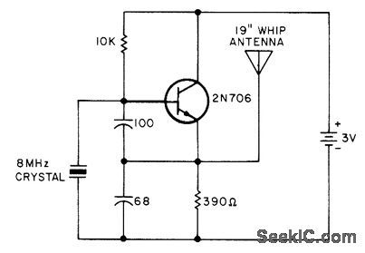
Used as weak-signal source for tuning circuits of 2-m receiver or preamp when no stations are on air.-C. Sond-geroth, Really Soup Up Your 2m Receiver, 73 Magazine, Feb. 1976, p 40-42. (View)
View full Circuit Diagram | Comments | Reading(769)
FOUR_QUADRANT_MULTIPLIER
Published:2009/7/6 23:43:00 Author:May
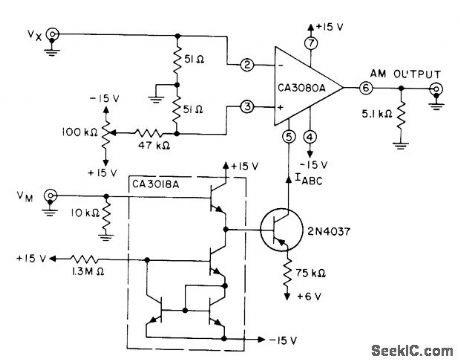
Provides amplitude modulation for applications where low power consumption is more important than accuracy. Uses CA3080A variable opamp in combination with transistors of CA3018A array and 2N4037 amplifier for bias current of opamp. Ac-curacy is within 7% full scale.- Circuit Ideas for RCA Linear ICs, RCA Solid State Division, Somerville, NJ, 1977, p 15. (View)
View full Circuit Diagram | Comments | Reading(2005)
VARIABLE_TONE_USING_VCO
Published:2009/7/22 Author:Jessie
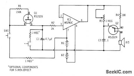
Tone generator uses UJT and opamp in voltage-controlled oscillator Frequency of audio output is determined by setting of R3 For two-tone siren effects, optioal switches and resistors can be used, To speed up siren effect, use smaller value for C1.-F.M Mims, Integrated Circuit Projects,vol.4, Radio Shack, Fort Worth,TX,1977,2nd Ed.p61-69. (View)
View full Circuit Diagram | Comments | Reading(918)
SQUARE_TRIANGLE_VCO
Published:2009/7/6 23:42:00 Author:May
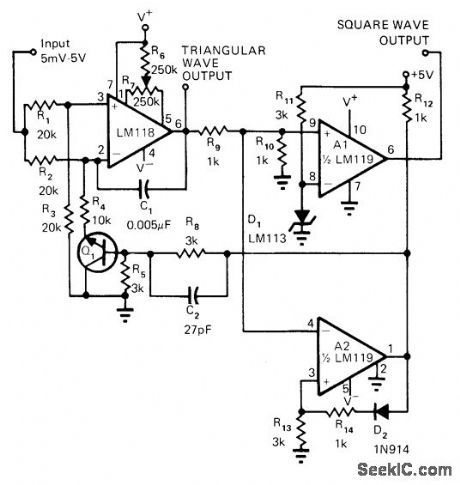
With DC control voltage of 5 mV to 5 V, circuit controls frequency of both square and triangle outputs with good linearity. Peak value of triangle output is precisely set at 2.44 V and 0 V by reference voltages at noninverting inputs of comparators.Comparator A2 drives load for low outputs, while comparator A1 drives load when output is high. Article tells how circuit works.-R. C.Dobkin, Comparators Can Do More Than Just Compare, EDN Magazine, Nov. 1, 1972, p 34-37. (View)
View full Circuit Diagram | Comments | Reading(1177)
Precision_frequency_counter_tachometer
Published:2009/7/21 23:59:00 Author:Jessie

Precision frequency counter/tachometer. The ICM7207A provides a 1-second gating window and the store and reset signals. The display reads hertz directly. With pin 11 of the ICM7207A connected to V+ the gating time will be 0. 1 second, which gives tens of hertz in the LSB position. For shorter gating times a 6.5536 MHz crystal may be used, giving a 0.01-second gating with pin 11 connected to V+ and a 0.1-second gating with pin 11 open. To implement the 4-digit tachometer the ICM7207A with a 1-second gating should be used. In order to get the display to read directly in RPM the rotational frequency must be multiplied by 60.This can be done electronically using a PLL or mechanically using a disc rotating with the object with appropriate hole drilled for light from an LED to a photodevice (courtesy Intersil, Inc.). (View)
View full Circuit Diagram | Comments | Reading(0)
WHOOPER
Published:2009/7/21 23:59:00 Author:Jessie
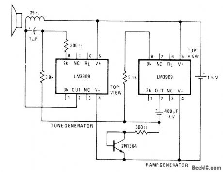
Two National LM3909 ICs and single transistor generate rapidly modulated tone resembling that used on some police cars, ambulances, and airport emergency vehicles. Rapidly rising and falling modulating voltage is generated by IC having 400-μF capacitor. Diode-connected transistor forces this IC ramp generator to have ranger ON periods than OFF periods, raising average tone of tone generator and making modulations seem more even.- Linear Applications, Vol. 2, National Semiconductor, Santa Clara, CA, 1976, AN-154, p 7. (View)
View full Circuit Diagram | Comments | Reading(0)
5_W_FET_TRANSMITTER
Published:2009/7/6 23:41:00 Author:May
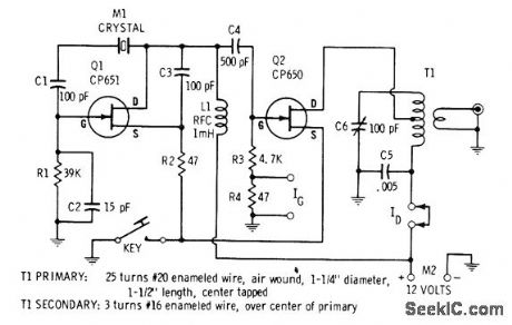
Vaiues shown give operation in 40-meter amateur band. Drain of resonant tank circuit.-E. M. Noll, FET Principles, Experiments, and Projects, Howard W.Sams, Indianapolis, IN, 2nd Ed., 1975, p 188-power FET Q2 is connected to tap on primary of 189. (View)
View full Circuit Diagram | Comments | Reading(1224)
PDM_WITH_CLOCK
Published:2009/7/6 23:40:00 Author:May
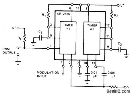
First section of Exar XR-2556 dual timer operates as pulse-duration modulator and second section as clock generator, eliminating need for external clock, Supply voltage is 4.5-16V. Values of R and C determine frequency and pulse duration of output.- Timer Data Book, Exar Integrated Systems, Sunnyvale, CA, 1978, p 23-30. (View)
View full Circuit Diagram | Comments | Reading(711)
Thermocouple_temperature_control
Published:2009/7/21 23:36:00 Author:Jessie
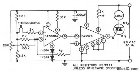
This circuit shows a CA3080A OTA (chapter 11) and a CA3079 zero-voltage switch that are connected to form a thermocouple temperature control, where the CA3079 functions as an output amplifier. (View)
View full Circuit Diagram | Comments | Reading(4038)
100_MHz_frequency_counter_using_the_Intersil_ICM7216C_28_pin_DIP
Published:2009/7/21 23:33:00 Author:Jessie

100 MHz frequency counter using the Intersil ICM7216C 28-pin DIP (courtesy Intersil, Inc.). (View)
View full Circuit Diagram | Comments | Reading(2965)
Line_operated_IC_timer_for_Long_time_periods
Published:2009/7/21 23:33:00 Author:Jessie
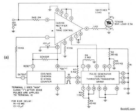
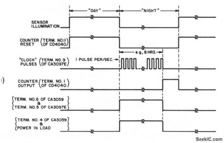
This circuit provides tum-on to a 2.5-A load after a long time period. The delay is set by the values of R1 and C1, as shown by the equations. The timing diagram is shown in Fig. 8-32B. (View)
View full Circuit Diagram | Comments | Reading(844)
100_MHz_frequency_and_period_counter_using_the_Intersil_ICM7226B_40_pin_DIP
Published:2009/7/21 23:31:00 Author:Jessie
100 MHz frequency and period counter using the Intersil ICM7226B 40-pin DIP. This circuit uses a CD4016 analog multiplexor to multiplex the digital outputs back to the function input. Since the CD4016 is a digitally controlled analog transmission gate no level shifting of the digital output is required. CD4051s or CD4052s could also be used to select the proper inputs for the multiplexed input on the ICM7226 from 2-or 3-bit digital inputs. These analog multiplexers could also be used in systems in which the mode of operation is controlled by a microprocessor rather than directly by front panel switches (courtesy Intersil, Inc.). (View)
View full Circuit Diagram | Comments | Reading(2664)
| Pages:1010/2234 At 2010011002100310041005100610071008100910101011101210131014101510161017101810191020Under 20 |
Circuit Categories
power supply circuit
Amplifier Circuit
Basic Circuit
LED and Light Circuit
Sensor Circuit
Signal Processing
Electrical Equipment Circuit
Control Circuit
Remote Control Circuit
A/D-D/A Converter Circuit
Audio Circuit
Measuring and Test Circuit
Communication Circuit
Computer-Related Circuit
555 Circuit
Automotive Circuit
Repairing Circuit