
Circuit Diagram
Index 1014
SINGLE_SUPPLY_AM
Published:2009/7/6 22:04:00 Author:May
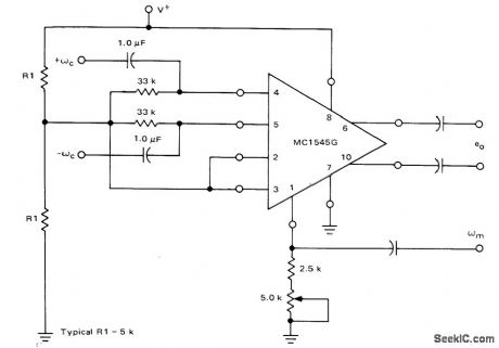
Motorola MC1545 gated video amplifier is connected as amplitude modulator operating from single supply. Artificial ground is established for IC at half of supply voltage by 5K resistors R1, which should draw much more than bias current of 15μA. All signals must be AC coupled to prevent application of excessive common-mode voltage to IC.- Gated Video Amplifier Applications-the MC1545, Motorola, Phoenix, AZ, 1976, AN-491, p 15. (View)
View full Circuit Diagram | Comments | Reading(717)
NONLINEAR_CUBIC_AND_QUADRATIC
Published:2009/7/6 22:04:00 Author:May
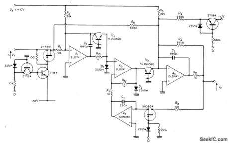
Provides four-quadrant operation with high accuracy over input amplitude range of several decades. Applications include analog computations for radar and ballistic problems,linearization of transducer characteristics, and teaching theory of quadratic equations. Article gives design equations and complete design produce.-H.Mcpherson,Non-Linear Function Generator,Wirelessworld,Oct.1972,p485-487. (View)
View full Circuit Diagram | Comments | Reading(878)
FIRE_SIREN_USES_FLASHER
Published:2009/7/21 23:21:00 Author:Jessie
Low-drain circuit operating from 1.5-V cell uses National LM3909 flasher IC to simulate fire-alarm siren. Pressing button produces rapidly rising wail, with tone coasting down in frequency after button is released. Sound from loudspeaker resembles that of motor-driven siren. Volume is adequate for child's pedal car.-P. Lefferts, Power-Miser Flasher IC Has Many Novel Applications, EDN Magazine, March 20, 1976, p 59-66. (View)
View full Circuit Diagram | Comments | Reading(1069)
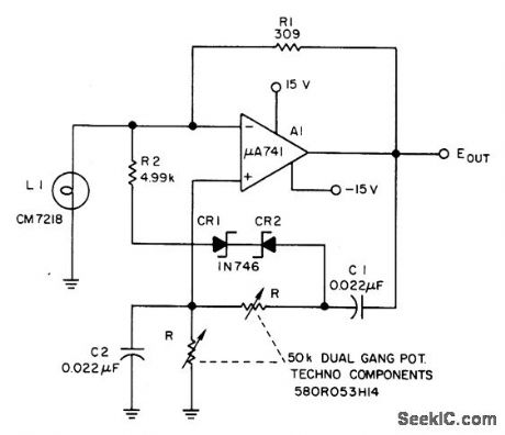
ADJUSTABLE_SINE_WAVE_AUDIO_OSCILLATOR
Published:2009/7/6 22:01:00 Author:May
Circuit Notes
Waveform purity at low frequencies for a Wien bridge oscillator is enhanced by diode limiting. Lamp L1 stabilizes the loop gain at higher frequencies while the limiting action of R2, CR1, and CR2 prevents clipping at low frequencies and increases the frequency adjustment range from about 3:1 to greater than 10:1. (View)
View full Circuit Diagram | Comments | Reading(713)
Line_operated_one_shot_timer
Published:2009/7/21 23:21:00 Author:Jessie
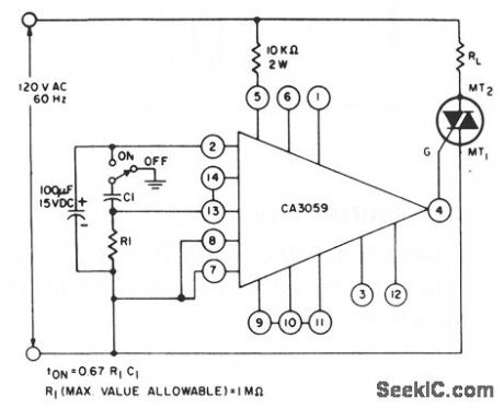
This circuit uses a CA3059 zero-voltage switch to control triac operation. The turn-on time of the triac (and thus the current through load RL) is set by the values ofR and C, as shown by the equations. (View)
View full Circuit Diagram | Comments | Reading(1981)
SIREN
Published:2009/7/21 23:20:00 Author:Jessie
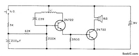
Creates sounds resembling those of police-car siren in which air is forced through slots in motor-driven disk. L1 is half of audio transformer, using winding having 10K center tap.-Circuits, 73 Magazine, April 1977, p 164. (View)
View full Circuit Diagram | Comments | Reading(2)
PULSE_RATIO_MODULATOR
Published:2009/7/6 22:01:00 Author:May
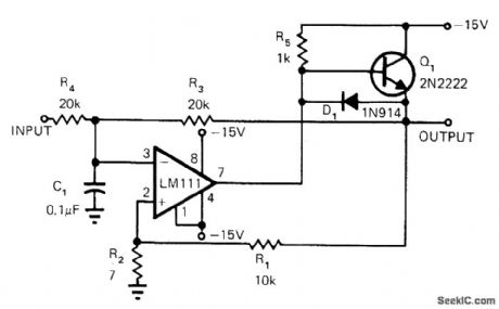
LM111 comparator serves with single transistor to provide pulse-train output whose average value is proportional to input voltage. Frequency of output is relatively constant but pulse width varies .Pulse-ratio accuracy is 0.1%. Circuit can be used to drive power stage of high-efficiency switching amplifier, or as pulse-width/pulse-height multiplier. Article tells how circuit works.-R.C. Dobkin, Comparators Can Do More than Just Compare, EDN Magazine, Nov. 1, 1972, p34-37. (View)
View full Circuit Diagram | Comments | Reading(1007)
WIEN_BRIDGE_OSCILLATOR_USES_CMOS_CHIP
Published:2009/7/6 21:59:00 Author:May
View full Circuit Diagram | Comments | Reading(737)
40_MHz_frequency_counter_using_the_Intersil_ICM7216C_28_pin_DIP
Published:2009/7/21 23:19:00 Author:Jessie
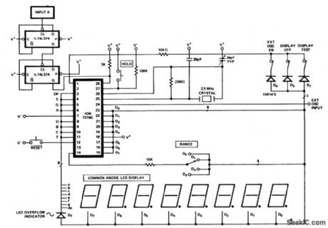
40 MHz frequency counter using the Intersil ICM7216C 28-pin DIP. To measure the correct value the 2.5 MHz oscillator frequency is divided by four as well as the input frequency (courtesy Intersil, Inc.). (View)
View full Circuit Diagram | Comments | Reading(2007)
Relay_contact_protection_that_uses_a_triac
Published:2009/7/21 23:19:00 Author:Jessie
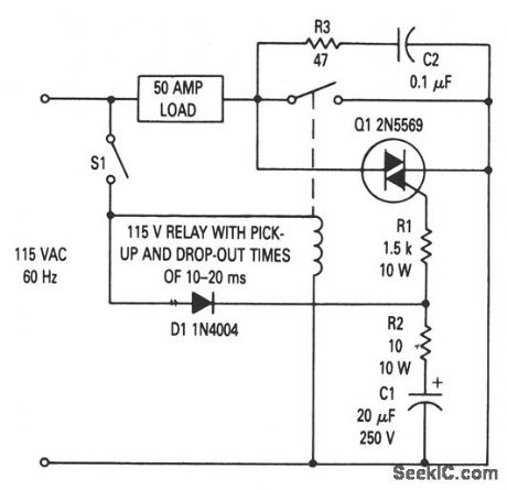
This circuit prevents relay-contact arcing for loads up to 50 A (many 5-A relays can be used for a 50-A load with this circuit). Using the values shown, triac Q1 turns on before the relay closes (when S1 is closed) and remains on after the relay opens. This minimizes arcing (and contact bounce ), even though the load current passes through the relay contacts. R3 and C1 act as a snubber to reduce dv/dt, if any other switching element is used on the line (and thus prevents Q1 from being turned on by transients). (View)
View full Circuit Diagram | Comments | Reading(1416)
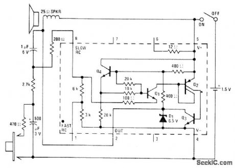
LOW_NOTE_SIREN
Published:2009/7/21 23:18:00 Author:Jessie
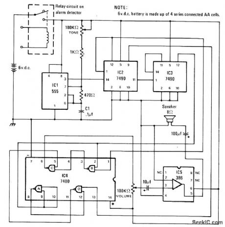
Produces up/down blooping sounds characteristic of European police cars and now being used on some US emergency vehicles. Can be connected to burglar or theft alarm system for protection purposes, or used as portable sound box operated by momentary pushbutton switch. Includes volume control and tone control that varies both pitch and rate.-D. Heiserman, Whizbox, Modern Electronics, June 1978, p 67. (View)
View full Circuit Diagram | Comments | Reading(664)
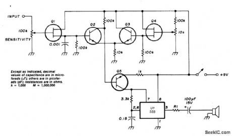
A_555_USED_AS_AN_RC_AUDIO_OSCILLATOR
Published:2009/7/6 21:57:00 Author:May


Circuit Notes
Transistor Q5 and the 1000 ohm resistor form the variable element needed for controlling the frequency of VDO by limiting the charging current flowing into the 0.15μF timing capacitor according to the forward bias being applied to Q5. As the voltage on pins 2 and 6 of U1 reach 2/3 VCC (about 6 volts with a 9-volt supply) the timer will fire and pin 3 will be pulled low. Pin 7, an open collector output, goes low and begins to discharge the timing capacitor-through the 3.3 kilohm resistor. The discharge time provided by this resistor assures a reasonable, although asymmetrical, waveform for the aural signal generated by U1. At 1/3 VCC the intemal flip-flop resets, the output on pin 3 goes high, the open collector output on pin 7 floats, and the timing cycle begins again. (View)
View full Circuit Diagram | Comments | Reading(1039)
Multiplexed_BCD_to_7_segment_decoder_driver_displays_for_a_24_hour_clock
Published:2009/7/21 23:18:00 Author:Jessie
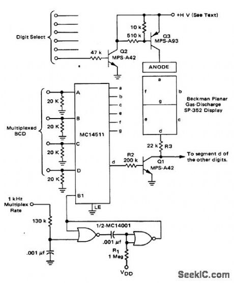
Multiplexed BCD-to-7-segment decoder/driver/displays for a 24-hour clock. Supply voltage of 160 to 200 volts is required to power the display (courtesy Motorola Semiconductor Products Inc.). (View)
View full Circuit Diagram | Comments | Reading(1525)
1MHz
Published:2009/7/6 21:57:00 Author:May
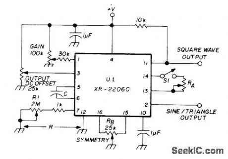
Simple sinusoidal generator using Exar XR-22060 IC provides sine, triangle, or square outputs. For sine output, S1 is closed and RA and RB are adjusted tor minimum distortion. Exact output frequency f is 1/RC where R is about 2 megohms from pin 7 to ground and C is connected between pins 5 and 6. FM output is obtained when modulating input is applied to either pin 7 or 8. For AM output, modulation is applied to pin 1.-E. Noll, VHF/UHF Single-Frequency Conversion, Ham Radio, April 1975, p 62-67. (View)
View full Circuit Diagram | Comments | Reading(1225)
REDUC_DISTORTION_
Published:2009/7/6 21:54:00 Author:May
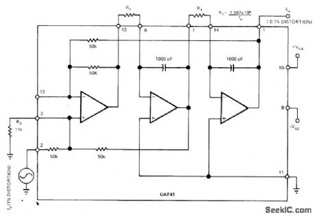
Use of UAF41 universal active filter at output of function generator reduces distortion of sine-wave output by eliminating some of harmonics. In typical application, two-pole active filter reduces 1% distortion down to 0.1%, using low-pass configuration. Articlegives design equations. For 1-kHz cutoff, R1, should be 159.2K.-Y. J. Wong, Design a Low Cost, Low-Distortion, Precision Sine-Wave Oscillator, EDN Magazine, Sept. 20, 1978,p107-113. (View)
View full Circuit Diagram | Comments | Reading(1047)
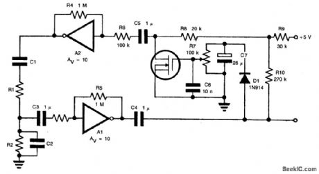
MODIFIED_UJT_RELAXATION_OSCILLATOR_PRODUCES_GLEAN_AUDIO_SINUSOIDS
Published:2009/7/6 21:52:00 Author:May

Circuit NotesBy placing a tuned circuit in the UJT oscillator's current-pulse path, a 3750-Hz sinusoid can be created at B2 with the component values shown. (View)
View full Circuit Diagram | Comments | Reading(932)
LOW_COST_WIEN_BRIDGE_OSCILLATOR
Published:2009/7/6 21:51:00 Author:May
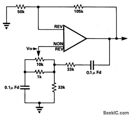

Circuit Notes
In the circuit the frequency trimming component is arranged so that the voltage across it is in quadrature with the voltage V, from the bridge so that as it is adjusted the attenuation of the bridge only changes a little, avoiding the need for a two gang component. The range of variation of frequency is very limited. By using a high gain amplifier and metal film feedback resistors the loop gain can be set so that the unit just oscillates and the use of an automatic gain setting component, a thermistor for example, is eliminated. (View)
View full Circuit Diagram | Comments | Reading(1284)
SINGLE_FREQUENCY_CONTROL
Published:2009/7/6 21:50:00 Author:May
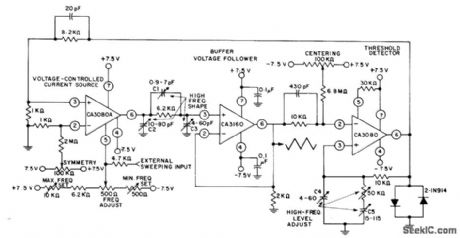
Adjustment range of over 1,ooo,ooo to 1 for frequency is achieved by using CA3080A as programmable current source,CA3160 opamp as voltage follower, and CA3080 variable opamp as high-speed capacitor. Variable capacitors C1-C3 shape triangle waveform between 500 kHz and 1 MHz. C4 and C5 with 50K trimmer in series with C5 maintain constant amplitude within 10% up to1 MHz,-''Circuit Ideas for RCA Linear ICs、″RCA Solid State Division,Somerville,NJ,1977,p 6. (View)
View full Circuit Diagram | Comments | Reading(729)
POLICE_SIREN_USES_FLASHER
Published:2009/7/22 1:07:00 Author:Jessie
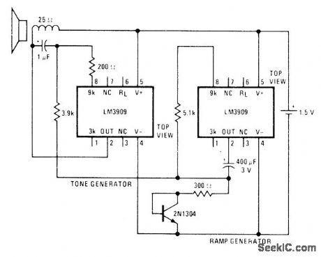
Low-drain circuit operating from 1.5-V cell uses National LM3909 flasher ICs to simulate whooper sounds of electronic sirens used on some city police cars and ambulances. Two flashers are required for generating required rapidly rising and falling modulating voltage. Transistor is connected as diode to force ramp generator of IC to have longer ON periods than OFF periods, raising average tone and making modulation seem more even.-P. Lefferts, Power-Miser Flasher IC Has Many Novel Applications, EDN Magazine, March 20, 1976, p 59-66. (View)
View full Circuit Diagram | Comments | Reading(890)
SIMPLE_AUDIO_SINE_WAVE_GENERATOR
Published:2009/7/6 21:45:00 Author:May
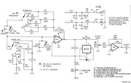
Circuit Notes
U1A, an op amp, oscillates at the frequency at which the phase shift in the Wien bridge network is exactly zero degrees. Changing bridge component values changes the oscillator frequency. In this circuit, we need change only the two resistors to do this. S1A chooses a value among R1 through R6, and S1B similarly selects a value from R7 through R12. U1A must provide enough gain to overcome losses in the bridge, but not so much gain that oscillation builds up to the point of overload and distortion. U2 andC1 automatically regulate circuit gain to maintain oscillation. U2 places D1 across R13 with the proper polarity on both positive and negative alterations of the signal at pin 1 of U1. As the voltage at pin 1 of U1 approaches its peak value, D1 enters its Zener breakdown region, effectively shunting R13 with a resistive load. This increases the amount of negative feedback around U1, reducing its gain. R15, WAVEFORM ADJ, allows you to optimize circuit operation for lowest distortion. U1B provides isolation between oscillator and load. With the values shown for R17 and R18, U1B operates at unity gain. (View)
View full Circuit Diagram | Comments | Reading(1732)
| Pages:1014/2234 At 2010011002100310041005100610071008100910101011101210131014101510161017101810191020Under 20 |
Circuit Categories
power supply circuit
Amplifier Circuit
Basic Circuit
LED and Light Circuit
Sensor Circuit
Signal Processing
Electrical Equipment Circuit
Control Circuit
Remote Control Circuit
A/D-D/A Converter Circuit
Audio Circuit
Measuring and Test Circuit
Communication Circuit
Computer-Related Circuit
555 Circuit
Automotive Circuit
Repairing Circuit