
Circuit Diagram
Index 1003
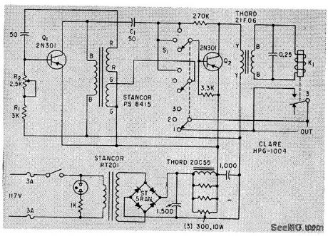
RIFLE
Published:2009/7/7 3:06:00 Author:May
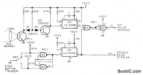
Developed for use with General Instruments AY-3-8500-1 TV game chip to simulate target practice with rifle. Player aims at bright target spot moving randomly across TV screen.If gun is on target when trigger is pulled, phototransistor in barrel picks up light from target and generates pulse for producing sound effect of hit and incrementing player's score. PT-1 can be TIL64 or equivalent phototransistor, 4098 is dual mono, and 4011 is quad two-input NAND gate. Pulse outputs go to pins of game chip.Article gives all circuits but covers construction only in general terms.-S. Ciarcia, Hey, Look What My Daddy Built!, 73 Magazine, Oct. 1976, p 104-108. (View)
View full Circuit Diagram | Comments | Reading(1614)
TRIAC_STARTING_SWITCH_FOR_1_2_hp_MOTOR
Published:2009/7/7 3:04:00 Author:May
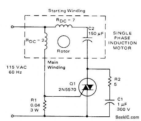
Triac replaces centrifugal switch normally used to control current through starting winding of single-phase induction motor. Value of R1 is chosen so triac turns on only when starting cur-rent exceeds 12A. When motor approaches nor-mal speed, running current drops to 8 A and triac blocks current through starting winding.- Circuit Applications for the Triac, Motorola, Phoenix, AZ, 1971,AN-466, p 8. (View)
View full Circuit Diagram | Comments | Reading(5715)
Ultralong_delay_timer_using_two_8250_16_pin_DIPs
Published:2009/7/21 22:14:00 Author:Jessie
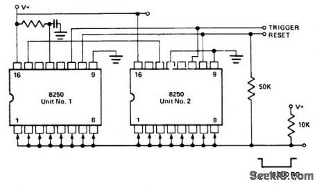
Ultralong delay timer using two 8250 16-pin DIPs. The output is normally high when reset, and goes low upon application of a trigger input. It stays low for a duration of (100)2 or 10,000 cycles. Total timing cycle for the two 8250s can be programmed from TO = 1RC to TO = 9999RC in 10,000 discrete steps by selectively shorting any combination of pins 1 through 8 from both units to the output bus (courtesy Intersil, Inc.). (View)
View full Circuit Diagram | Comments | Reading(681)
THYRISTOR_TRIGGER_PULSE_GENERATOR
Published:2009/7/7 3:02:00 Author:May
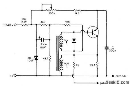
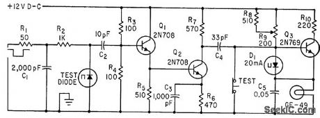
Used with thyristor speed control for 2-hp shunt-wound DC motor. Circuit provides train of pulses with variable delay with respect to zero-crossing instants of AC supply, for feeding to cathode and gate of thyristor to vary duty cycle. Use Mullard BFX29 silicon PNP transistor or equivalent, and any small-signal silicon diode. Output pulses are suitable for triggering all types of thyristors up to largest. Article also gives motor control circuit.-F. Butler, Thyris-tor Control of Shunt-Wound D.C. Motors, Wire-less World, Sept. 1974, p 325-328. (View)
View full Circuit Diagram | Comments | Reading(1958)
Off_on_control_of_a_triac_with_programmable_hysteresis
Published:2009/7/21 22:13:00 Author:Jessie
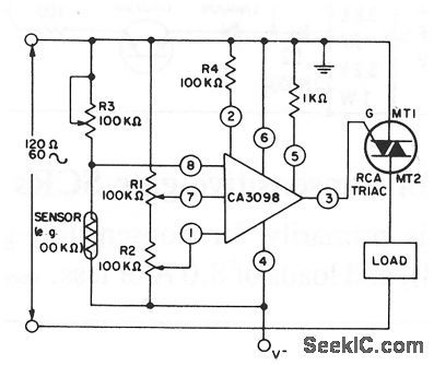
This circuit shows control of a triac with a CA3098 programmable Schmitt trigger. R1 and R7 set the low and high reference voltages, respectively, while R3 sets the control-signal level from the sensor. (View)
View full Circuit Diagram | Comments | Reading(898)
TUNNEL_DIODE_TEST_ATTACHMENT_FOR_CURVE_TRACER
Published:2009/7/21 22:12:00 Author:Jessie
Adapter switches sweep voltages of curve tracer on and off at re duced duty cycle to prevent overheating of tunnel diode while determining its series resistance. Increasing R1 gives lower duty cycle, because R1-R2 control frequency of inductively coupled series-resonance feed-back oscillator Q1.-L. M. Zappulla, Low Duty Cycle Tunnel-Diode Tester, Electronics, 35:4, p 47. (View)
View full Circuit Diagram | Comments | Reading(1757)
Water_level_control
Published:2009/7/21 22:11:00 Author:Jessie
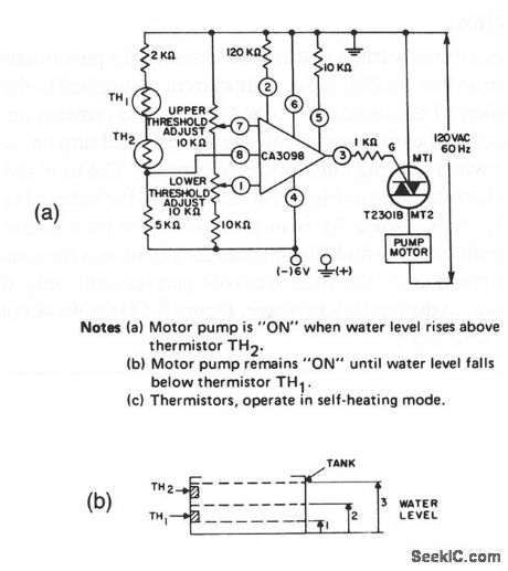
This circuit shows a triac used to provide electronic control of a drain or sump pump. Figure 8-7B shows positioning of the sensor thermistors in the tank that is drained by the pump. The circuit notes explain the operation of the pump Control. (View)
View full Circuit Diagram | Comments | Reading(0)
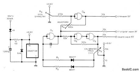
REMOTE_FREQUENCY_CONTROL
Published:2009/7/7 3:00:00 Author:May
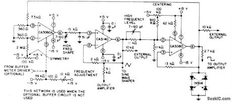
Frequency of square and triangle outputs can be ad justed over range of 1,000,000:1 with 10K pot or by varying DC voltage applied to pin 5 of CA3080A over wire line from remote location. CA3140 serves as noninverting readout amplifier for triangle wave developed across integrating capacitor network at output of CA3080A current source. Second CA3080 acts as high-hysteresis switch having trip level established by four diodes,to give desired square-wave output.-''Linear Integrated Circuits and MOS/FET's,''RCA Solid State Divsion,Somerville,NJ,1977,p 248-254. (View)
View full Circuit Diagram | Comments | Reading(731)
TUNNEL_DIODE_SWITCHING_TIME_TESTER
Published:2009/7/21 22:08:00 Author:Jessie
With values shown, will light only if tunnel diode under test switches within 0.5.nsec.-J. E. Gersbach and I. Lieber, Switching-Time Tester for Tunnel Diodes, Electronics, 35:16, p 48-49. (View)
View full Circuit Diagram | Comments | Reading(856)
REVOLUTION_COUNTING_CONTROL
Published:2009/7/7 2:59:00 Author:May
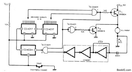
When desired number of revolutions is reached by DC motor, as determined by preset counter, Tr1, is turned off to interrupt path to 5-V motor supply, while TR2 is turned on to brake motor rapidly. Voltage developed across 5-ohm resistor Rs, in series with motor contains frequency component related to speed of rotation and number of armature coils. This signal is amplified by CD4007 CMOS inverter for feeding to counters through signal-squaring inverters. Counter out-puts are decoded by gate 1. Motor slowdown by heavy loads does not affect accuracy of revolution-counting.-R. McGillivray, Motor Revolutions Control, Wireless World, Jan. 1977, p 76. (View)
View full Circuit Diagram | Comments | Reading(1089)
Simple_electronic_control_of_motors
Published:2009/7/21 22:07:00 Author:Jessie
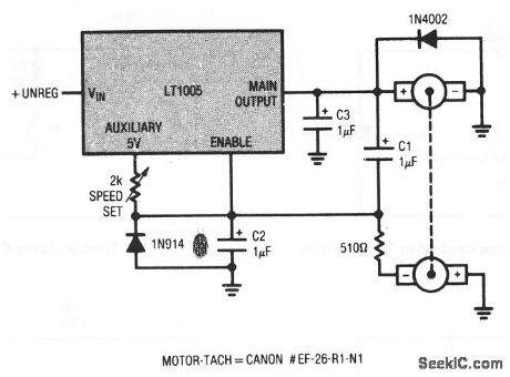
This circuit shows how a simple switch-mode motor controller can be made using an LT1005 multifunction regulator. Motor speed is set by the 2-kΩ pot at the Auxiliary pin of the LT1005. The motor-tach shown has a shaft-torque rating of 20 gram-cMs at 3300 rpm (View)
View full Circuit Diagram | Comments | Reading(795)
PAPER_TAPE_FEED
Published:2009/7/7 2:54:00 Author:May
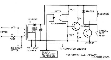
High or 1 bit at output port of microprocessor turns on LED of optocoupler to energize solenoid of pinch-roller drive for paper tape of tape reader. Circuit will control reader from computer keyboard. Optoisolator is essential to keep grounds separate, since mechanical devices are electrically noisy and can generate garbage in computer. Article gives software for tape input routine on 8008 micro-processor.-D. Hogg. The Paper Taper Caper, Kilobaud, March 1977, p 34-40. (View)
View full Circuit Diagram | Comments | Reading(709)
HIGH_PRECISION_TRIANGLE
Published:2009/7/7 2:52:00 Author:May
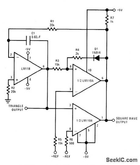
Oρamp circuit provides easily controlled peak-to-peak amplitude of triangle wave suitable for use in sweep clrcuits and test equipment,Positive and negative peak amplitudes are contranable to accuracy of about±0.01 V by DC input Output frequency is likewise easily adjusted overrange of two decades,Circuit consists of integrator and two comparators One comparator sets positive peak,and other sets negative peak Operating frequency depends on R1,C1,and referencevoltages Maximum differencein reference voltagesis 5 V Frequency limit is about 200 kHz.-R .C .Dobkin,''Precise Tri-Wave Generation,″National Semiconductor,Santa Clara,CA,1973,LB-23. (View)
View full Circuit Diagram | Comments | Reading(757)
SHUNT_MODE_SPEED_CONTROL
Published:2009/7/7 2:52:00 Author:May
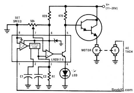
AC tachometer on shaft of DC motor sernves as input for National LM2917N-8 IC acting as shunt-mode regulator with LED indicator. Output of Darling-ton power transistor provides analog drive to motor. As motor speed approaches reference level set by values chosen for R1, C1, and C2, AC current to motor is proportionately reduced so TACH motor comes gradually up to speed and is maintained there without operating in switching mode . Advantage of this arrangement is absence of electric noise normally generated during switching-mode operation.- Linear Applications, Vol. 2, National Semiconductor, Santa Clara, CA, 1976, AN-162 p 10-11. (View)
View full Circuit Diagram | Comments | Reading(3721)
DIGITAL_TEMPERATURE_MEASURING_CIRCUIT
Published:2009/7/7 2:50:00 Author:May
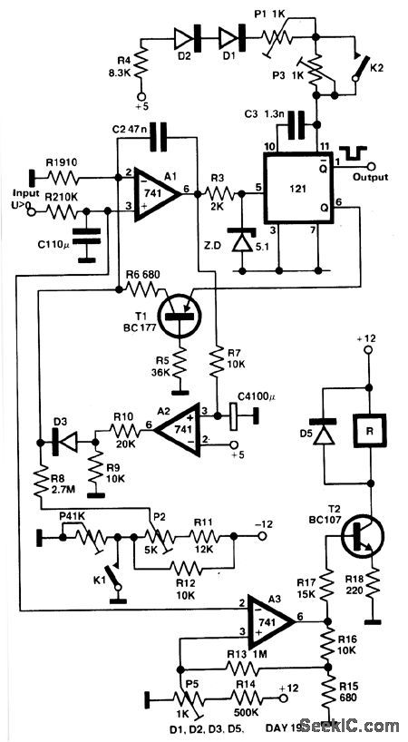
The output voltage of a thermocouple is converted into frequency measured by a digital frequency meter. The measuring set connected with Ni-NiCr thermocouple permits you to measure the temperatures within the range of 5℃ - 800℃ with ±1℃ error. The output thermocouple signal is proportional to the temperature difference between the hot junction and the thermostat kept at 0 ℃, it drives the voltage-to-frequency converter changing the analogue input signal into the output frequency with the conversion ratio adjusted in such a way, that the frequency is equal to the measured temperature in Celsius degrees, e.g., for350℃ the frequency value is 350 Hz. (View)
View full Circuit Diagram | Comments | Reading(1137)
TEMPERATURE_TO_FREQUENCY_CONVERTER
Published:2009/7/7 2:48:00 Author:May
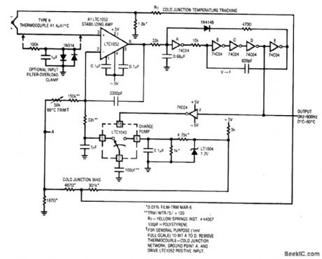
A1's positive input is biased by the thermocouple. A1's output drives a crude V → F converter, comprised of the 74C04 inverters and associated components. Each V→F output pulse cduses a fixed quantity of charge to be dispensed into the 1 μF capacitor from the 100 pF capacitor via the LT1043 switch. The larger capacitor integrates the packets of charge, producing a dc voltage at A1's negative input. A1's output forces the V→F converter to run at whatever frequency is required to balance the amplifier's inputs. This feedback action eliminates drift and nonlinearities in the V→F converter as an error item and the output frequency is solely a function of the dc conditions at A1's inputs. The 3300 pF capacitor forms a dominant response pole at A1, stabilizing the loop. (View)
View full Circuit Diagram | Comments | Reading(3979)
_HI_LO_TEMPERATURE_SENSOR
Published:2009/7/7 2:45:00 Author:May
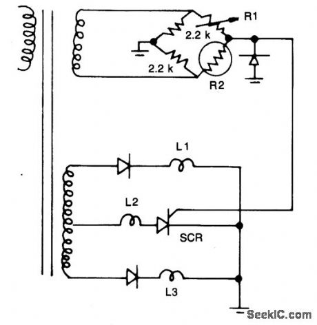
Resistors R1, R2, and the two 2.2 k resistors form a bridge circuit. R2 is a therrnistor, and RI sets the temperature at which L2 lights. Lower or higher temperatures light L1 or L3 to indicate an over- or under-temperature condition. (View)
View full Circuit Diagram | Comments | Reading(1025)
SSB_CW_DEMODULATOR
Published:2009/7/21 22:26:00 Author:Jessie
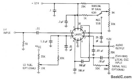
LM373 communication IC uses balanced mixer as product detector, with reinserted carrier reapplied to pin 6. CW or SSB output is taken from pin 7. If desired, RF gain control can be inserted in AGC feedback path.-E. M. Noll, Linear IC Principles, Experiments, and Projects, Howard W. Sams, Indianapolis, IN, 1974, p 350-351. (View)
View full Circuit Diagram | Comments | Reading(2837)
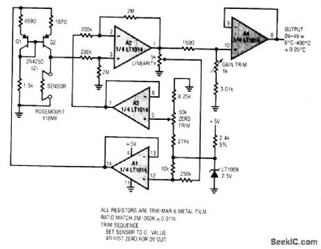
5_V_POWERED,LINEARIZED_PLATINUM_RTD_SIGNAL_CONDITIONER
Published:2009/7/7 2:44:00 Author:May
View full Circuit Diagram | Comments | Reading(572)
NEGATIVE_LOGIC_LAMP_DRIVER
Published:2009/7/21 22:25:00 Author:Jessie
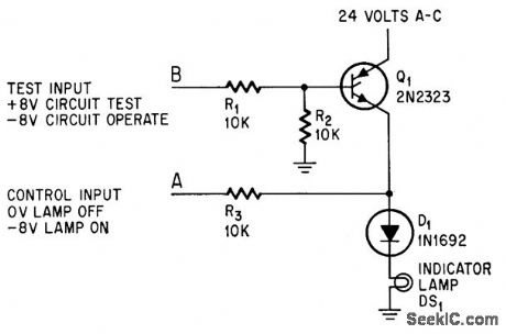
Uses one scr and only five components per lamp, to switch lamps rapidly, without relays or ex costive loading of control source. Positive test signal at B checks circuit and lamp, Control signal (-8 v) forward-biases gate electrode and scr fires during positive ac halfcycles.-A. E, Popodi, Reliable Repertoire Of Display Circuits, Electronics, 38:2, p 60-66. (View)
View full Circuit Diagram | Comments | Reading(811)
| Pages:1003/2234 At 2010011002100310041005100610071008100910101011101210131014101510161017101810191020Under 20 |
Circuit Categories
power supply circuit
Amplifier Circuit
Basic Circuit
LED and Light Circuit
Sensor Circuit
Signal Processing
Electrical Equipment Circuit
Control Circuit
Remote Control Circuit
A/D-D/A Converter Circuit
Audio Circuit
Measuring and Test Circuit
Communication Circuit
Computer-Related Circuit
555 Circuit
Automotive Circuit
Repairing Circuit