
Circuit Diagram
Index 1006
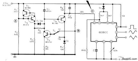
CASSETTE_DRIVE_CONTROLLER
Published:2009/7/7 2:08:00 Author:May
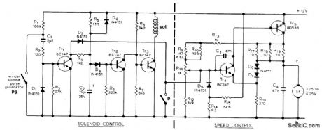
Used in high-quality stereo cassette deck operating from AC line or battery. Combines current source for cassette-retaining solenoid with speed control for drive motor. As motor turns, associated motor-driven pulse-generating switch keeps Tr1, conducting; this cuts off Tr2 and allows current to flow through Tr3 for energizing solenoid. When motor stops, pulse-generating switch also stops and Tr1 stops con-ducting. After 3-s delay determined by C2 and R5, Tr2 conducts and solenoid is deenergized, releasing cassette. In speed control circuit, Tr5 acts as constant-current source for motor, using feedback from its collector to base of Tr4 Back EMF developed by motor is applied to emitter of Tr4 reducing its forward bias and reducing current In the base of Tr5, so as to stabilize motor Article gives all other circuits of cassette deck and describes operation in detail.-J. L. Linsley Hood, Low-Noise, Low-Cost Cassette Deck, Wireless World, Part 3-Aug.1976,ρ55-56(Part 1-May 1976,p 36-40, Part 2-June 1976.p62-66.) (View)
View full Circuit Diagram | Comments | Reading(1321)
100_W_AT_432_MHz
Published:2009/7/7 2:08:00 Author:May

Two-transistor 100-W PEP solid-state linear amplifier can be used for SSB activity in satellite relay service or for linear, CW, or FM service. Circuit uses Motorola MRF30628-V 60-W 225-400 MHz power tran-sistors in narrow-band parallel amplifier oper-ating in class AB linear mode. Drive level is about 10 W PEP. Article covers construction and tune-up.-R. K. Olsen, 100-Watt Solid-State Power Amplifier for 432 MHz, Ham Fladio, Sept.1975, p 36-43. (View)
View full Circuit Diagram | Comments | Reading(1423)
20_KC_WIRETRACING_PROBE
Published:2009/7/21 22:30:00 Author:Jessie
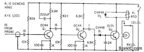
Used lo identify wire in middle of long cable, carrying 20-kc mvbr signal. Pickup probe for amplifier has 600 turns wound on U-shaped trans former steel. Relay doses and energizes lamp when probe is held near correct wire.-J. S. Rushton, Probe Identifies Catble Wiring, Electronics, 34:9, p 51. (View)
View full Circuit Diagram | Comments | Reading(684)
2_3Q_MHz_14Q_W_LINEAR
Published:2009/7/7 2:05:00 Author:May
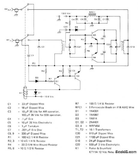
Uses two Motorola. MRF454 transistors Q3-Q4 in circuit providing relatively flat gain over frequency band, as required for power amplifier of amateur SSB transmitter. Bias diode D2 is mounted on heatsink of Q3-Q4 for temperature tracking. Circuit includes carrier-operated relaydriven by Q1 and - Q2.-T. Bishop, 14QW (PEP) Amateur RadioLinear Amplifier 2-3QMHz, Motorola, Phoenix,AZ, 1976, EB-63. (View)
View full Circuit Diagram | Comments | Reading(1380)
Time_sequencer_using_ECG955M_timer_oscillator_chips
Published:2009/7/21 22:30:00 Author:Jessie
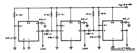
Time sequencer using ECG955M timer/oscillator chips. The first timer is started by momentarily connecting pin 2 to ground. It runs for 10 ms, then triggers the second timer. The second one runs for 50 ms, at which time it triggers the third. Note that the timing resistors and capacitors can be programmed and that each circuit could trigger several other timers (courtesy GTE Sylvania Incorporated). (View)
View full Circuit Diagram | Comments | Reading(825)
1_Hz_TO_100kHz_SQUARE_TRAINGLE
Published:2009/7/7 2:04:00 Author:May
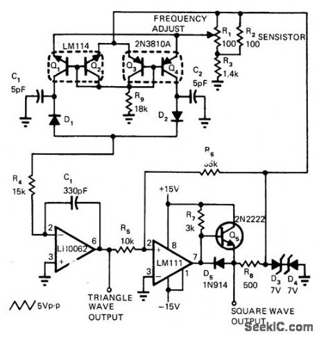
Wid el range function generator built around LM111 comparator provides two different output waveforms whose frequency can be varied over five decades by R,, from 1 Hz to 100 kHz. Two transistor pairs are used to vary charging current of timing capacitor exponentially. Output current fromtransistor pairs is controlled by linear pot, so rotation of pot is proportional to log of output frequency. Sensistor R2 provides temperature compensation for transistor pairs.-R.C. Dobkin, Comparators Can Do More Than Just Compare, EDN Magazine, Nov. 1,1972, p 34-37. (View)
View full Circuit Diagram | Comments | Reading(580)
25_Hz_TO_250_kHz_SQUARE_TRIANGLE
Published:2009/7/7 1:57:00 Author:May
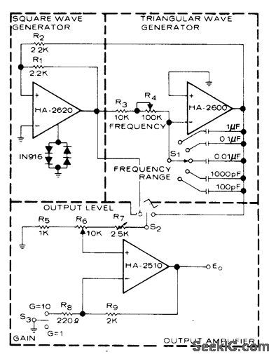
Five switched frequency ranges each give continuous variation of frequency over one decade and adjustment of output amplitude from 0.2 to 20 V P-P. Slope of triangle is highly linear, and rise time of square wave is less than 100 ns. Squarewave generator is simple hysteresis circuit triggered by triangle generator. Output voltage is clamped to desired level by diodes connected to bandwidth control point. Output opamp is selected for high slew rate. S3 gives choice of 1 or 10 for gain. Maximum output current should be limited to 2O mA.- Linear & Data Acquisition Products, Harris Semiconductor, Melboume, FL, Vol. 1,1977, p 7-25 (Application Note 510). (View)
View full Circuit Diagram | Comments | Reading(572)
UNDER_OVERSPEED_LOGIC
Published:2009/7/7 1:57:00 Author:May
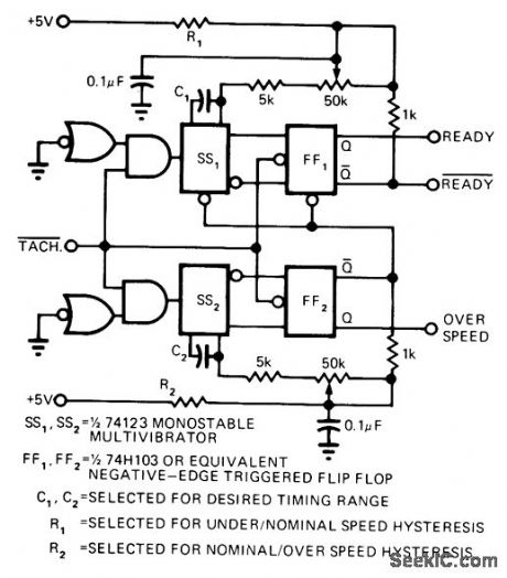
Provides signal (READY output high} only when tachometer pulses from motor are within specific upper and lower limits. Also provides over speed output signal when upper limit has been exceeded. Single-action triggering eliminates instability at decision point. Article covers circuit operation in detail and gives timing diagram.-W. Bleher, Circuit Indicates Logic Ready, EDN Magazine, March 5, 1974, p 72 and 74. (View)
View full Circuit Diagram | Comments | Reading(742)
TRANSISTOR_TESTER_3
Published:2009/7/21 22:30:00 Author:Jessie
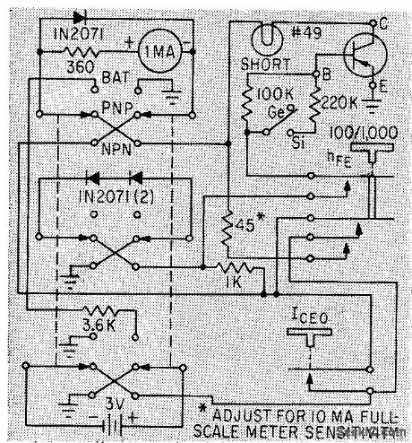
Leakage current and common-emitter current amplification are checked by using forward voltage drop across two silicon rectifiers in series as reference voltage. Base current of transistor under test is held constant by switching series base resistance.-G. F. Montgomery, Buildinga Simple Transistor Tester, Electronics, 36:16, p 56. (View)
View full Circuit Diagram | Comments | Reading(677)
FOUR_PHASE_STEPPER_DRIVE_EXCLUSIVE
Published:2009/7/7 1:54:00 Author:May
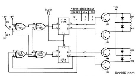
OR gates of 7486 provide steering, while 7476 flip-flops provide memory for generating drive patterns of bidirectional logic stepper motor that is controlled by microprocessor. Output transistors, diodes, and resistors are chosen to meet power requirements for each phase of motor. Speed is controlled by frequency of clock input. Use 555 for coarse control or crystal oscillator for accurate control. S1, which can be an I/O line of microprocessor, controls direction of rotation. Frequency can be obtained from digitally controlled oscillator whose setting is determined by DAC.-R. E. Bober, Taking the First Step, BYTE, Feb. 1978, p 35-36, 38, 102, 104, 106, and 108-112. (View)
View full Circuit Diagram | Comments | Reading(2639)
Precision_programmable_timers_using_the_Intersil_8240_8250_16_pin_DIP
Published:2009/7/21 22:29:00 Author:Jessie
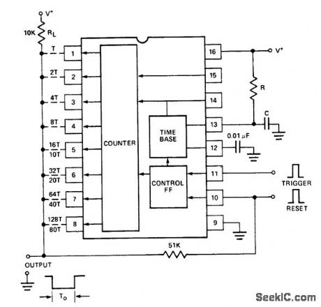
Precision programmable timers using the Intersil 8240/8250 16-pin DIP. The timer is used in the monostable mode. The output is normally high and goes low to trigger an input. Components R and C at pin 13 determine the time cycle. The timing duration, TO is equal to NBC, where R and C are component values and N is a number between 1 and 255. Integer N is determined by the combination of pins 1 through 8 connected to the output bus. The 8250 can be programmed for numbers between 1 and 99. The numbers shown on the schematic adjacent to pin 1 through 8 are the respective N integers, with the upper ones for the 8240 and the lower ones for the 8250 (courtesy Intersil, Inc.). (View)
View full Circuit Diagram | Comments | Reading(1082)
SPEED_CONTROL_FOR_3_V_MOTOR
Published:2009/7/7 1:51:00 Author:May
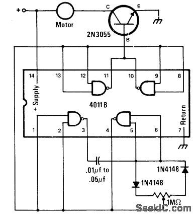
Designed for use with hobby or toy motors running at about 10,000 rpm and powered by 3-V to 6-V batteries. Uses 4011 CMOS NAND gate with diodes and power transistor to provide variable duty cycle, so adjustment of 1-megohm speed control varies average voltage applied to motor without affecting peak voltage. Motor battery is connected between + terminal and ground of circuit.-J. A. Sandier, 11 Projects under $11, Modern Electronics, June 1978, p 54-58. (View)
View full Circuit Diagram | Comments | Reading(871)
TIME_BASE_GENERATOR
Published:2009/7/21 22:28:00 Author:Jessie
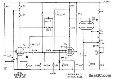
Variable time delay V8-V9 permits selecting portions of cro display in pulse-echo cable fault finder. Adjustment range is 190 to 1,140 microsec, or 10 to 60 nautical miles.-F. Jones and J. H. Reyner, Compact New Instrument Finds Undersea Cable Faults, Electronics, 35:37, p 48-50. (View)
View full Circuit Diagram | Comments | Reading(1222)
SINE_SQUARE_TRIANGLE_WITCH_LIN_LOG_SWEEP
Published:2009/7/7 1:51:00 Author:May
Four-tran sistor circuit provides choice of linear or logarithmic sweeps for Intersil 8038 IC function generator. In linear mode, constant-current generator Tr3 charges C1 almost linearly, with Tr1-Yr2 resetting C1 when its voltage reaches about one-third VCC plus 0.9 V.In logarithmic mode, positive feedback provides exponential charging of C1. Voltage at B must be set experimentally because it depends on VCC For overall frequency control, make R5variable. Point A has short positive pulse that can be used to reset capacitor C of IC, and to sync an oscilloscope.-S. Villone, Linear/Logarithmic Sweep Generator, Wireless World, Dec.1976, p 42. (View)
View full Circuit Diagram | Comments | Reading(2427)
WIDEBAND_ACTIVE_PHASE_SHIFTER
Published:2009/7/21 22:27:00 Author:Jessie
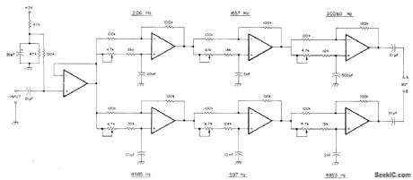
Active audio phase-shift network uses two LM324 quad opamps to provide equal amplitude outputs differing in phase by 90°±2° from 100 Hz to 10 kHz. Each stage is adjusted with 4.7K trim-pot to give 90° phase shift at frequency shown on diagram. Align with audio oscillator and CRO or phase meter. Operates from single 5-V supply. Overall gain of entire circuit is unity.-R.Harrison, A Review of SSB Phasing Techniques, Ham Radio, Jan. 1978, p 52-62. (View)
View full Circuit Diagram | Comments | Reading(4472)
STEP_COUNTER_FOR_STEPPER
Published:2009/7/7 1:48:00 Author:May
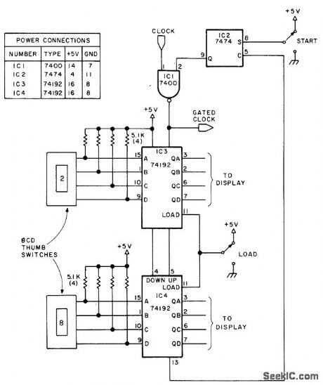
Used to deliver selected number of pulses to stepper motor when start button is pushed, in micro-processor application where number of steps is more important than precise speed. Thumb-wheel switch inputs can be I/O port lines of microprocessor. LOAD line transfers into counter the desired count as set up by switches. Article gives flowcharts and software routines for microprocessor to be used for controlling stepper motor.-R. E. Bober, Taking the First Step, BYTE, Feb. 1978, p 35-36, 38, 102, 104, 106, and 108-112. (View)
View full Circuit Diagram | Comments | Reading(1757)
20_KC_WIRE_TRACING_MVBR
Published:2009/7/21 22:27:00 Author:Jessie
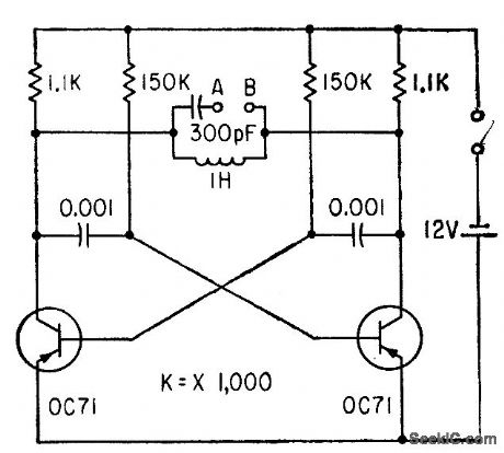
Used as signal source for identifying particular wire at midpoint in cable, for splicing. Ends of wire are connected between A and B, to become part of parallel-tuned circuit of astable mvbr. Tiny probe coil with amplifier is then used to locate wire carrying 20-kc signal.-J. S. Rushton, Probe Identifies Cable Wiring, Electronics, 34:9, p 51. (View)
View full Circuit Diagram | Comments | Reading(682)
SERIES_MOTOR_SPEED_CONTROL
Published:2009/7/7 1:45:00 Author:May
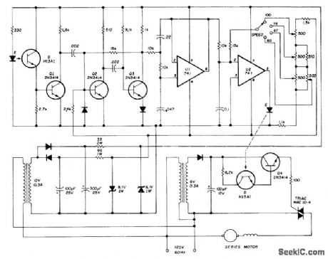
Adjustable-speed solid-state motor drive replaces governor in Kleinschmidt RTTY page printer, to give knob-controlled speed range of 60 to 100 WPM.Notched (33-slot) sheet-aluminum disk serving as pulse wheel is mounted on motor shaft and rotates in gap bemoan LED and phototransistor of GE H13A1 optical coupler to form motor-speed sensor or tachometer. Pulses from tachometer, squared by Q1, trigger mono MVBR Q2-Q3 which converts signal to constant-amplitude constant-width pulses having repetition rate proportional to motor speed. Opamp U1 forms three-pole Butterworth active filter that develops required average DC voltage from pulse train. Output current of U1 is compared to reference current derived from speed control circuit, for switching U2 sharply on and off as speed varies above and below desired value. U2 in turn switches motor on and off through H15A1 optical coupler and Q4 in gate circuit of triac. Second coupler isolates control circuit from AC line.-K. H. Sucker, Electronic Speed Control for RTTY Machines, Ham Radio, Aug.1974,p50-54. (View)
View full Circuit Diagram | Comments | Reading(1131)
POSITIVE_RAMP
Published:2009/7/7 1:45:00 Author:May
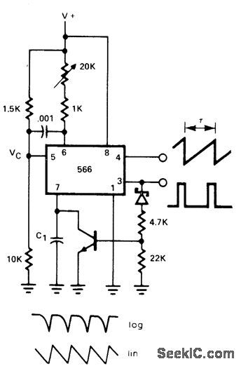
NPN transistor across timing capacitor C1 of 566 function generatorgives fast charging of capacitoratend of dischargeperiod, for positive ramp having very fast reset. Period of ramp is equal to 1/2f where f is normal freerunning frequency of 566 as determined by supply voltage and RC values used.- Signetics Analog Data Manual, Signetics, Sunnyvale, CA, 1977, p 851. (View)
View full Circuit Diagram | Comments | Reading(753)
HI_FI_EXPANDER_WITH_DE_EMPHASIS
Published:2009/7/7 1:43:00 Author:May
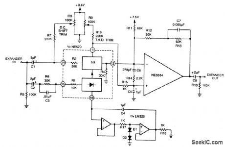
The expander to complement the compressor is shown. An external op amp is used for high slew rate. Both the compressor and expander have unity gain levels of 0 dB. Trim networks are shown for distortion (THD) and dc shift. The distortion trim should be done first, with an input of 0 dB at 10 kHz. The dc shift should be adjusted for minimum envelope bounce with tone bursts. When applied to consumer tape recorders, the subjective performance of this system is excellent. (View)
View full Circuit Diagram | Comments | Reading(1226)
| Pages:1006/2234 At 2010011002100310041005100610071008100910101011101210131014101510161017101810191020Under 20 |
Circuit Categories
power supply circuit
Amplifier Circuit
Basic Circuit
LED and Light Circuit
Sensor Circuit
Signal Processing
Electrical Equipment Circuit
Control Circuit
Remote Control Circuit
A/D-D/A Converter Circuit
Audio Circuit
Measuring and Test Circuit
Communication Circuit
Computer-Related Circuit
555 Circuit
Automotive Circuit
Repairing Circuit