
Circuit Diagram
Index 986
SECURITY_DOOR_AJAR_ALARM
Published:2009/7/7 7:27:00 Author:May
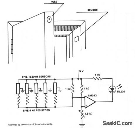
In operation, the TL3019 device will activate, or become low, when a south pole of a magnet comes near the chip face of the device. The example shows five doors. Each door has a magnet embedded in its edge with the south pole facing the outer surface. At the point where the magnet is positioned with the door closed, a TL3019 sensor is placed in the door jamb. With the door closed, the Hall devices will be in a logic low state. This design has five doors and uses five TL3019 devices. Each TL3019 has a 4-KΩ resistor in series and all door sensor and resistor sets are in parallel and connected to the inverting input of an LM393 comparator. With all doors closed, the effective resistance will be about 800 0 and produce 2.2 V at the inverting input. The noninverting input goes to a voltage divider network which sets the reference voltage. The 1.5-KΩ potentiometer is adjusted so the indicator goes out with all doors closed. This will cause 2.35 V to appear at the noninverting input of the comparator. When a door opens, the voltage at the inverting input will go to 2.5 V which is greater than VREF, and the LED will light. A large number of doors and windows can be monitored with this type of circuit. Also, it could be expanded to add an audible alarm in addition to the visual LED. (View)
View full Circuit Diagram | Comments | Reading(1075)
Color_TV_chroma_processor
Published:2009/7/21 8:12:00 Author:Jessie
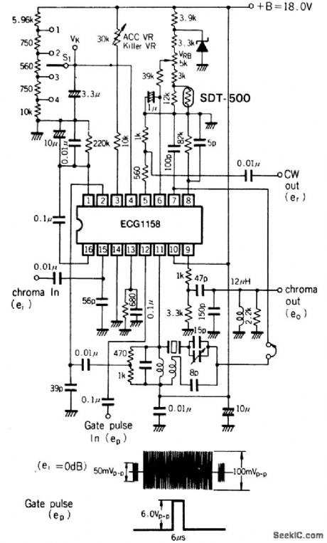
Color TV chroma processor. The ECG1158 includes the functions for chroma amplifier, oscillator, ACC, color killer and color control (courtesy GTE Sylvania Incorporated). (View)
View full Circuit Diagram | Comments | Reading(710)
TEMPERATURE_COMPENSATED_CRYSTAL_OSCILLATOR
Published:2009/7/7 7:27:00 Author:May
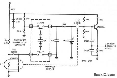
This circuit uses LTC1043 to differentiate between a temperature sensing network and a dc reference. The single-ended output biases a varactor-tuned crystal oscillator to compensate drift. The varactor crystal network has high dc impedance, eliminating the need for an LTC1043 output amplifier.
(View)
View full Circuit Diagram | Comments | Reading(0)
CRYSTAL_CONTROLLED_REFLECTION_OSCILLATOR
Published:2009/7/7 7:25:00 Author:May
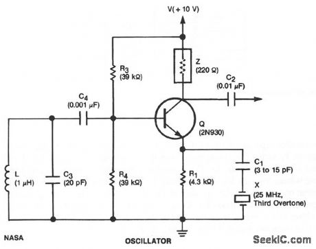
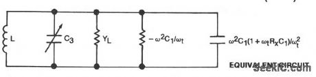
This unit is easily tunable and stable, consumes little power, and costs less than other types of oscillators that operate at the same frequencies. This unusual combination of features is made possible by a design concept that includes operation of the transistor well beyond the 3 dB frequency of its current-versus-frequency curve. The concept takes advantage of newly available crystals that resonate at frequencies up to about 1 GHz.
The emitter of transistor Q is connected with variable capacitor C1 and series-resonant crystal X.The emitter is also connected to ground through bias resistor R1. The base is connected to the parallel combination of inductor L and capacitor C3 through dc-blocking capacitor and C4 and is forward biased with respect to the emitter by resistors R3 and R4. Impedance Z could be the 220-Ω resistor shown or any small impedance that enables the extraction of the output signal through coupling capacitor C2. If Z is a tuned circuit, it is tuned to the frequency of the crystal. (View)
View full Circuit Diagram | Comments | Reading(900)
Half_wave_average_voltage_control_circuit_for_a_600_watt_load
Published:2009/7/21 8:11:00 Author:Jessie
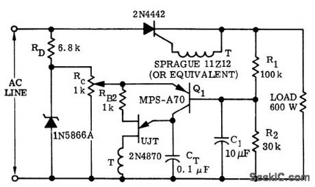
Half-wave average voltage control circuit for a 600-watt load (courtesy Motorola Semiconductor Products Inc.). (View)
View full Circuit Diagram | Comments | Reading(596)
DYNODE_TO_GRID_POSITIVE_FEEDBACK
Published:2009/7/21 8:11:00 Author:Jessie
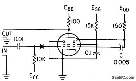
Produces negative output pulse across plate load of secondary-emission pentode. Feedback is from dynode to control grid, rather than from plate to cathode. Diode insures that feedback pulse does not affect other circuits, und makes feedback nearly independent of input generator impedance. Used in high-speed, short. duration pulse work.-E. J. Martin, Jr., How to Use the Secondary-mission Pentode, Electronics, 33:41, p 60-63. (View)
View full Circuit Diagram | Comments | Reading(646)
VOLTAGE_SENSING
Published:2009/7/21 8:11:00 Author:Jessie
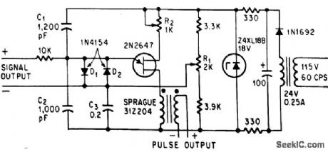
Unijunction transistor is triggered when input signal is slightly positive, and then generates pulses as long us input remains positive. Output con be used to trigger flip-flop or turn on scr's.-D. V. Jones, Quick-On-The-Trigger Design, Electronics, 38:12, p 105-110. (View)
View full Circuit Diagram | Comments | Reading(754)
CURRENT_MONITOR
Published:2009/7/7 7:23:00 Author:May
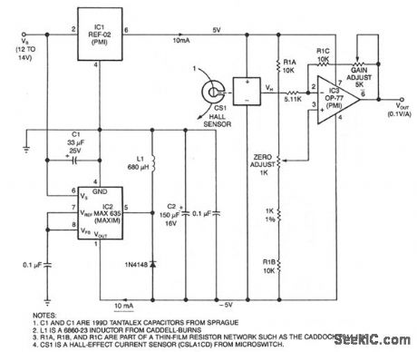
This circuit uses a Hall-effect sensor, consisting of an IC that resides in a small gap in a flux-collector torrid, to measure dc current in the range of 0 to 40 A. You wrap the current-carrying wire through the toroid; the Hall voltageVH is then linearly proportional to current I. The current drain from VB is less than 30 mA.To monitor an automobile alternator's output current, for example, connect the car battery between the circuit's VB terminal and ground, and wrap one turn of wire through the toroid. Or, you could wrap 10 turns-if they fit-to measure 1 A full scale. When I = 0 V current sensor CSI'sVH output equals one-half of its 10 V bias voltage. Because regulators IC1 and IC2 provide a bipolar bias voltage,VH and VOUT are zero when I is zero; you can then adjust the output gain and offset to scaleVOUT at 1 V per 10 A. (View)
View full Circuit Diagram | Comments | Reading(0)
Full_wave_trigger_circuit_for_a_900_watt_load_using_a_triac_and_UJT
Published:2009/7/21 8:10:00 Author:Jessie
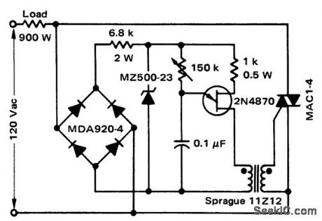
Full-wave trigger circuit for a 900-watt load using a triac and UJT (courtesy Motorola Semiconductor Products Inc.). (View)
View full Circuit Diagram | Comments | Reading(1263)
SMOKE_DETECTOR_2
Published:2009/7/7 7:18:00 Author:May
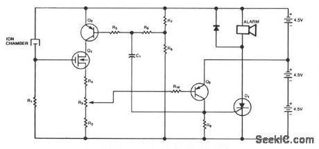
This circuit comes from U.S. Patent 3,778,800, granted to BRK Electronics in Aurora, IL. The circuit provides a smoke detector with an alarm for both smoke and low batteries. The R6/R7 voltage divider monitors the battery and will turn Q2 and Q1 off when the battery voltage falls too low. The smoke-detec-tor chamber will also cut Q1 off when it senses smoke. Q1 via Q3, triggers SCR Dl and sounds the alarm. Capacitor C1 provides feedback that causes the alarm to sound intermittently. The smoke detector and low-battery circuits sound the alarm at two different rates. (View)
View full Circuit Diagram | Comments | Reading(912)
TV_video_processor
Published:2009/7/21 8:10:00 Author:Jessie
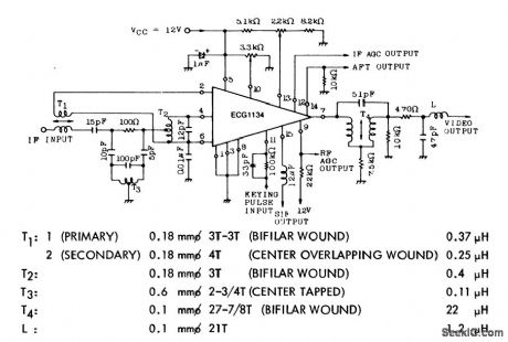
TV video processor. The EGG 1134 contains a picture IF amplifier, avideo detector,a video amplifier,keyed AGC with noise immunity, delayed AGC for thetuner, an AFT amplifier, a sound IF amplifier, asound carrier detector, a4.5 MHz sound carrier amplifier and a reverse AGC voltage for MOS FET tuner. Coil data is shown below schematic (courtesy GTE Sylvania Incorporated). (View)
View full Circuit Diagram | Comments | Reading(2532)
TWO_GATE_QUARTZ_OSCILLATOR
Published:2009/7/7 7:18:00 Author:May
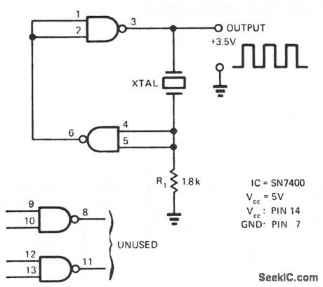
A SN7400 quartz crystal and a resistor provide a square-wave output of approximately 3.5 V. The circuit operates reliably at frequencies from 120 kHz to 4 MHz. (View)
View full Circuit Diagram | Comments | Reading(2477)
SERIES_SCHMITT
Published:2009/7/21 8:10:00 Author:Jessie
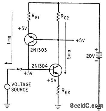
Complementary transistors are either both on or both off, conserving power for trigger, comparator, flip-flop, one shot, and oscillator applications. With 20,v supply, RB1 is 15 K, RC2 is 3K, and RE2 is 1K.-J. K. Skilling, New Complementary Transistors make Series Schmitt Circuits Practical, Electronics, 35:35, p 52-53. (View)
View full Circuit Diagram | Comments | Reading(1417)
GAS_SMOKE_DETECTOR
Published:2009/7/7 7:17:00 Author:May
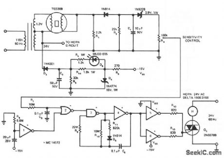
In the presence of smoke or gas, the ac output voltage increases and becomes rectified, filtered and zener-diode coupled (D2 for thresholding) to sensitivity control R3. Under no gas condition, the output equals approximately 0 V (high). When gas is present, the output will be a negative value (low) sufficient to overcome the threshold of McMOS gate 2 and D2. The circuit shown uses a TGS 308 sensor, a general-purpose gas detector that is not sensitive to smoke or carbon monoxide. If smoke is the primary element to be detected, use the TGS 202 sensor. The two sensors are basically identical; the main differences lie in the heater voltage and the required warm up time delay. The TGS requires a 1.2 V heater and a 2 minute delay, whereas the TGS 202 requires 1.5 V and 5 minutes, respectively.The system uses a McMOS gated oscillator directly interfacing with a triac-controlled ac horn. Using the MC14572 HEX functional gate, four inverters, one two-input NAND gate and one two-input NOR gate, the circuit provides the complete gas/smoke detector logic functions time delay, gated astable multi-vibrator control and buffers operation. The 24-Vac ham produces an 85/90-dB sound level output at a dis-tance of 10 ft. Controlled by the astable multivibrator, the ham generates a pulsating alarm-a signal that may be advantageous over a continuous one in some noise environments. (View)
View full Circuit Diagram | Comments | Reading(1279)
175_SCHMITT
Published:2009/7/21 8:09:00 Author:Jessie
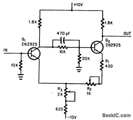
Use of inexpensive transistors and fixed resistors in place of potentiometers keeps cost low. Hysteresis control R2 and trigger level control R3 are optional. Output is 8 v peak to peak at 50 kc.-A. Pacela, Low-Cost Schmitt Trigger Reduces Hysteresis, Electronics, 38:24, p 63-64. (View)
View full Circuit Diagram | Comments | Reading(618)
VOLTAGE_CONTROLLED_CRYSTAL_OSCILLATOR
Published:2009/7/7 7:16:00 Author:May
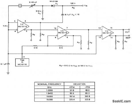
A voltage-variable capacitance tuning diode is placed in series with the crystal feedback path. Changing the voltage on VR varies the tuning diode capacitance and tunes the oscillator. The 510-KΩ resistor, R1, establishes a reference voltage for VR-ground is used'm this example. A 100-KΩ resistor, R2, isolates the tuning voltage from the feedback loop and 0.1-μF capacitor C2 provides ac coupling to the tuning diode. The circuit operates over a tuning range of 0 to 25 V. It is possible to change the tuning range from 0 to 25 V by reversing the tuning diode Dl. Center frequency is set with the 2 -60 pf trimmer capacitor.Deviation on either side of center is a function of the crystal frequency. The table in Fig. 21-7 shows mea-sured deviation in parts per million for several tested crystals. (View)
View full Circuit Diagram | Comments | Reading(1871)
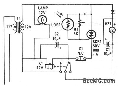
SCR_SMOKE_ALARM
Published:2009/7/7 7:15:00 Author:May
View full Circuit Diagram | Comments | Reading(703)
SMOKE_DETECTOR_1
Published:2009/7/7 7:15:00 Author:May
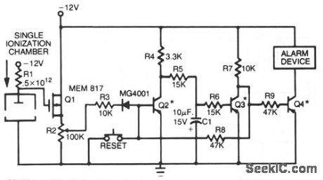
This smoke detector uses a MEM 817 p-channel enhancement mode MOSFET as its buffer amplifier. Operation of the sensor is based on a decrease in the current when smoke enters the chamber, thereby causing a negative voltage excursion at the gate of the buffer MOSFET. Quiescent voltage values at the output of the chamber vary from about -4 V to -6 V, and detection of smoke will result in an excursion of about -4 V. The MOSFET is connected as a source follower. (View)
View full Circuit Diagram | Comments | Reading(801)
LOW_FREQUENCY_PIERCE_OSCILLATOR
Published:2009/7/7 7:14:00 Author:May
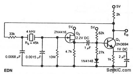
The Pierce circuit oscillates at 4 kHz.At low frequencies,the crystal's internal senes resistance RS isquite high (45 K at 4 kHz).Therefore,all FET-based source follower is included to prevent Q1 from loading the crystal output. (View)
View full Circuit Diagram | Comments | Reading(1054)
FURNACE_EXHAUST_GAS_TEMPERATURE_MONITOR_WTH_LOW_SUPPLY_DETECTION
Published:2009/7/7 7:13:00 Author:May
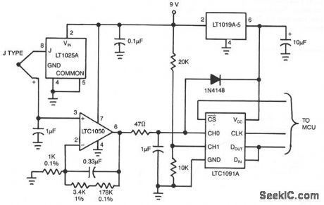
This circuit can be used to measure exhaust gas temperature m a furnace. The 10-bit LTC1091A gives 0.5°C resolution over a 0°C to 500°C range. The LTC1050 amplifies and filters the thermocouplesignal, the LT1025A provides cold junction compensation and the LT1019A provides an accurate reference. The J-type thermocouple characteristicis linearized digitally inside the MCU. Linear interpolationbetween known temperature points spaced 30°C apart introduces less than 0.1°C error.The 20-K/10 ΚΩdivider on CH1 of the LTC1091 provides low supply voltage detection,Remote locationis easy, with datatransferred from the MCU to the LTC1091 via the three wlre serial part. (View)
View full Circuit Diagram | Comments | Reading(840)
| Pages:986/2234 At 209819829839849859869879889899909919929939949959969979989991000Under 20 |
Circuit Categories
power supply circuit
Amplifier Circuit
Basic Circuit
LED and Light Circuit
Sensor Circuit
Signal Processing
Electrical Equipment Circuit
Control Circuit
Remote Control Circuit
A/D-D/A Converter Circuit
Audio Circuit
Measuring and Test Circuit
Communication Circuit
Computer-Related Circuit
555 Circuit
Automotive Circuit
Repairing Circuit