
Circuit Diagram
Index 999
SSB_AVERAGE_CURRENT_METER
Published:2009/7/21 21:08:00 Author:Jessie
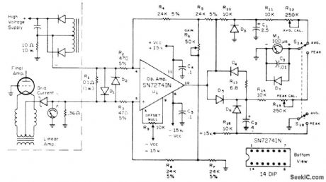
Uses con-trolled time constant of 1/4 s to generate good approximation of average current in voice-modulated SSB signal. Circuit also gives peak current reading, with peaks measured and held for short time. Opamp isolates current from plate supply and converts it into signal that can be run through shaping network to get averages and peaks. D1-D7 are 1N3064 or equivalent. D1 and D2 eliminate spikes that might damage opamp R6 allows small adjustments of opamp gain, which is normally set at 100.-R Sans, Make Your Meter Readings Count,CQ.Dec.1972,P28-29. (View)
View full Circuit Diagram | Comments | Reading(967)
PRODUCT_DETECTOR
Published:2009/7/21 21:06:00 Author:Jessie
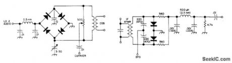
Developed for use in SSB receiver having 9-MHz IF amplifier. Values in parentheses are for receiver having 455-kHz IF amplifier. Diode types are not critical.-Circuits, 73Magazine, May 1973, p 105. (View)
View full Circuit Diagram | Comments | Reading(7575)
HF_VHF_MARKERS
Published:2009/7/21 21:05:00 Author:Jessie
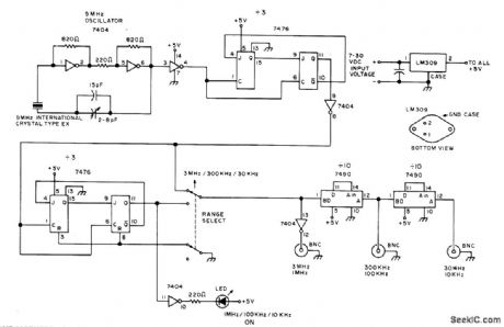
Provides markers needed for most amateur radio bands, including 30 and 300 kHz for VHF FM operation and 10 and 100 kHz for 2-m FM operation. When LED is on, outputs are 1 MHz, 100 kHz, and 10 kHz. When LED is off, outputs are 3 MHz, 300 kHz, and 30 kHz. Uses 7404 TTL hex inverter as crystal oscillator, with 2-8 pF trimmer for zeroing crystal with WWV. All 7476 TTL dual JK flip-flops are connected to divide by 3.-F. E, Hinkle, Inexpensive HF-VHF Frequency Standard, 73 Magazine, April 1976, p 62-63. (View)
View full Circuit Diagram | Comments | Reading(905)
CONTINUOUS_DUTY_BRAKE
Published:2009/7/7 3:33:00 Author:May
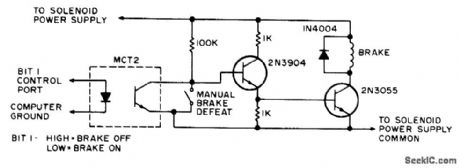
High or 1 bit at output port of microprocessor energizes brake solenoid of paper-tape reader through optocoupler and amplifier,When tape is to be stopped, brake solenoid is energized and tape is squeezed between top of solenoid and flat iron brake shoe that is attracted by solenoid.-D. Hogg、The Paper Taper Caper, Kilobaud, March1977,p 34-40. (View)
View full Circuit Diagram | Comments | Reading(4165)
455_kHz_FREQUENCY_MODULATED
Published:2009/7/21 21:03:00 Author:Jessie
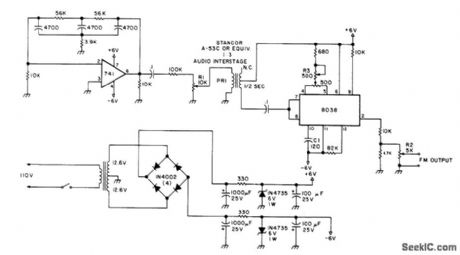
Can be used to align IF amplifier and quadrature detector of FM receivers. Unit is stable and provides ample deviation for amateur receivers. Uses 8038 function generator and 741 opamp connected as audio oscillator to provide about 1000-Hz modulating voltage. Includes deviation control R1, output level control R2, and carrier frequency control R3. Adjust 500-ohm pot between pins 4 and 5 of 8038 for clean sine-wave output on CRO. Adjust R3 to give 455 kHz as measured by meter or frequency counter. To check audio oscillator, connect AC voltmeter or CRO across R1, which should have clean 1000Hz sine wave of several hundred millivolts. Transformer in power supply can be two separate 12.6-V units with primaries in parallel and secondaries in series.-J. C. Chapel, Build This FM Signal Generator, 73Magazine, Jan. 1978, p 154-155. (View)
View full Circuit Diagram | Comments | Reading(1664)
TEMPERATURE_TRANSMlTTER
Published:2009/7/21 20:55:00 Author:Jessie
2N169A transistor is used in tuned-collector oscillator, with large R.C time constant in emitter drcuit to give self-modulator for quenching action. Variation in quench break is accomplished with temperature-sensing element R1, consisting of glass-enclosed bead thermistor.-R. H. Elsken, Temperature Telemetry Aids Frozen Food Study, Electronics, 33:33, p 129-131. (View)
View full Circuit Diagram | Comments | Reading(854)
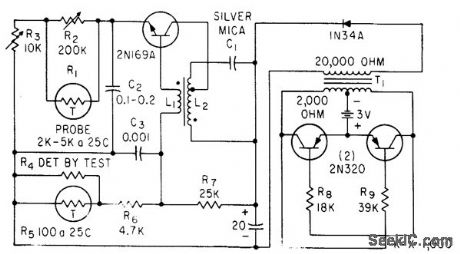
ROAD_ICING_ALARM
Published:2009/7/21 20:54:00 Author:Jessie
Sensing transmitter mounted on auto about 2 feel above rood, with junction of transistor connected to case is connected to low-frequency oscillator having lamp load. R7 is adjusted so lamp is out but on verge of flashing of 2℃. When temperature drops, lamp flashes. Duration of each lash increases down to 0℃ after which lamp remains on.-J. A. Irvine, Reducing Winter Skids with a Transistor Warning Circuit, Electronics, 36:4, p 56-58. (View)
View full Circuit Diagram | Comments | Reading(757)
Manual_512_bit_PROM_programmer
Published:2009/7/21 20:53:00 Author:Jessie
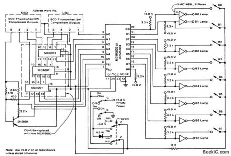
Manual 512-bit PROM programmer (courtesy Motorola Semiconductor Products Inc.). (View)
View full Circuit Diagram | Comments | Reading(784)
MEASURING_HIGH_TEMPERATURES
Published:2009/7/21 20:51:00 Author:Jessie
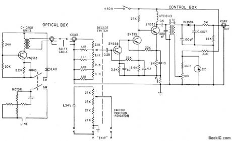
Used for automatic recording of missile und rocket surface temperatures. Phototransistor, connected in common-emitter mode, requires no preamp. Decade amplifier in control box is stabilized by 34 db of feedback through R1. Diode demodulator provides d-c output for recording.-S. A. Elder, Designing Photo. transistor Pyrometers With and Without Feed. bock, Electronics, 34:49, p 56-60.
(View)
View full Circuit Diagram | Comments | Reading(1131)
TRANSISTORS_SENSE_TEMPERATURE
Published:2009/7/21 20:45:00 Author:Jessie
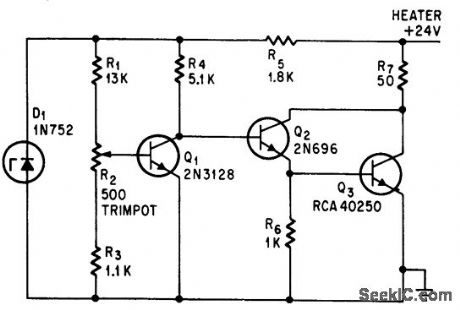
Transistor Q1, nounted in tight thermal contact with heater R7, will maintain crystal oven within 0.2℃ of 70℃.-S. Greenblatt, Transistor Be-comes Sensor In Temperature Regulator, Electronics, 37:28, p 65. (View)
View full Circuit Diagram | Comments | Reading(1069)
SIMPLE_DIODE_SENSOR
Published:2009/7/21 20:44:00 Author:Jessie
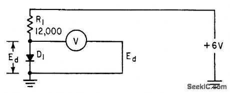
Meter measures voltage drop across germanium diode (such as 1N2326), which varies linearly with temperature from near absolute zero to a high limit around 45℃, which is upper limit of diode base material.-L. E. Barton, Measuring Temperature with Diodes and Transistors, Electronics, 35;18, p 38-40. (View)
View full Circuit Diagram | Comments | Reading(793)
PULSE_TRAIN_AMPLITUDE_MODULATOR
Published:2009/7/22 1:13:00 Author:Jessie
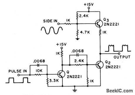
Provides amplitude modulation of pulse train with audio signal or other input, such as noise, over range of 0 to 200 kc with :input pulses over 1 microsec wide,80% modulalation is available up to 3 kc, decreasing to 30% at input of 200 kc,-J. F. McCormick,Jr, Pulse Amplitude Modulator, EEE. 13:7,p 44. (View)
View full Circuit Diagram | Comments | Reading(2947)
MANUALLY_CONTROLLED_SIREN
Published:2009/7/22 1:12:00 Author:Jessie
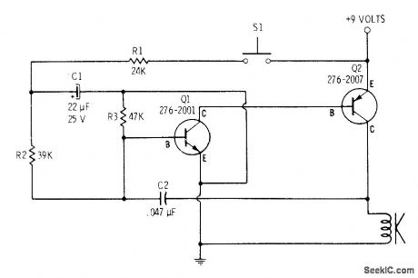
When switch is pressed, output tone of loudspeaker builds from low to high frequency. Releasing switch brings high frequency slowly back to low point and then cutoff. Siren sounds can be varied manually by pushing and releasing switch at different points in cycle.C2 controls pitch, and R3 determines speed at which pitch changes.-F. M. Mims, Transistor Projects, Vol. 1, Radio Shack, Fort Worth, TX, 1977, 2nd Ed. p 58-63. (View)
View full Circuit Diagram | Comments | Reading(669)
TRANSFORMERLESS_LINEAR_MODULATOR
Published:2009/7/22 1:11:00 Author:Jessie
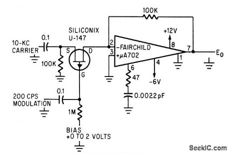
Integrated-circuit operational amplifier and field effect transistor in single-ended linear configuration eliminate need for filter and transformer. Carrier level is adjusted by changing d-c bias, which sets gate midway between zero bias and pinchoff.-J. Althouse, linear Amplifier Circuit Eliminates Transformers, Electronics, 39:6, p 99. (View)
View full Circuit Diagram | Comments | Reading(608)
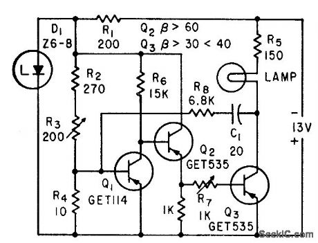
100_MODULAIION_OF_LIGHT_EMITTING_DIODE
Published:2009/7/22 1:10:00 Author:Jessie
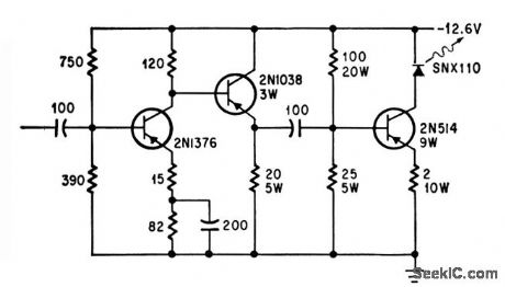
Inpt of 0.35 v rms at 1 kc gives 100% modulation. Useful operating range of circuit is 30 cps to 25 kc for light-beam communication.-E. t. Bonin, Drivers for Optical Diodes, Electronics, 37:22, p 77-82. (View)
View full Circuit Diagram | Comments | Reading(656)
Basic_triac_zero_point_switch
Published:2009/7/21 23:16:00 Author:Jessie
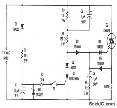
This circuit shows a manually controlled zero-point switch that is useful in power control for resistive loads. Q2 turns on near zero on both the positive and negative half-cycles of the line input. When S1 is closed, Q1 turns on, shunts gate current away from Q2, and keeps Q2 from turning on during either half cycle. The 2N6346 triac shown will handle resistive loads up to 8 A. (View)
View full Circuit Diagram | Comments | Reading(1168)
PLL_clock_for_a_ADC1100_BCD_dual_slope_A_D_convener
Published:2009/7/21 23:16:00 Author:Jessie
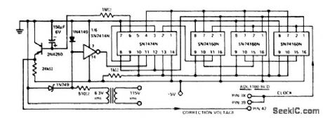
PLL clock for a ADC1100/BCD dual-slope A/D convener (courtesy Analog Devices, Inc.). (View)
View full Circuit Diagram | Comments | Reading(1239)
10_W_AUTO_ALARM_SIREN
Published:2009/7/21 23:16:00 Author:Jessie
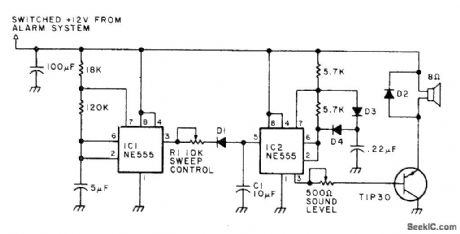
Generates force field of high-intensity sound inside car, painful enough to discourage thief from entering car after tripping alarm switch by opening door.Circuit produces square-wave output that sweeps up and down in frequency. Modulation is provided by triangle waveform generated by R1, D1, and C1. If sweep-frequency siren is prohibited, remove C1 to produce legal two-tone sound. Use efficient horn loudspeaker capable of handling up to 10W. D2 is silicon rectifier rated 1 A at 50 PIV. Other diodes are general-purpose silicon.-A. T. Roderick III, New Protection for Your Car, 73 Magazine, March 1978, p 76-77. (View)
View full Circuit Diagram | Comments | Reading(797)
Long_life_circuit_for_an_incandescent_lamp
Published:2009/7/21 22:26:00 Author:Jessie
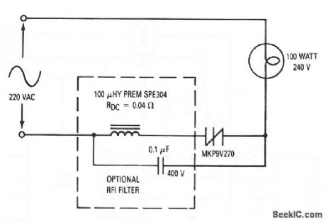
This circuit shows an MKP9V270 SIDAC used to phase-control anincandescent lamp,thus lowering the RMS voltage to the filament and prolongingthe life ofthe bulb,This is particularly useful when lamps are used In hard to reachlocations,such as In outdoor lighting In stgns where replacement costs are high. Bulb life span can be extended by 1.5 to 5 times,depending on the type of lamp,theamount of power reduction to the filament,and the number of times the lamp is switched on from a cold filament condition. Practical conduction angles runbetween 110°and 130°,with corresponding power reductions of 10%to 30%. (View)
View full Circuit Diagram | Comments | Reading(1213)
VHF_TRANSISTOR_AMPLIFIER_TESTER
Published:2009/7/21 22:26:00 Author:Jessie
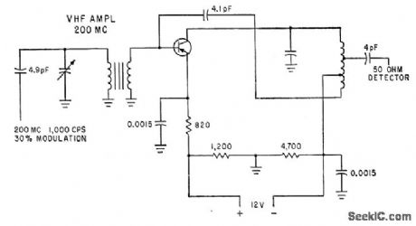
Has 6xed match, neutralization, and bias for use as standard test circuit for transistors in tv or vhf r-f amplifier stage. With 2N1742 transistor, power gain is 19 db, bandwidth up to 16 Mc, and maximum noise 5.5 db. -G. J. Flynn, Engineering Trends in Consumer Electronics, Electronics, 34:1, p 115-117. (View)
View full Circuit Diagram | Comments | Reading(776)
| Pages:999/2234 At 209819829839849859869879889899909919929939949959969979989991000Under 20 |
Circuit Categories
power supply circuit
Amplifier Circuit
Basic Circuit
LED and Light Circuit
Sensor Circuit
Signal Processing
Electrical Equipment Circuit
Control Circuit
Remote Control Circuit
A/D-D/A Converter Circuit
Audio Circuit
Measuring and Test Circuit
Communication Circuit
Computer-Related Circuit
555 Circuit
Automotive Circuit
Repairing Circuit