
Circuit Diagram
Index 980
TV_color_IF_amplifier_and_detector
Published:2009/7/21 8:56:00 Author:Jessie
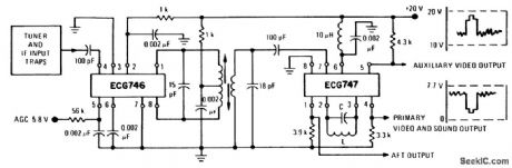
TV color IF amplifier and detector. This configuration will provide approximately 84 dB voltage gain. The nominal 3-volt peak-to-peak output can be varied between 0 and 7 volts with excellent linearity and freedom from spurious output products. Alignment is most easily accomplished with an AM generator set at a carrier frequency of 45.75 MHz, modulated with a video frequency sweep. The detector tank is first adjusted for maximum detected DC witlra CW input. Next the video sweep modulation is applied in order to align the input and interstage circuits (courtesy GTE Sylvania Incorporated). (View)
View full Circuit Diagram | Comments | Reading(872)
TV_video_IF_amplifier_with_low_level_detector
Published:2009/7/21 8:55:00 Author:Jessie
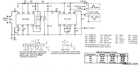
TV video IF amplifier with low-level detector (courtesy Motorola Semiconductor Products Inc.). (View)
View full Circuit Diagram | Comments | Reading(1878)
12_VDC_TO_117_VAC_AT_60_Hz_POWER_INVERTER
Published:2009/7/7 9:32:00 Author:May

Capacitor C5 and potentiometer R12 determine the frequency of the output signal at pin 3 of IC1, the 555 oscillator. The output signal is differentiated by C3 and C4 before it's input to the base of power tran-sistors Q1 and Q2 via diodes Dl and D2, respectively. The signal from IC1 is adjusted to 120 Hz, because the f[ip-flop formed by transistors Q3 and Q4 divides the frequency by 2.When Q3 is on, the base of Q1 is connected via RI to the regulated 12-V supply. Then, when the flip-flop changes states, Q4 is turned on and the base of Q2 connected to the 12-V supply through R2. The 100 mA base current allows Q1 and Q2 to alternately conduct through their respective halves to the transform-er's secondary winding.To eliminate switching transients caused by the rapid switching of Q3 and Q4, capacitors C1 and C2 filter the inputs to the base of Q1 and Q2 respectively. Power for the unit comes from an automobile's 12-V system or from a storage battery. The power is regulated by IC2, a 7812 regulator. LED1, connected across the 12-V input, can be used to indicate whether power is being fed to the circuit. The neon pilot lamp, LMP1, shows a presence or absence of output power. (View)
View full Circuit Diagram | Comments | Reading(840)
TV_video_IF_amplifier_with_detector_stage
Published:2009/7/21 8:53:00 Author:Jessie
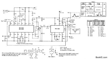
TV video IF amplifier with detector stage (courtesy Motorola Semiconductor Products Inc.). (View)
View full Circuit Diagram | Comments | Reading(1067)
TV_VHF_tuner_using_dual_gate_MOSFETs
Published:2009/7/21 8:52:00 Author:Jessie
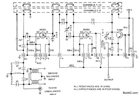
TV VHF tuner using dual-gate MOSFETs (courtesy Texas Instruments Incorpo rated). (View)
View full Circuit Diagram | Comments | Reading(1504)
Dual_4_bit_storage_register
Published:2009/7/21 8:52:00 Author:Jessie
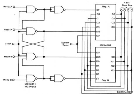
Dual 4-bit storage register (courtesy Motorola Semiconductor Products Inc.). (View)
View full Circuit Diagram | Comments | Reading(2113)
3_1_2_digit_parallel_data_acquisition_system_using_the_8052_7101_A_D_pair
Published:2009/7/21 8:50:00 Author:Jessie
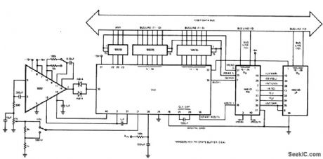
31/2-digit parallel data acquisition system using the 8052/7101 A/D pair (courtesy Intersil, Inc.). (View)
View full Circuit Diagram | Comments | Reading(845)
AFT_circuit_for_TV_with_detailed_coil_winding_data
Published:2009/7/21 8:50:00 Author:Jessie

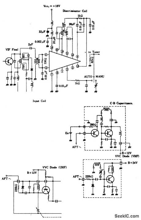
AFT circuit for TV with detailed coil winding data (courtesy GTE Sylvania Incor porated).
(View)
View full Circuit Diagram | Comments | Reading(880)
TV_AFT_AFC_circuit_for_three_types_of_systems_using_an_ECG1046_14_pin_DIP
Published:2009/7/21 8:48:00 Author:Jessie
TV AFT/AFC circuit for three types of systems using an ECG1046 14-pin DIP. The ECG1046 contains two VIF differential amplifiers, a phase detector, and a DC amplifier, whose output is supplied to a varactor diode in a tuner. It has the additional feature of having an internal regulated voltage supply. Partial tuner circuits shown are only for example applications. Coils and transformers should be selected to match the IF and can be obtained from discarded TV receivers or purchased at a local electronics parts jobber (Merit or Miller components). Maximum supply voltage for the ECG1046 is 20 volts (courtesy GTE Sylvania Incorporated). (View)
View full Circuit Diagram | Comments | Reading(825)
Complete_TV_video_IF_amplifier_and_detector_system
Published:2009/7/21 8:45:00 Author:Jessie
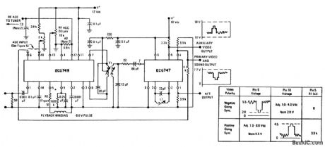
Complete TV video IF amplifier and detector system. The ECG749 contains two lF amplifiers, an AGC keyer, and an AGC amplifier; The circuit will work for both color and B&W. See table for AGC information (courtesy GTE Sylvania Incorporated). (View)
View full Circuit Diagram | Comments | Reading(771)
Electrono_tuner_contror_memory_for_radio_and_TV
Published:2009/7/21 8:43:00 Author:Jessie
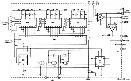
Electrono tuner contror/memory for radio and TV. The SH1549 gives capability of storing and recalling up to 16stations in addition to conventional varactor tuning. The SH 1549 converts the analog tuning voltage into a 12-bit digital word and stores it in memory for future use (courtesy Fairchild Semiconductor). (View)
View full Circuit Diagram | Comments | Reading(835)
CMOS__keyboard_data_entry_system
Published:2009/7/21 8:43:00 Author:Jessie

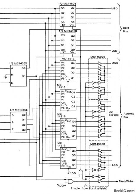

CMOS keyboard data entry system (courtesy Motorola Semiconductor Products Inc.). (View)
View full Circuit Diagram | Comments | Reading(2250)
8_bit_binary_to_3_digit_decimal_display_decoder_for_8_bit_microprocessor_systems_with_256_by_4_PROM_three_7_segment_decoder_drivers_with_9374_input_latches_and_two_gates
Published:2009/7/21 8:39:00 Author:Jessie
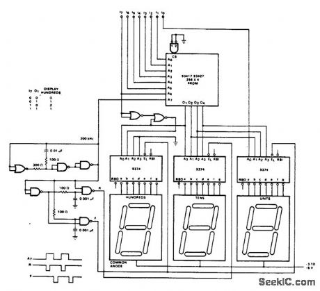
8-bit binary to 3-digit decimal display decoder for 8-bit microprocessor systems with 256 by 4 PROM, three 7-segment decoder/drivers with 9374 input latches and two gates (courtesy Fairchild Semiconductor). (View)
View full Circuit Diagram | Comments | Reading(9596)
Synchronizing_two_M6802_microprocessors_on_one_bus
Published:2009/7/21 8:37:00 Author:Jessie
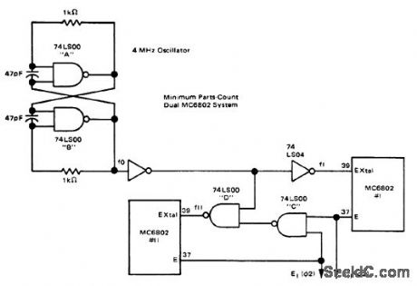
Synchronizig two M6802 microprocessors on one bus (courtesy Motorola Semiconductor Products Inc.). (View)
View full Circuit Diagram | Comments | Reading(1042)
ColorTV_horizontal_self_regulating_scan_circuitry_fora_19_inch_receiver
Published:2009/7/21 8:33:00 Author:Jessie

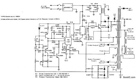
ColorTV horizontal self-regulating scan circuitry fora 19-inch receiver (courtesy Motorola Semiconductor Products Inc.).
(View)
View full Circuit Diagram | Comments | Reading(821)
Eight_channel_data_acquisition_circuit_for_the_M6800
Published:2009/7/21 8:32:00 Author:Jessie
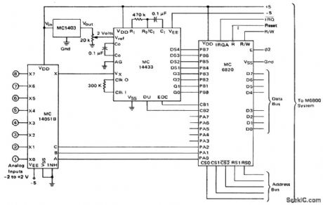
Eight-channel data acquisition circuit for the M6800 (courtesy Motorola Semiconductor Products Inc.). (View)
View full Circuit Diagram | Comments | Reading(1502)
_Color_TV_chroma_processor_using_an_ECG1089_20_pin_DIP
Published:2009/7/21 7:51:00 Author:Jessie
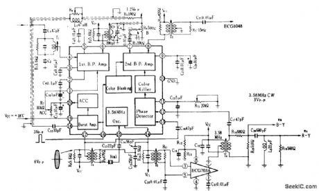
Color TV chroma processor using an ECG1089 20-pin DIP. The ECG1048 noted on the schematic is a chroma demodulator The ECG703A is a 3.58 MHz amplifier(courtesy GTE Sylvania Incorporated) (View)
View full Circuit Diagram | Comments | Reading(929)
40_W_AT_50_MC
Published:2009/7/21 7:50:00 Author:Jessie

Can be used with phase-modulated oscillator as drive source or with crystal oscillator for straight cw operation. Grounded emitter tonus m driver Q3 and power amplifier should be as short as possible to prevent degeneration.-R. Brubaker, A Solid-State Transmitter with 40 Watts Output at 50 MHz, Motorola Application Note AN-172, Dec. 1965. (View)
View full Circuit Diagram | Comments | Reading(854)
Low_voltage_controlled_triac_switch
Published:2009/7/21 7:50:00 Author:Jessie
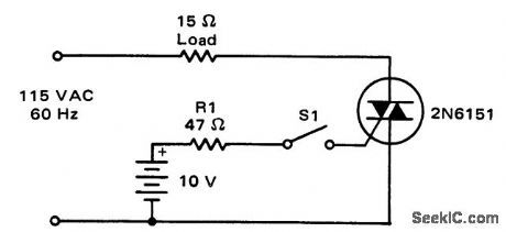
Low-voltage-controlled triac switch (courtesy Motorola Semiconductor Products Inc.). (View)
View full Circuit Diagram | Comments | Reading(819)
PHASE_SHIFT_KEYER
Published:2009/7/21 7:49:00 Author:Jessie
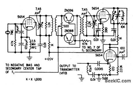
Used with double-side-band suppressed-carrier modulation. Crystal-controlled Colpitts oscillator drives transistor gate, which in turn feeds conventional tuned pentode r-f amplifier and tuned cathode follower.-J. Dysinger, W. Wyland, and It Wood, New Suppressed-Carrier Modulation Technique, Electronics, 33:6, p 47-49. (View)
View full Circuit Diagram | Comments | Reading(1062)
| Pages:980/2234 At 20961962963964965966967968969970971972973974975976977978979980Under 20 |
Circuit Categories
power supply circuit
Amplifier Circuit
Basic Circuit
LED and Light Circuit
Sensor Circuit
Signal Processing
Electrical Equipment Circuit
Control Circuit
Remote Control Circuit
A/D-D/A Converter Circuit
Audio Circuit
Measuring and Test Circuit
Communication Circuit
Computer-Related Circuit
555 Circuit
Automotive Circuit
Repairing Circuit