
Circuit Diagram
Index 963
MOS_to_AC_load_interface_using_an_MOC3011_optically_coupled_triac_driver
Published:2009/7/21 6:08:00 Author:Jessie
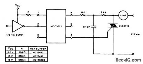
MOS to AC load interface using an MOC3011 optically coupled triac driver (courtesy Motorola Semiconductor Products Inc.). (View)
View full Circuit Diagram | Comments | Reading(1882)
DIGITAL_TOUCH_ON_OFF_SWITCH
Published:2009/7/8 3:41:00 Author:May
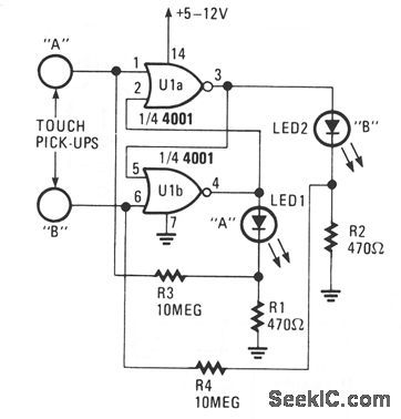
Only one LED can be on when the circuit is at rest. Which LED is illuminated is determined by the touch pick-up that last had human contact. Pickup terminal A controls the on condition of LED1, and terminal B controls the on condition of LED2. A 4001 quad two-input NOR gate is connected in an anti-bounce latching circuit that is activated by touching a pickup. (View)
View full Circuit Diagram | Comments | Reading(1047)
FET_PNP_BOOTSTRAPPED_SOURCE_FOLLOWER_
Published:2009/7/21 6:07:00 Author:Jessie
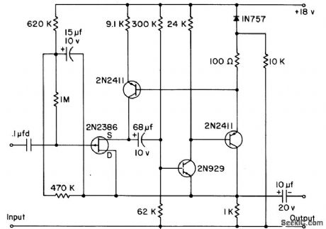
Drain and gate divider are bootstrapped in phase with source, to reduce input capacitance of fet to minimum so only real part of input impedance is seen at high frequencies, in unity-gain high-input-impedance wideband preamplifier. Low-frequency input impedance is 100 meg. Frequency response is within 3 db up to 10 Mc for 50-ohm generator resistance, to 1 Mc for 100,000 ohms, and to 0.1 Mc for 1 meg.-Texas Instruments Inc., Solid-State Communications, McGraw-Hill, N.Y., 1966, p 138. (View)
View full Circuit Diagram | Comments | Reading(1552)
455_kHz_IF_WITH_AF_COMPRESSOR
Published:2009/7/8 3:41:00 Author:May

Combination of IF amplifier, audio compressor, tunable audio filter, and audio output system operates from single supply. Compressor and filter each use N5558V dual opamps or equivalent units. Tuning range of filter is about 500 to 2000 Hz. IF input goes directly to pin 2 of LM373H.Use coupling capacitor to prevent shorting pin 2 to ground and damaging IC.-R. Megirian, Design ldeasfor Miniature Communications Receivers, Ham Radio, April 1976, p 18-25. (View)
View full Circuit Diagram | Comments | Reading(889)
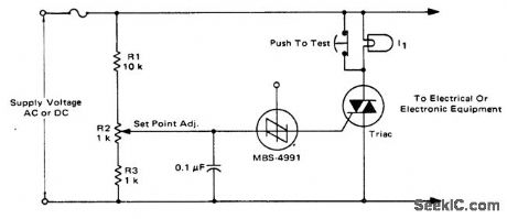
High_intensity_lamp_dimmer_or_fan_control
Published:2009/7/21 6:06:00 Author:Jessie
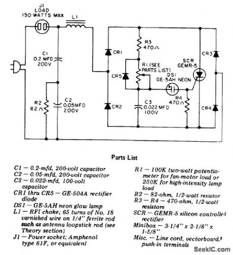
High-intensity lamp dimmer or fan control. This circuit is for use with high-intensity lamps with a built-in transformer only; do not use with 120-volt standard household incandescent or fluorescent lamps. Fan motors should not draw more than 1.5 amperes (courtesy General Electric Company). (View)
View full Circuit Diagram | Comments | Reading(2334)
Electronic_crowbar_circuit_using_an_SBS_and_a_triac
Published:2009/7/21 6:03:00 Author:Jessie
Electronic crowbar circuit using an SBS and a triac. This circuit protects equipment by placing a short-circuit across the line, thereby blowing the fuse. It works on DC circuits as well as AC types since the SBS and triac are both bilateral devices (courtesy Motorola Semiconductor Products Inc.). (View)
View full Circuit Diagram | Comments | Reading(2188)
SOR_full_range_power_controller_incorporating_an_SUS
Published:2009/7/21 6:02:00 Author:Jessie
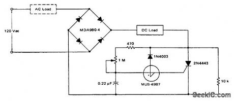
SOR full-range power controller incorporating an SUS (courtesy Motorola Semiconductor Products Inc.). (View)
View full Circuit Diagram | Comments | Reading(667)
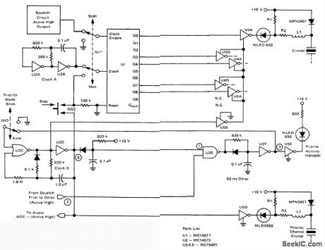
10_channel_with_thumbwheel_program_mable_priority_logic_for_scanner_monitor_receiver
Published:2009/7/21 6:02:00 Author:Jessie
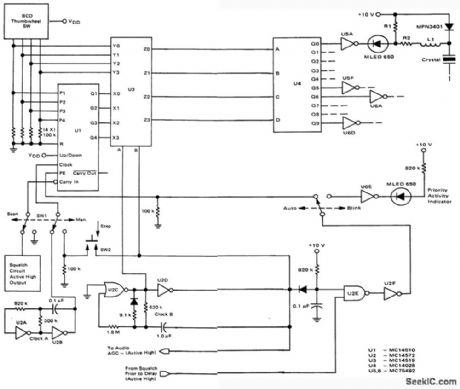
10-channel with thumbwheel-program mable-priority logic for scanner/monitor receiver (courtesy Motorola Semiconductor Products Inc.). (View)
View full Circuit Diagram | Comments | Reading(1131)
POSITIVE_TRIGGERED_TOUCH_CIRCUIT
Published:2009/7/8 3:38:00 Author:May
LED1 and LED2 indicators turn on and remain on, each time the circuit is triggered. During the timing cycle, U1's Q output at pin 11 becomes positive when the Q output at pin 11 becomes negative. The two LEDs can be removed and the Q and Q outputs at pins 10 and 11, respectively, can be used to trigger some other circuit. (View)
View full Circuit Diagram | Comments | Reading(749)
455_kHz_CASCODE_IF
Published:2009/7/8 3:35:00 Author:May
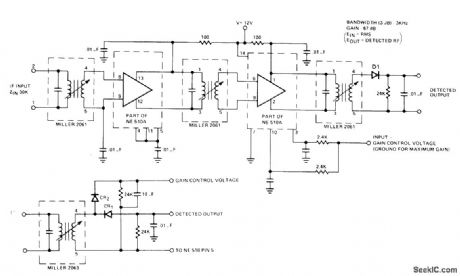
Sections of Signetics NE510A transistor array serve as active elements for IF strip using standard transformers.Voltage gain is 66 dB when gain-control input is grounded. Altemate detector connection for including AGC is shown below.- Signetics Analog Data Manual, Signetics, Sunnyvale, CA, 1977, p 746-747. (View)
View full Circuit Diagram | Comments | Reading(1053)
Feedback_control_circuit_to_trigger_a_thyrister
Published:2009/7/21 6:01:00 Author:Jessie
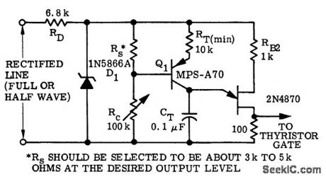
Feedback control circuit to trigger a thyrister (courtesy Motorola Semiconductor Products Inc.). (View)
View full Circuit Diagram | Comments | Reading(708)
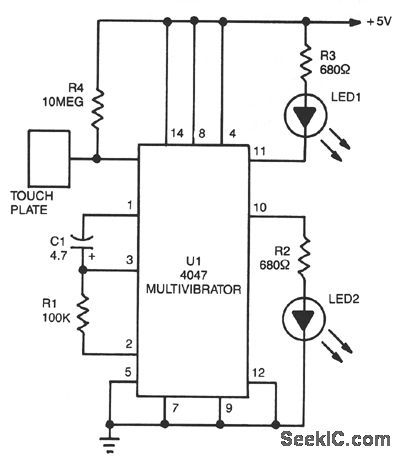
NEGATIVE_TRIGGERED_TOUCH_CIRCUIT
Published:2009/7/8 3:32:00 Author:May
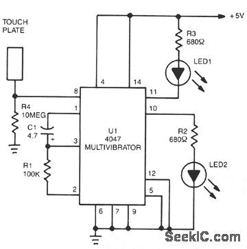
The 4047 is configured as a monostable multivibrator circuit or one shot that is set up to trigger on a negative-transition of the signal applied to its pin 6 input. The multi ibrator's on time is determined by the values of R1 and C1. Although R1 is shown to be a 100-K unit, its value can be anything between 10 K and 1 MΩ . Capacitor C1 can be a nonpolarized capacitor with any practical value above 100 pF. By making R4's value extremely high, the circuit can be used as a touch-triggered one-shot multivibrator. If the value of R4 is reduced to a much lower value, such as 10 KΩ , the circuit can be triggered with a negative pulse through 0.1-μF capacitor connected to pin 6. With a 100-K Ω resistor for R1, and a 4.7-μF electrolytic capacitor for C1, the circuit's on time is about 0.6 second. When R1 is increased to 470 K Ω, the on time of the circuit is increased to over 6 seconds. (View)
View full Circuit Diagram | Comments | Reading(1488)
60_MHz_WITH_80_dB_POWER_GAIN
Published:2009/7/8 3:32:00 Author:May
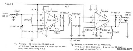
T-stage tuned IF ampIifier achIeves maximum gain and output signal swing capability by using differential-mode coupling for interstage and output network Overall bandwidth is 1.5 MHz Resistors in series with AGC pins 2 of opamp stages provide more efficient AGC action,-B.Trout,''A High Gain Integrated Circuit RF-IF Amplifier with Wide Range AGC.''Motorola,Phoenix,AZ.1975,an-513,p 8. (View)
View full Circuit Diagram | Comments | Reading(702)
Regulated_DC_motor_control_with_feedback_from_optical_sensor
Published:2009/7/21 5:59:00 Author:Jessie
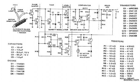
Regulated DC motor control with feedback from optical sensor (courtesy Motorola Semiconductor Products Inc.).
(View)
View full Circuit Diagram | Comments | Reading(983)
7_KV_AND_450_V_OSCILLATOR_TYPE_CRT_SUPPLY
Published:2009/7/21 5:58:00 Author:Jessie
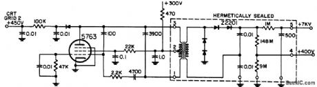
Pentode audio oscillator feeds hermetically sealed transformer-rectifter-filter unit.-NBS, Handbook Preferred Circuits Navy Aeronautical Electronic Equipment, Vol. 1, Electron tube Circuits, 1963, p N14-4. (View)
View full Circuit Diagram | Comments | Reading(591)
001°C_CONTROL_WITH_OPAMP_COMPABA_TOR
Published:2009/7/8 3:27:00 Author:May
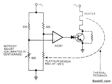
Uses platinum sensor in bridge configuration, with opamp connected across bridge differentially. When cold, sensor resistance is Iess than 500 ohms so opamp saturates to give positive output that tums on power transistor and heater. As oven warms, sensor resistance increases, brklge balance shifts, and heater is cut off.-J. Williams, Designer's Guide to: Temperature Control, EDNMagazine, June 20, 1977, p 87-95.
(View)
View full Circuit Diagram | Comments | Reading(627)
RUMBLE_SCRATCH_FILTER
Published:2009/7/8 3:26:00 Author:May
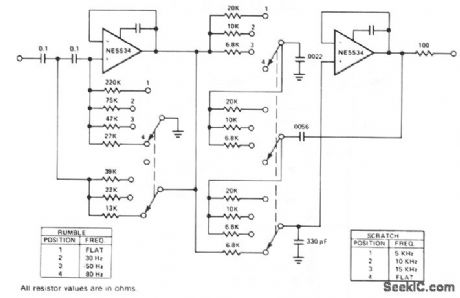
This is a variable bandpass amplifier with adjustable low- and high-frequency cutoffs. (View)
View full Circuit Diagram | Comments | Reading(0)
CRYSTAL_OVEN
Published:2009/7/8 3:26:00 Author:May
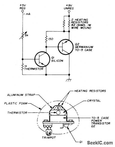
All components for pioportional temperature control circuit are mounted on crystal, so total power of 2 W maximum serves for maintaining crystal temperature.Thermistor is about 1K at room emperature.Transistor types are not critical butshould have low leakage currents. Thermistor current of about 1-mA should be much more than O.1-mA base current of Q1. If Q2 is silicon, increase 150-on resistor to 680 ohms.-P. H. Mathieson, Simple Crystal Oven, Ham Radio, April1976, p 66. (View)
View full Circuit Diagram | Comments | Reading(1396)
9_channel_plus_fixed_priority_cha_nnel_logic_for_PF_scanner_monitor_receiver
Published:2009/7/21 5:58:00 Author:Jessie
9-channel plus fixed-priority-cha nnel logic for PF scanner/monitor receiver (courtesy Motorola Semiconductor Products Inc.). (View)
View full Circuit Diagram | Comments | Reading(739)
WIEN_BRIDGE_FILTER
Published:2009/7/8 3:24:00 Author:May
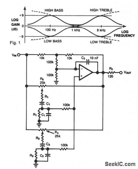


Most audio tone controls affect midband gain, and they often create booming or hissing sounds when activated. You can avoid these problems by using a dual Wien-bridge filter to provide independent control of the treble and bass frequencies.Experiments with equalizers indicate that the optimum center frequencies are about 100 Hz and 8 kHz. Using the relationf = (2πRC)-1, set the Fig. 1 values accordingly:
100 Hz: R1 = 15 KΩ; C1 = 0.1 μF 8 kHz: R2 = 16 KΩ; C2 = 1.3 μFR3 and C3 provide stability. You obtain a ± 9 dB variation of treble and bass by adjusting potentiometers R4 and R5, respectively. The filter's frequency response is shown in Fig. 2. (View)
View full Circuit Diagram | Comments | Reading(1783)
| Pages:963/2234 At 20961962963964965966967968969970971972973974975976977978979980Under 20 |
Circuit Categories
power supply circuit
Amplifier Circuit
Basic Circuit
LED and Light Circuit
Sensor Circuit
Signal Processing
Electrical Equipment Circuit
Control Circuit
Remote Control Circuit
A/D-D/A Converter Circuit
Audio Circuit
Measuring and Test Circuit
Communication Circuit
Computer-Related Circuit
555 Circuit
Automotive Circuit
Repairing Circuit