
Circuit Diagram
Index 972
PROPORTIONING_CONTROLLER
Published:2009/7/7 22:50:00 Author:May
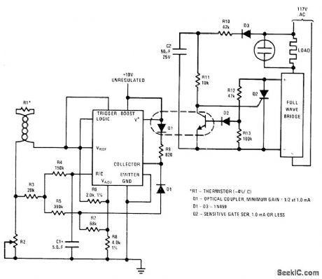
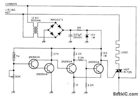
National LM122 timer is used as proportioning temperature controller with optical isolation and synchronized zero-crossing. R2 is used to set tem-perature to be controlled by thermistor R1. SCR used for Q2 is chosen to handle required load.D3 is rated at 200 V. R12, R13, and D2 implement synchronized zero-crossing feature.-C. Nelson, Versatile Timer Operates from Microseconds to Hours, National S_emiconductor, Santa Clara, CA, 1973, AN-97, p 8.
(View)
View full Circuit Diagram | Comments | Reading(741)
WIRELESS_TELEPHONE_EAVESDROPPER
Published:2009/7/7 22:49:00 Author:May
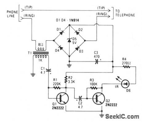
The IR transmitter connects to a telephone circuit, and transmits both sides of all telephone conversations to any line-of-sight location, within 40 feet. No power is taken from the central office, as long as all phones remain on-hook. The current flows through the phone and back to the central offtce, thereby keying their equipment. We tap into the telephone line by connecting the IR transmitter circuit in series with either the tip or ring. When the telephone is off-hook, current will flow through the diode bridge polarity protector and supply the power for the IR transmitter. The phone's audio information is taken off the line by transformer T1. The 1000-Ω winding of the transformer connects to a two-stage transistor audio amplifier/modulator. A 2000-Ω potentiometer could be added to the input of the two-stage amplifter to control the modulation level, and another potentiometer could be added in place of R3 to adjust the IR's idle current. (View)
View full Circuit Diagram | Comments | Reading(1000)
Triac_control_circuit_with_current_boost_using_an_ECG776_zero_voltage_switch
Published:2009/7/21 7:27:00 Author:Jessie
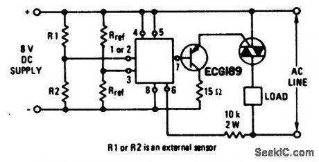
Triac control circuit with current boost using an ECG776 zero voltage switch. Resistor R2 must be the external sensor for the internal short and open protection to be operative. Notice that the circuit utilizes a DC supply. Select the triac for the particular application from the ECG5600 series (courtesy GTE Sylvania Incorporated). (View)
View full Circuit Diagram | Comments | Reading(1470)
APPROXIMATING_VECTOR_SUMS
Published:2009/7/7 22:48:00 Author:May
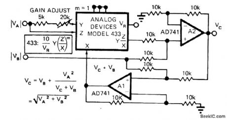
Combination of two opamps and Analog Devices 433 multiplier1divider IC provides output voltage equal to vector sum of two input voltages, by computing square root of sum of squares.-D.H. Sheingold, Approximate Analog Functions with a Low-Cost Multiplier/Divider, EDN Magazine, Feb. 5, 1973, p 50-52. (View)
View full Circuit Diagram | Comments | Reading(751)
COOKER_CONTROL
Published:2009/7/7 22:48:00 Author:May
Uses Model K600A thermistor (Allied Electronics) placed in slow cooker to maintain ideal cooking temperature. Pot can be adjusted to provide triggering for ON/OFF control of heating element for cooker, Use polarized power plug for proper operation.-Circuits, 73Magazine, May 1977, p 19. (View)
View full Circuit Diagram | Comments | Reading(1272)
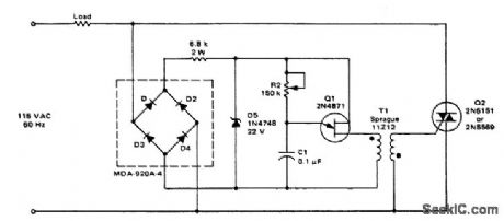
RING_DETECTOR
Published:2009/7/7 22:45:00 Author:May
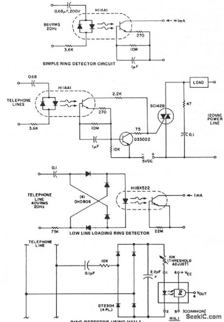
This circuit detects the 20 Hz, ≈ 86-V rms ring signal on telephone lines and initiates action in an electrically isolated circuit. Typical applications would include automatic answering equipment, and interconnect/interface and key systems. The circuits illustrated are bare bones circuits designed to illustrate concepts. They might not eliminate the ac/dc ring differentiation, 60-Hz noise rejection, dial tap rejection, and other effects that must be considered in field application. The first ring detector is the simplest and provides about 1-mA signal for a 7-mA line loading for 1/10 sec after the start of the ring signal. The time delay capacitor provides a degree of dial tap and click suppression, as well as filtering out the zero crossing of the 20-Hz wave. This circuit provides the basis for a simple example, a ring extender that operates lamps and buzzers from the 120-V, 60-Hz power line, while maintaining positive isolation between the telephone line and the power line. Use of the isolated tab triac simplifies heat sinking by removing the constraint of isolating the triac heatsink from the chassis. Lower line current loading is required in many ring detector applications. This can be provided by using the H11BX522 photo-Darlington optocoupler, which is specified to provide a 1-mA output from a 0.5-mA input through the -25°C to +50°C temperature range.°The next circuit allows ring detection down to a 40-V rms ring signal while providing 60-Hz rejection to about 20-V rms. Zero-crossing filtering can be accomplished either at the input bridge rectifier or at the output. Dependable ring detection demands that the circuit responds only to ring signals, rejecting spurious noise of similar amplitude, such as dialing transients. The configuration shown relies on the fact that ring signals are composed of continuous frequency bursts, whereas dialing transients are much lower in repetition rate. The dc bridge-filter combination at the H11L input has a time constant; it cannot react to widely spaced dialing transients, but will detect the presence of relatively long duration bursts, causing the H11L to activate the downstream interconnect circuits at a precisely defined threshold. (View)
View full Circuit Diagram | Comments | Reading(0)
FOUR_QUADRANT_WITHOUT_LEVEL_SHIFT
Published:2009/7/7 22:45:00 Author:May
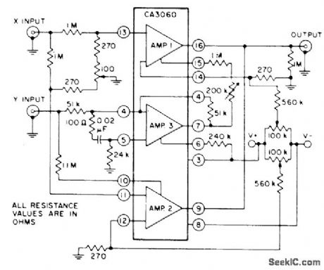
CA3060 three-opamp array provides four-quad-rant multiplication without level shift between input and output. Circuit includes adjustments associated with differential input and adjustment for equalizing gains of amplifiers 1 and 2.Amplifier 3 is connected as unity-gain inverter- Linear Integrated Circuits and M0S/FET's, RCA Solid State Division, Somerville, NJ, 1977, p 153. (View)
View full Circuit Diagram | Comments | Reading(759)
FOUR_QUADRANT_MULTIPLYING_DAC
Published:2009/7/7 22:41:00 Author:May
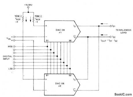
Combination of two Precision Monolithics DAC-08 D/A conveners accepts differential input voltage and produces differential current output, 0ut-put opamp is not normally required. Output analog polarity is controlled by analog input ref-erence or by offset-binary digital input word. Common-mode current present at output must be accommodated by balanced load. Differential input range is 10 V.-J. Schoeff and D. Soderquist, Differential and Multiplying Digital to Analog Converter Applications, Precision Monolithics, Santa Clara, CA, 1976, AN-19, p 3. (View)
View full Circuit Diagram | Comments | Reading(1244)
460_KC_F_M_WIRELESS_MICROPHONE
Published:2009/7/21 7:27:00 Author:Jessie
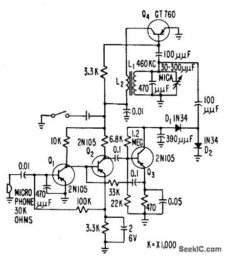
Radiates about 0.2 micromicrowatt directly from tank circuit to establish induction field within usable area of auditorium stage without exceeding FCC radiation field limitation. Normal speaking voice produces peak f-m deviation of about 10 kc.-G. F. Montgomery, Wireless Microphone Uses F-M Modulation, Electronics, 31:1, p 54-55. (View)
View full Circuit Diagram | Comments | Reading(1125)
TWO_QUADRANT
Published:2009/7/7 22:39:00 Author:May
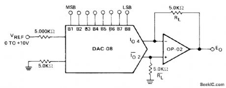
Bipolar digital multiplier has output polarity controlled by offset-binary-coded digital input word. Precision Monolithics DAC-08 D/A converter drives OP-02 opamp. 0utput is symmetrical about ground.-J. Schoeff and D. Soderquist, Differential and Multiplying Digital to Analog Converter Applications, Precision Monolithics, Santa Clara, CA, 1976, AN-19,p2. (View)
View full Circuit Diagram | Comments | Reading(2836)
PHASE_SENSITIVE_DETECTOR
Published:2009/7/7 22:36:00 Author:May
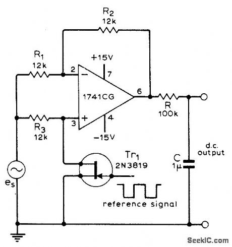
Circuit using single opamp produces DC output proportional to both amplitude of AC input signal and cosine of its phase angle relative to reference signal.Can be used as synchronous rectifier in chop-per-type DC amplifier or for accurate measurement of small AC signals obscured by noise. Article gives design equations.-G. B. Clayton, Experiments with Operational Amplifiers, Wire-less World, July 1973, p 355-356. (View)
View full Circuit Diagram | Comments | Reading(0)
800_watt_soft_start_triac_light_dimmer
Published:2009/7/21 7:26:00 Author:Jessie
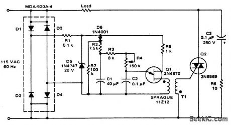
800-watt soft-start triac light dimmer (courtesy Motorola Semiconductor Products Inc.). (View)
View full Circuit Diagram | Comments | Reading(3910)
9_KC_OSCILLATOR_STABILIZER
Published:2009/7/21 7:25:00 Author:Jessie

Insures 24 w output over temperature range of -20 to +120°F. Zener diode voltage-regulating circuit prevents changes in collector supply voltage of oscillator Q1. Base-driven modulator Q2 may be fed from tape repeater preamp, microphone, or master control center serving induction radio system using roadside telephone-line loops.-E. A. Hanysz, J. E. Stevens, and A. Meduvsky, Communication System for Highway Traffic Control, Electronics, 33:42, p 81-83. (View)
View full Circuit Diagram | Comments | Reading(737)
APPROXIMATING_COSINES
Published:2009/7/7 22:34:00 Author:May
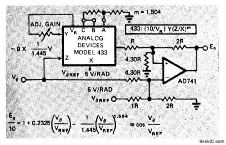
Analog Devices 433 multiplier/divider IC approximates cosine of angle to better than 1%, by computing nonintegral exponents. 0nly one opamp is needed. Approximation uses arbitrary exponent as one term of cosineθplus a linear term and a constant term, as described in article.-D. H. Sheingold, Approximate Analog Functions with a Low-Cost Multiplier/Divider, EDN Magazine, Feb. 5, 1973, p 50-52. (View)
View full Circuit Diagram | Comments | Reading(850)
800_watt_triac_light_dimmer
Published:2009/7/21 7:25:00 Author:Jessie
800-watt triac light dimmer (courtesy Motorola Semiconductor Products Inc.). (View)
View full Circuit Diagram | Comments | Reading(733)
CASSETTE_INTERFACE
Published:2009/7/7 22:32:00 Author:May
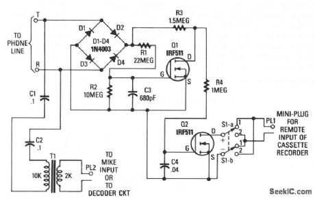
Q1 and Q2 are used to form the basis of an interface circuit for attaching a cassette recorder to the phone line. The circuit does not require a power supply because operating power is drawn from the telephone line itself. The incoming signal is fed across a bridge-rectifier circuit, consisting of diodes D1 through D4.When the phone is on hook, the voltage at the output of the bridge at the R1/R3 junction is near 48 V.That voltage is fed across a voltage divider consisting of R1 and R2. The voltage at the junction formed by R1 and R2 is fed to the gate of Q1, turning it on. That pulls the drain of Q1 low. Since the gate of Q2 is connected to the drain of Q1, the bias applied to the gate of Q2 is low, holding it in the OFF state.When the answering machine responds to a call or a phone is taken off hook, the voltage across the phone lines drops below 10 V, causing Q1 to turn off. At that point, the voltage at Q1's drain rises, turning Q2 on. The remote input of the cassette is connected to Q2's drain and source through S1, and a miniature plug is connected to the remote input jack.Switch S1 must be in a position so that the positive lead of the recorder's remote input connects, through switch position 1, to Q2's drain and the negative input to Q2's source. Switch S1 provides a convenient way to reverse the circuit's trigger output without having to unsolder and resolder leads. The phone's audio is coupled through C1, C2, and T1 to the microphone input of the cassette recorder. (View)
View full Circuit Diagram | Comments | Reading(2653)
STEREO_POWER_METER
Published:2009/7/7 22:32:00 Author:May
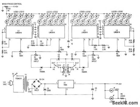
The Stereo Power Meter is made up of two identical circuits and a power supply. Each circuit contains two LM3914 display chips which contain 10 voltage comparators, a 10-step voltage divider, a referencevoltage source, and a mode-select circuit that selects a bar or dot display via a logic input at pin 9. The brightness of the LEDs is controlled by the 1900-Ω resistors and the reference voltage is controlled by the 3900-Ω resistors. The 10-step voltage divider within the chips is connected between the reference voltage and ground. Since each step of the voltage divider is separated by a 1-KΩ resistor, each comparator senses voltage 10% greater than the preceding comparator. The signal is applied to pin 5, which is buffered through a resistor-diode network and then amplified as it passes to each of the10 comparators. Each LED is arounded through the comparators as the input signal voltage matches the reference voltage. That results in one to 10 LEDs illuminating as the signal voltage increases. (View)
View full Circuit Diagram | Comments | Reading(2034)
TV45_MHz_sound_channel_with_1__wattAF_output_using_an_ECG1051_chipand_an_ECG171_bipolartransistor
Published:2009/7/21 7:24:00 Author:Jessie
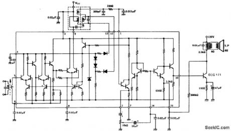
TV4.5 MHz sound channel with 1 -wattAF output using an ECG1051 chipand an ECG171 bipolartransistor. Typical supply voltage for the chip is 10 g volts, while the output transistor can be operated from a 120-volt DC supply. Audio output from the chip is 3 volts RMS. The IF transfomen radio detector transformer and audio output transfomer are all standard and can be purchased at Radio Shack(courtesy GTE Sylvania Incorporated).
(View)
View full Circuit Diagram | Comments | Reading(806)
3_IN_1_TEST_SET
Published:2009/7/7 22:30:00 Author:May
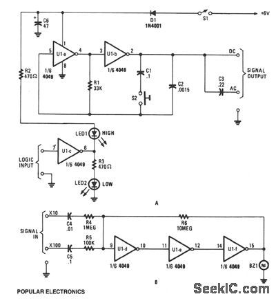
This circuit is designed around a 4049 hex inverter/buffer. Two inverters are used in a dual-frequency signal-injector circuit, another inverter is used as a logic probe, and the remaining three inverters are used as a sensitive dual-input, audio-signal tracer.The signal-injector potion gates are configured as a two-frequency, pulse-generator circuit. Under normal conditions, the generator's output frequency is around 10 kHz, but when S2 is closed, the output frequency drops to about 100 Hz. The logic-probe potion is made up of U1c, the output of the inverter decreases. The low output of U1c reverse biases LED2, so it remains off. That low output also forward biases LED1, causing it to light. But when a logic low presented Ulc's input, the situation is reversed, so LED2 lights and LED1 darkens.The audio-signal tracer portion is made up of the three remaining inverters which are configured as a linear audio amplifier to increase the input signal level by a factor of 10 or 100. The amplified output signal feeds a miniature piezo element of audible detection.
(View)
View full Circuit Diagram | Comments | Reading(1715)
FOUR_QUADRANT_WITH_OPAMP_LEVEL_SHIFT
Published:2009/7/7 22:29:00 Author:May
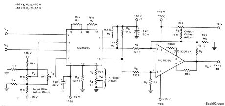
Connections shown for Motorola MC1595L linear four-quadrant multiplier are used in applications requiring level shift to ground reference. Common-mode voltage is reduced by 10:1 attenuation networks, and differential output voltage is fed to opamp having closed-loop gain of 10. Resulting output is stillVxVy/10, which appears single-ended above ground reference. Each input can be between-10 V and +10 V. Frequency limit of circuit is about50 kHz for signal swings approaching ±10 V.-E. Renschler, Analysis and Basic Operation of the MC1595, Motorola, Phoenix. AZ, 1975, AN-489 p 9. (View)
View full Circuit Diagram | Comments | Reading(1006)
| Pages:972/2234 At 20961962963964965966967968969970971972973974975976977978979980Under 20 |
Circuit Categories
power supply circuit
Amplifier Circuit
Basic Circuit
LED and Light Circuit
Sensor Circuit
Signal Processing
Electrical Equipment Circuit
Control Circuit
Remote Control Circuit
A/D-D/A Converter Circuit
Audio Circuit
Measuring and Test Circuit
Communication Circuit
Computer-Related Circuit
555 Circuit
Automotive Circuit
Repairing Circuit