
Circuit Diagram
Index 967
THREE_CHIP_EKG_SIMULATOR
Published:2009/7/8 2:06:00 Author:May
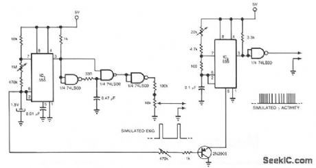
Two 555s and a quad NAND-gate IC can simulate an electrocardiograph signal and a γ-wave radioisotope signal for applications in nuclear medicine. This circuit synchronizes the radioisotope signal to the EKG signal. You can use the circuit's outputs to test, for example, microprocessor-based software that calculates the left ventricular ejection fraction before you use the software in clinical applications. IC1, a 555 timer, provides a positive-going pulse train that simulates an EKG signal. A 10-KΩ potentiometer provides frequency adjustment. The other 555 timer, configured as a pulse-position modulator, provides the simulated γ-wave activity. (View)
View full Circuit Diagram | Comments | Reading(1186)
THERMOMETER_ADAPTER
Published:2009/7/8 2:04:00 Author:May
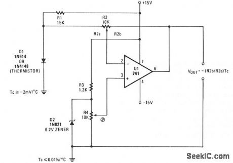
A simple op amp and silicon diode are the heart of the temperature-to-voltage converter that will permit you to use an ordinary voltmeter-either analog or digital-to measure temperature. User adjustments make it possible for a reading of either 10 mV or 100 mV to represent 1°F or C.
Temperature sensor D1 is a 1N4148 silicon diode. It has a temperature coefficient of -2 mV/°C. U1, a 741 op amp, is connected as a differential amplifier. A voltage divider consisting of R3 and Zener diode D2 provides a 6.2 V reference voltage. D2 is shunted by potentiometer R4, so that the offset can be adjusted to align the output voltage with either the Celsius or Fahrenheit scale, as desired.
Gain control R2 is adjusted so the output of the op amp is in the scale or voltage range of the meter being used. R4, the offset adjust control, is then adjusted so the output voltage represents either degrees F or C. The thermometer adapter can be calibrated by adjusting R4 while the probe sensor is at a known temperature. (View)
View full Circuit Diagram | Comments | Reading(2334)
PEAK_dB_METER
Published:2009/7/8 2:02:00 Author:May

This circuit compares a rectified input,VNN, with a voltage that decays exponentially across a 4.7-kΩ resistor and a 0.01-μF capacitor.Comparing the exponentially decaying voltage with the rectified input provides a peak-level indication that requires no adjustment.A phaes-locked loop controls the scan rate so that each LED represents 6 dB in the 30 dB range. (View)
View full Circuit Diagram | Comments | Reading(924)
OPTICAL_PICK_UP_TACHOMETER
Published:2009/7/8 2:00:00 Author:May
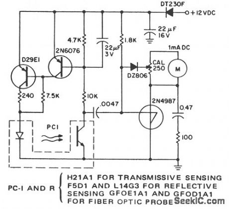
Remote, noncontact, measurement of the speed of rotating objects is the purpose of this simple circuit. Linearity and accuracy are extremely high and normally limited by the milliammeter used and the initial calibration. This circuit is configured to count the leading edge of light pulses and to ignore normal ambient light levels. It is designed for portable operation since the tachometer is not sensitive to supply voltage within the supply voltage tolerance. Full scale at the maximum sensitivity of the calibration resistance is read at about 300 light pulses per second. A digital voltmeter can be used, on the 100-mV full-scale range, in place of the milliammeter. Shunt its input with a 100-Ω resistor in parallel with a 100-μF capacitor. This rc network replaces the filtering supplied by the analog meter.
(View)
View full Circuit Diagram | Comments | Reading(1062)
SIMPLE_LINEAR_THERMOMETER
Published:2009/7/8 1:59:00 Author:May
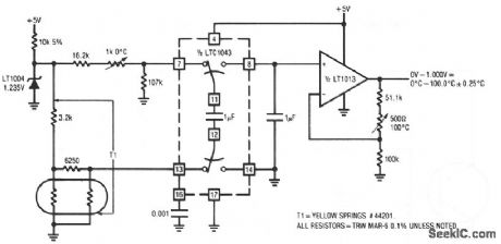
The thermistor network specified eliminates the need for a linearity trim-at the expense of accuracy and operational range. (View)
View full Circuit Diagram | Comments | Reading(598)
LED_PANEL_METER
Published:2009/7/8 1:59:00 Author:May
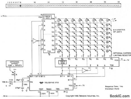
View full Circuit Diagram | Comments | Reading(1961)
Color_TV_automatic_resolution_control_1
Published:2009/7/21 7:44:00 Author:Jessie
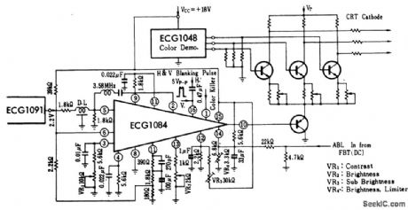
Color TV automatic resolution control. The ECG1091 partially shown is for reference only and is a videp processor chip (courtesy GTE Sylvania Incorporated). (View)
View full Circuit Diagram | Comments | Reading(690)
ROOM_HEATER_CONTROL
Published:2009/7/8 1:57:00 Author:May
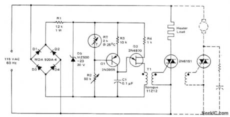
Use of phase control for triac provides gradual reduction in heater load current as desired temperature is approached, eliminating large overshoots. R2 is adjusted so al is of at desired temperature, turning Q2 off and preventing firing of triac. If temperature decreases, resistance of sensor RT increases and transistors initiate firing of triac.If RT continues to increase, C1 charges faster and triac is triggered earlier in each half-cycle, delivering more power to load. Dashed Iines indicate alternate connections for controlling motor with constant load such as blower motor. For cooling applications, interchange FIT and R2.- Circuit Applications for the Triac, Motorola, Phoenix, AZ, 1971, AN-466, p 9.
(View)
View full Circuit Diagram | Comments | Reading(1109)
LOW_POWER_PUSH_PULL_OUTPUT
Published:2009/7/21 7:44:00 Author:Jessie
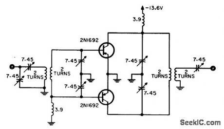
Efficiency is higher than with normal parallel output stage, yet overall efficiency is only 48% for 1.9-w output because emitter tuning is not effective and power gain is accordingly reduced.-W. A. Rheinfelder, Choosing the Best Transmitter Output State, EEE, 11:10, p 48-53. (View)
View full Circuit Diagram | Comments | Reading(750)
IMPLANTABLE_INGESTIBLE_ELECTRONIC_THERMOMETER
Published:2009/7/8 1:55:00 Author:May
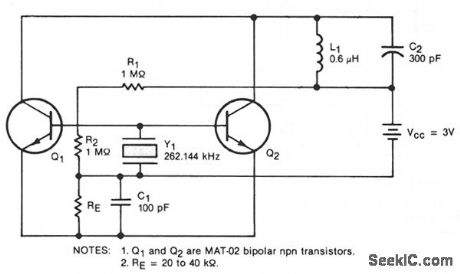
This oscillator circuit includes a quartz crystal that has a nominal resonant frequency of 262,144 Hz and is cut in the orientation that gives a large linear coefficient of frequency variation with the temperature.In this type of circuit, the oscillation frequency is controlled primarily by the crystal-as long as the gain-bandwidth product is at least four times the frequency. In this case, the chosen component values yield a gain-bandwidth product of 1 MHz. Inductor L1 can be made very small: 100 to 200 turns with a diameter of 0.18 in. (4.8 mm) and a length of 0.5 in. (12.7 mm). Although the figure shows two transistors in parallel, one could be used to reduce power consumption or three could be used to boost the output. The general oscillator circuit can be used to measure temperatures from -10 to + 140 °C. A unit made for use in the human body from about 30 to 40 °C operates at 262,144 ± 50 Hz with a frequency stability of 0.1 Hz and a temperature coefficient of 9 Hz/°C. (View)
View full Circuit Diagram | Comments | Reading(900)
THERMOCOUPLE_WITH_ZERO_VOLTAGE_SWITCH
Published:2009/7/8 1:55:00 Author:May
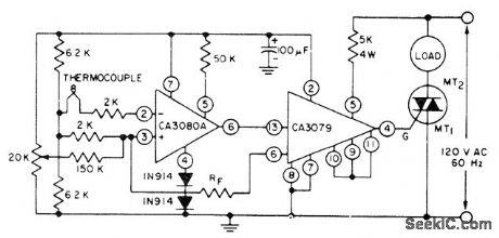
Differential input connection of RCA CA3080A operational transconductance amplifier is used with thernlocouple to drive CA3079 zero-voltage switch serving as trigger for triac handling AC load. Choose triac to match load being controlled. Supply voltage for opamps isnot criticaL.- Linear Integrated Circuits and MOS/FET's. RCA Solid State Division, Somerville, NJ, 1977, p 165-170.
(View)
View full Circuit Diagram | Comments | Reading(1431)
10_W_MARINE_BAND
Published:2009/7/8 1:53:00 Author:May
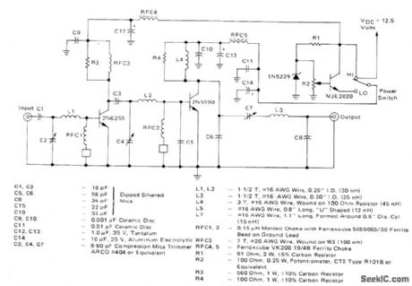
Power amplifier operating in class C from 12.5-VDC supply is designed for 152-162 MHz VHF marine band. Switch permits reducing power output to 1W or less. Tuning range of 144-175 MHz makes amplifier suitable for other applications such as amateur 2-meter and Iand-mobile radio. Power input is 181mW, power gain is 17.4dB, and effieiency is 44.5%.-J. Hatchett, 25-Watt and 10-Watt Marine Band Transmitters, Motorola, Phoenix, AZ, 1978, AN-595, p 4. (View)
View full Circuit Diagram | Comments | Reading(1439)
Projection_lamp_voltage_regulator_using_a_phototransistor_SOB_and_UJT
Published:2009/7/21 7:43:00 Author:Jessie
Projection lamp voltage regulator using a phototransistor, SOB and UJT (courtesy Motorola Semiconductor Products Inc.). (View)
View full Circuit Diagram | Comments | Reading(631)
SOUND_LEVEL_METER
Published:2009/7/8 1:53:00 Author:May
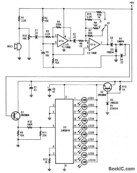
Sounds are picked up by MIC1 and fed to the input of the first op amp. The signal is then fed to the input of second op amp U1b, where it is boosted again by a factor of between 1 and 33, depending upon the setting of range switch S1.
With the range switch set in the A position, R6 is 1 KΩ and R7 is 33 KΩ, so that stage has a gain of 33.In the B position, the gain is 10Ω; in the C position, the gain is 22Ω; and in the D position the gain is 1 Ω.
As the signal voltage fed to the input of U2 at pin 5 varies, one of ten LEDs will light to correspond with the input-voltage level. At the input's lowest operating level, U2 produces an output at pin 1, causing LED1 to light. The highest input level presented to the input of U2, about 1.2 V, causes LED10 to turn on. (View)
View full Circuit Diagram | Comments | Reading(1)
LOW_DISSIPATION_SWITCH
Published:2009/7/8 1:53:00 Author:May
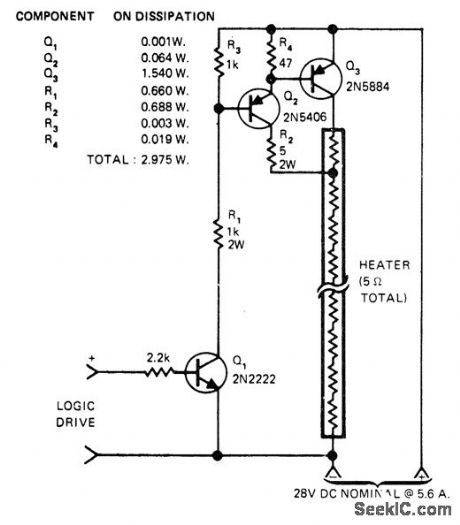
Logic-controlled power switch for 150-W instrument heater uses tap on heating element to force switch Q3, and driver Q2, into saturation and keep dissipation low. When input goes positive, Q1 turns on and drives Q2 and Q3 on. Collector current of Q2, and base drive of Q3 are determined by R2,. Voltage drop across R2 is proportional to supply voltage so drive for Q3 is at optimum level over wide voltage range,-M. Strange, Increase Electronic Power Switch Efficiency, EDN Magazine, Aug.20, 1975, p 78.
(View)
View full Circuit Diagram | Comments | Reading(790)
SIMPLE_CONTINUITY_TESTER
Published:2009/7/8 1:51:00 Author:May
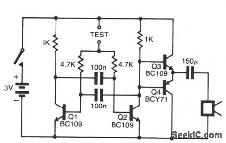
The pitch of the tone is dependent upon the resistance under test. The tester will respond to resistances of hundreds of kilohms, yet it is possible to distinguish differences of just tens of ohms in low-resistance circuits. Q1 and Q2 form a multivibrator, the frequency of which is influenced by the resistance between the test points. The output stage, Q3 and Q4, will drive a small loudspeaker or a telephone earpiece. The unit is powered by a 3-V battery, and draws very little current when not in use.
(View)
View full Circuit Diagram | Comments | Reading(0)
LOW_CURRENT_MEASUREMENT_SYSTEM
Published:2009/7/8 1:50:00 Author:May
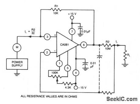
This circuit uses a CA018 BiMOS op amp. Low current, supplied at input potential as power supply to load resistor RL, is increased by R2/R1, when load current IL is monitored by power supply meter M. Thus, if IL is 100 rA, with values shown, IL presented to supply will be 100 ph. (View)
View full Circuit Diagram | Comments | Reading(830)
TEMPERATURE_MEASURING_ADD_ON_FOR_DMM_DIGITAL_VOLTMETER
Published:2009/7/8 1:50:00 Author:May
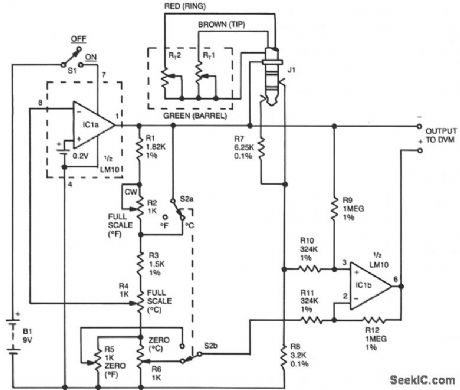
The DVM-to-temperature adapter is built around a single IC, National's LM10. That micropower IC contains a stable 0.2 V reference, a reference amplifier and a general-purpose op amp. The circuit is designed for a linear temperature range of 0 to 100 °C (32 to 212 °F). The 0.2-V reference and reference amplifier provide a stable, fixed-excitation voltage to the Wheatstone bridge. The voltage is determined by a feedback network consisting of R1 through R6. Switch S2a configures the feedback to increase the voltage from 0.6 V on the Celsius range to 1.08 V on the Fahrenheit range. These differences compensate for the fact that one degree Fahrenheit produces a smaller resistance change than does one degree Celsius.Resistors R1 through R16 also form the fixed leg of the Wheatstone bridge, nulling the bridge output at zero degrees. Since 0 °C is different from 0 °F, S2b is used to select the appropriate offset.The LM10's op amp, along with R9 through R12, form a differential amplifier that boosts the bridge output to 10 mV per degree. Since a single supply is used, and since the output must be able to swing both positive and negative, the output is referenced to the bridge supply voltage, rather than to the common supply. (View)
View full Circuit Diagram | Comments | Reading(1106)
TV_sound_channelwith_1_watt_output
Published:2009/7/21 7:41:00 Author:Jessie
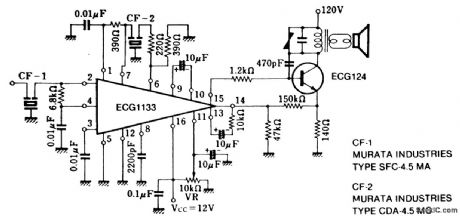
TV sound channelwith 1-watt output. The ECG1133 containsthree IF differential dmplifiers, a phase detector, a DC operated volume control and an AF amplifier. The IF specified is 4.5 MHz (courtesy GTE Sylvania Incorporated). (View)
View full Circuit Diagram | Comments | Reading(679)
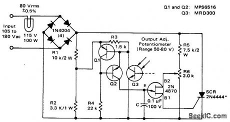
PHASE_FIRED_SCR_CONTROL
Published:2009/7/8 1:49:00 Author:May
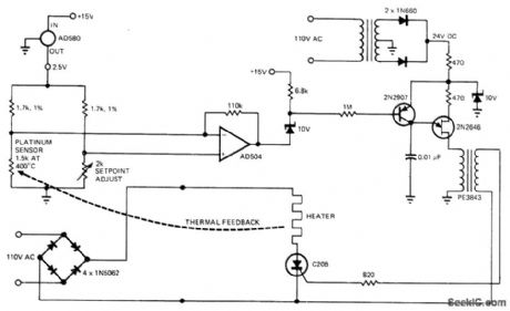
Can provide linear thermal control to 0.001℃ at high power with good efficiency. Band-gap voltage reference of AD580 IC temperature transducer furnishes power to bridge circuit, while platinum sensor provides sensing function, AD504 opamp amplifies bridge output for biasing 2N2907 transistor which in turn controis 60-Hz synchronized UJT oscillator that drives gate of SCR through isolation transformer. Biasing action makes SCR fire at different points on AC waveform as required for precise control of oven heater. Possibledrawback is RF noise generated because SCR chops in middle of wave-form,-J. Williams, Designer's Guide to: Temperature Control, EDNMagazine, June 20, 1977, p87-95. (View)
View full Circuit Diagram | Comments | Reading(864)
| Pages:967/2234 At 20961962963964965966967968969970971972973974975976977978979980Under 20 |
Circuit Categories
power supply circuit
Amplifier Circuit
Basic Circuit
LED and Light Circuit
Sensor Circuit
Signal Processing
Electrical Equipment Circuit
Control Circuit
Remote Control Circuit
A/D-D/A Converter Circuit
Audio Circuit
Measuring and Test Circuit
Communication Circuit
Computer-Related Circuit
555 Circuit
Automotive Circuit
Repairing Circuit