
Circuit Diagram
Index 974
CARRIER_SUPPRESSION
Published:2009/7/21 7:32:00 Author:Jessie
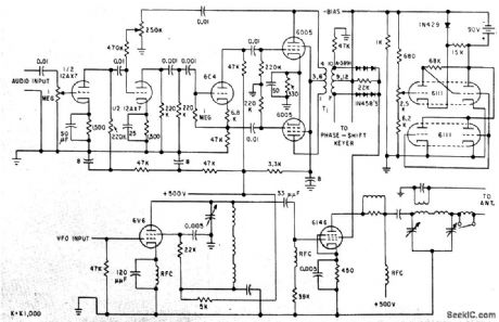
Suppressed-carrier modulation improves efficiency of medium-power transmitter and provides noise advantages of exalted-carrier detection in receiver.-J. Dysinger, W. Whyland, and R. Wood, New Suppressed-Carrier Modulation Technique, Electronics,33:6, p 47-49. (View)
View full Circuit Diagram | Comments | Reading(823)
DICE
Published:2009/7/7 22:16:00 Author:May
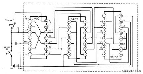
Simple low-cost arrangement of three ICs operating from 5-V battery (four nickel-cadmium or alkaline cells) provides bar display corresponding to spots on six sides of die. Uses SN7490N TTL decade counter with SN7405 hex inverter to drive Minitron 3015F seven-segment display. Article describes operation in detail and suggests variations for Arabic and binary displays.-G,J,Naaijer,Electronic Dice,Wireless World,Aug 1973,p401-403. (View)
View full Circuit Diagram | Comments | Reading(2063)
TV_video_signal_processor_circuit_1
Published:2009/7/21 7:32:00 Author:Jessie
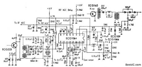
TV video signal processor circuit. The ECG1064 chip contains a first video amplifier, two sync pulse amplifiers, look-out protector, noise detector, two noise gates, AGC detector, IF AGC amplifier, BF AGC delay clamp, RF AGC amplifier, beam current limiter and syncpulse separator (courtesy GTE Sylvania Incorporated). (View)
View full Circuit Diagram | Comments | Reading(2024)
DUPLEX_LINE_AMPLIFIER
Published:2009/7/7 22:15:00 Author:May
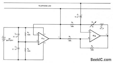
This circuit is a bidirectional amplifier that can amplify both signals of a duplex telephone conversation. It uses the principle of negative resistance. Obviously, such an amplifier could easily be unstable; however, you can adjust R1 for maximum amplification and the circuit will remain stable. The LM324 op amps can be replaced with op amps that would distort less, such as the LM1558, LF412, LF353, or LF442. (View)
View full Circuit Diagram | Comments | Reading(1169)
AC_controlled_triac_switch_R1_is_100_ohms
Published:2009/7/21 7:31:00 Author:Jessie
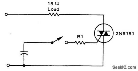
AC-controlled triac switch. R1 is 100 ohms (courtesy Motorola Semiconductor Products Inc.). (View)
View full Circuit Diagram | Comments | Reading(632)
TELEPHONE_SPEECH_ACTIVITY_DETECTOR
Published:2009/7/7 22:12:00 Author:May
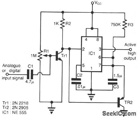
This circuit can be used in telephone lines for speech activity detection purposes. This detection is very useful in the case of half-duplex conversation between two stations-in the case of simultaneous transmission of voice and data over the same pair of cables by the method of interspersion data on voice trafftc, and also in echo suppressor devices. The circuit consists of a class-A amplifier to amplify the weak analog signals (25-400 mV). The IC1 which follows, is connected as a retriggerable monostable multivibrator with the TR2 discharging the timing capacitor C3, if the pulse train reaches the trigger input 2 of IC1 with period less than the time: THIGH =1.1 R3C3. The output 3 of IC1 is active on when an analog or digital signal is presented at the output, and it drops to a low level, THIGH, seconds after the input signal has ceased to exist. (View)
View full Circuit Diagram | Comments | Reading(2088)
RANDOM_FLASHING_NEONS
Published:2009/7/7 22:11:00 Author:May
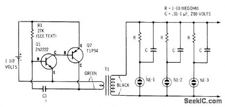
Neon glow lamps such as Radio Shack 272-1101 flash in unpredictable sequences at various rates that are determined by values of R and C used for each lamp, to give attention-getting display for classrooms and Science Fairs. Value of R1 can be as low as 2200 ohms for higher repetition rates, but battery drain increases. When circuit is energized, each neon receivesfull voltage and fires. Lamp capacitor begins charging, decreasing voltage across lamp until lamp goes out and cycle starts over. Use of different capacitor values makes lamps recycle at different rates. T1 is 6.3-VAC filament transformer used to step up oscillator voltage.-F. M. Mints, Transistor Projects, Vol, 2, Radio Shack, Fort Worth, TX,1974, p 43-52. (View)
View full Circuit Diagram | Comments | Reading(1071)
APPROXIMATING_SINES
Published:2009/7/7 22:10:00 Author:May
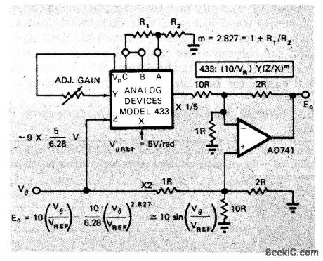
Analog Devices 433 multiplier/divider IC approximates sine of angle to less than 0.25% in lust two terms (one quad-rant). Arrangement requires only single opamp.Article gives analysis of theoretical errors and shows error curve.-D. H. Sheingold, Approximate Analog Functions with a Low-Cost Multiplier/Divider, EDN Magazine, Feb. 5, 1973, p 50-52. (View)
View full Circuit Diagram | Comments | Reading(679)
VOICE_OPERATED_CONTROL_WITH_DAMPING
Published:2009/7/21 7:31:00 Author:Jessie
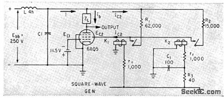
Relays provide timed sequential switching of pentode load to IC. filtered power supply when operator speaks into microphone, there by preventing over shoot.-E. L. Harris and O. J. M. Smith, Novel Circuit Damps Transients in Voice-operated Transmitters, Electronics, 35:39, p 66-67. (View)
View full Circuit Diagram | Comments | Reading(695)
REMOTE_TELEPHONE_RINGER
Published:2009/7/7 22:09:00 Author:May

The two neon bulbs will light when more than 100 V is across the ringing circuit. The bulbs provide line isolation between the unit and the telephone line. Finally, they act as a voltage divider for the bridge rectifier made up of D1 through D4. That voltage divider creates a positive voltage that is then applied through D5, is filtered by R2, R3, and C2, and causes Q1 and Q2 to conduct. When that happens, triac TR1 is fired through the optical coupler IC1; this turns on the triac, which applies 110 Vac to the load. (View)
View full Circuit Diagram | Comments | Reading(1587)
DIVlDER_SOUARE_ROOTER
Published:2009/7/7 22:08:00 Author:May
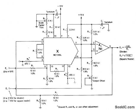
Modification of multiplier circuit gives divider in which negative output voltage is equal to 10 times ratio Ex/Ey. To use as square-rooter for Ex, connect pins 4 and 9 together and omit R1 and R2 at Ey input. Circuit uses multiplier block driving 741 current-to-voltage converter.-W. G. Jung, IC 0p-Amp Cookbook, Howard W. Sams, Indianapolis, IN, 1974, p 257-258. (View)
View full Circuit Diagram | Comments | Reading(957)
DICE_SIMULATOR
Published:2009/7/7 22:06:00 Author:May

Two 4018B synchronous counters are connected in modulo-6 walkingring sequences for driving LEDs to produce familiar die patterns. Pressing roll button starts gated astable that cycles first die hundreds of times and second die dozens of times, for randomizing of result. When roll button is released, final state of each die is held.-D. Lancaster, CMOS Cookbook, Howard W. Sams, Indianapolis, IN, 1977, p 324-325. (View)
View full Circuit Diagram | Comments | Reading(1564)
TELEPHONE_SOUND_LEVEL_METER_MONITOR
Published:2009/7/7 22:05:00 Author:May
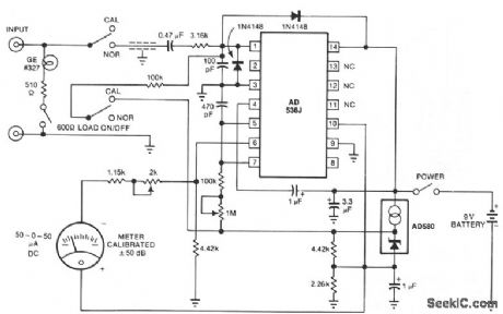
The telephone-line decibel meter and line-voltage sensor shown lets you accurately monitor and adjust telephone sound levels. The 600-Ω resistor properly terminates the line. Power drain from the 9-V battery is 2 mA, and the meter provides ±30 dB range. (View)
View full Circuit Diagram | Comments | Reading(1403)
MULTIPLIEB_DIVIDER
Published:2009/7/7 22:04:00 Author:May
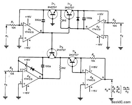
Combination opamp transistor circuit may be used for either multiplication or division, All signals must be of same polarity (positive). For multiplication, use in-puts e1 and e3 For division, use e1 and e2, with e3 being adjusted to give desired scaling factor. Log output at base of Tr2 is connected directly to antilog circuit at base of Tr3. Article gives de-sign equations. Circuit shown was developed to measure current gain of PNP transistor over range of operating currents.-G. B. Clayton, Experiments with Operational Amplifiers, Wire-less World, Feb. 1973, p 91-93. (View)
View full Circuit Diagram | Comments | Reading(1291)
DUAL_MOTOR_ROBOT
Published:2009/7/7 22:02:00 Author:May
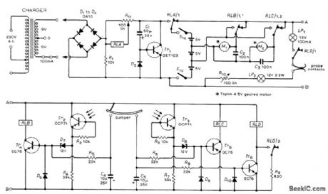
Battery-operated toy car roanis around room, reversing whenever it hits wall or obstdcle, and retums automatically to home base when batteries are in need of charge. Small geared motor, such as Meccano No.11057 or4.5-V Taplin, is used for each rear wheel so reversal of one motor provides steering. Single free-swiveling caster is at front of machine. With head-on collision, both contacts of bumper close to reverse both motors so machine backs away, turns, and proceeds in new direction. With glancing collision, motor on opposite sideis reversed so machine sheers away.White tape on floor, leading to charger having female lacks, is sensed by two phototransistors used to control motors so machine follows tape until probes at opposite end from bumper enter jacks. Circuit permits search mode for recharging only when relay D senses low battery voltage and energizes lamps that illuminate white tape. Article gives operation and construction details.-M. F. Huber, Free Roving Machine, Wireless World, Dec. 1972, p 593-594. (View)
View full Circuit Diagram | Comments | Reading(1768)
DIAL_PULSE_INDICATOR
Published:2009/7/7 22:01:00 Author:May
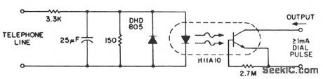
This indicator senses the switching on and off of the 48-Vdc line voltage and transmits the pulses to logic circuitry. An H11A10 threshold coupler, with capacitor ftltering, gives a simple circuit which can provide dial pulse indication, and yet reject high levels of induced 60-Hz noise. The DHD805 provides reverse bias protection for the LED during transient over-voltage situations. The capacitive ftltering removes less than 10 ms of the leading edge of a 40-V dial pulse, while providing rejection of up to 25-V rms at 60 Hz. (View)
View full Circuit Diagram | Comments | Reading(690)
Three_position_static_switch
Published:2009/7/21 7:31:00 Author:Jessie


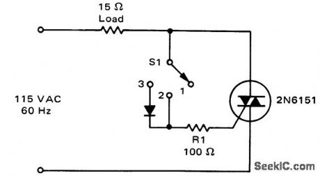
Three-position static switch. In position 1 the switch is off ; in position 2 the switch supplies full-wave power to the load; in position 3 the diode conducts only on half-cycles and the load is supplied with half-wave power (courtesy Motorola Semiconductor Products Inc.). (View)
View full Circuit Diagram | Comments | Reading(928)
LINEARIZING_X_INPUT
Published:2009/7/7 22:00:00 Author:May
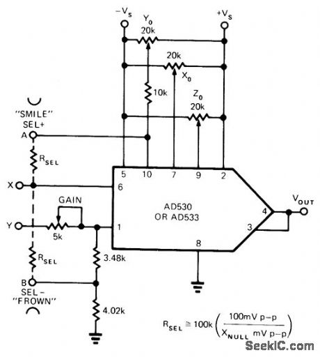
Adding resistors as shown to IC transconductance multiplier gives major improvement in X-input linearization. Article gives adjustment procedure. SMILE and FROWN terminal notes refer to X feedthrough pattern observed on CRO during setup, telling which position requires addition of RSEL resistor.-L. Counts, Reduce Multiplier Errors by up to an Order of Magnitude, EDN Magazine, March 20, 1974, p 65-68. (View)
View full Circuit Diagram | Comments | Reading(671)
TELEPHONE_HANDSET_ENCODER
Published:2009/7/7 21:58:00 Author:May
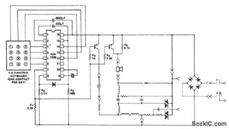
This encoder uses a single contact per key keyboard and provides all other switching functions electronically. The diode connected between terminals 8 and 15 prevents the output from goirfg more than 1 V negative with respect to the negative supply VSS. The circuit operates over the supply voltage range from 3.5 V to 15 V on the device side of the bridge rectifier. Transients as high as 100 V will not cause system failure, although the encoder will not operate correctly under these conditions. Correct operation will resume immediately after the transient is removed. The output voltage of the synthesized sine wave is almost directly proportional to the supply voltage (VDD - VSS) and will increase with the increase of supply voltage between terminals 8 and 16, after which the output voltage remains constant. (View)
View full Circuit Diagram | Comments | Reading(925)
PAGING_TRANSMITTER
Published:2009/7/21 7:30:00 Author:Jessie
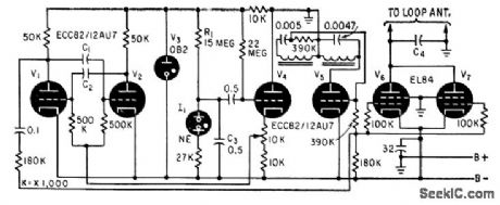
Feeds single-wire loop surrounding area to be covered. Multivibrator V1-V2 produces carrier frequencies in range from 15 to 30 kc, keyed on and off at various repetition rates in range from 1/50th to 1/200th second, for selective paging of up to 45 different receivers.-J. G. DeGraaf, Selective Paging System Uses Coded Transmission, Electronics, 33:9, p 68-70. (View)
View full Circuit Diagram | Comments | Reading(712)
| Pages:974/2234 At 20961962963964965966967968969970971972973974975976977978979980Under 20 |
Circuit Categories
power supply circuit
Amplifier Circuit
Basic Circuit
LED and Light Circuit
Sensor Circuit
Signal Processing
Electrical Equipment Circuit
Control Circuit
Remote Control Circuit
A/D-D/A Converter Circuit
Audio Circuit
Measuring and Test Circuit
Communication Circuit
Computer-Related Circuit
555 Circuit
Automotive Circuit
Repairing Circuit