
Circuit Diagram
Index 962
Half_wave_variable_AC_control_for_small_motors_and_lamps
Published:2009/7/21 5:38:00 Author:Jessie
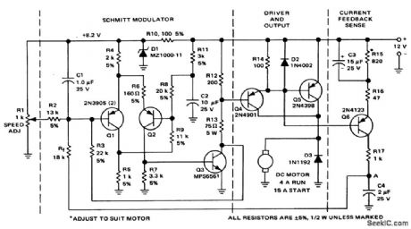
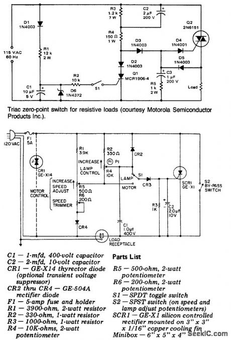
Half-wave variable AC control for small motors and lamps. In the lamp position the SCR is controlled by P1. In the motor position and with S2 open the circuit incorporates a feedback feature that maintains a constant motor speed as the load changes. Do not use this circuit for controlling fluorescent lamps, transformers, AC motors with capacitor start, induction motors, shaded pole motors and the like. The motor controlled must have a commutator as found in DC or AC-DC universal motors (courtesy General Electric Company). (View)
View full Circuit Diagram | Comments | Reading(975)
BUG_TRACER
Published:2009/7/8 4:06:00 Author:May
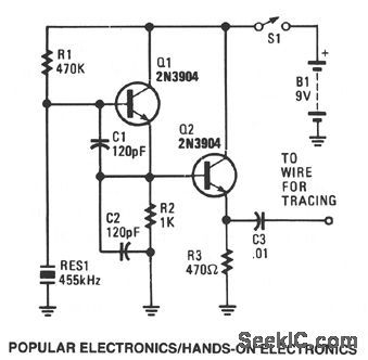
The bug tracer is made up of a simple rf-injector circuit consisting of Q1 and Q2, and a pocketsize, AM broadcast receiver. The two-transistor rf-injector circuit supplies a constant rf signal to one end of a cable. Then the AM receiver is used as a detector, allowing you to trace the wire to its source.
Transistor Q1, along with piezoelectric ceranuc resonator RES1, make up a simple rf oscillator that operates either at or near the AM-radio, 455-kHz, i-f frequency. That means that the second or third harmonic signal can easily be picked up by the receiver. Transistor Q2 is connected to an emitter-follower circuit to protect the oscillator from output loading; that helps to stabilize the output frequency and signal level. (View)
View full Circuit Diagram | Comments | Reading(3151)
PENTODE_7_KV_A_F_OSCILLATOR_TYPE_CRT_SUPPLY
Published:2009/7/21 5:37:00 Author:Jessie
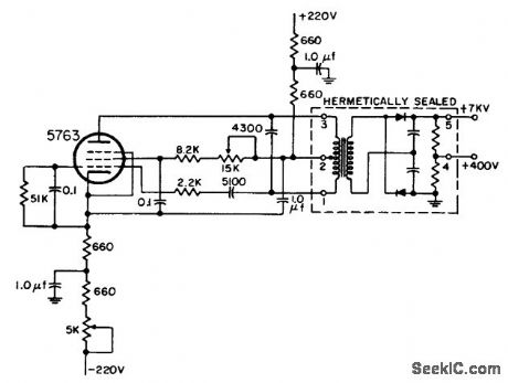
Example of 1958 circuit design, in which transformer, rectifiers, and filter are hermetically sealed in metal container. Oscillator frequency can be anywhere in range from 1 kc to 100 kc.-NBS, Handbook Preferred Circuits Navy Aeronautical Electronic Equipment, Vol. 1, Electron Tube Circuits, 1963, p N14-2. (View)
View full Circuit Diagram | Comments | Reading(638)
DUAL_TRIODE_7_KV_CRT_SUPPLY
Published:2009/7/21 5:36:00 Author:Jessie
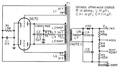
Serves as high-voltage source for screen grid and final anode of 5 to 12-inch cathode-ray tubes.CR1 and CR2 are each six 1N588 silicon diodes in series. Operating frequency is about 450 cps for twin-triode tuned-plate oscillator having high L-C ratio.-NBS, Hand-book Preferred Circuits Navy Aeronautical Electronic Equipment, Vol. I, Electron Tube Circuits, 1963, PC 6, p 6-2. (View)
View full Circuit Diagram | Comments | Reading(807)
PULSED_MARKER
Published:2009/7/21 5:34:00 Author:Jessie
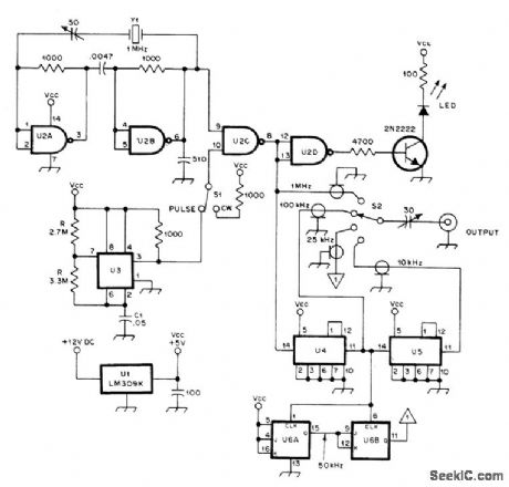
Crystal calibrator circuit provides pulsed output for easy spotting, eliminating need for turning marker on and off repeatedly to identify it in crowded band. With values shown, switching rate is about 2 Hz. When marker is found, placing S1 in CW position keeps it on for zero-beating calibrator output more accurately. Reducing value of C1 increases switching speed of U3, thus increasing pulse rate. LED indicates either pulsed or CW output. ICs are conventional types used in crystal calibrators.-R. G. Brunner, Crystal Calibrator Has Pulsed Output, QST, Nov. 1977, p 45. (View)
View full Circuit Diagram | Comments | Reading(854)
50_MHz_WITH_ATTEN_UATOR
Published:2009/7/21 5:33:00 Author:Jessie
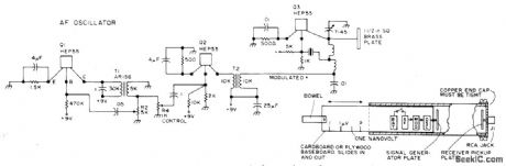
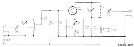
Positioning of miniaturized signal generator in 4 1/2 x 2 1/8 x 24 inch waveguide provides stable variable-strength signal that can be dropped gradually down to zero as generator is moved away from receiver pickup plate. Slide can be calibrated for measuring sensitivity of 6-meter receiver in tenths of a microvolt. Circuit consists of 50-MHz crystal oscillator, AF oscillator and simple class A modulator.-B, Hoisington, Low-Cost Infinite Attenuator for Amateur Use, 73 Magazine,Sept 1974,p107-108. (View)
View full Circuit Diagram | Comments | Reading(710)
28_MHz_LOW_NOISE
Published:2009/7/8 4:05:00 Author:May
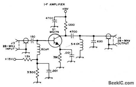
Developed for use with 2304-MHz balanced mixer. Provides required match between 50-ohm mixer output and input of 28-MHz IF amplifier in UHF receiver.Input and output connections are made with short lengths of RG-58/U coax. Noise figure is less than 1.5 dB.-L. May and B. Lowe, A Simple and Efficient Mixer for 2304 MHz, QST, April 1974, p 15-19 and 31. (View)
View full Circuit Diagram | Comments | Reading(798)
CENTRAL_IMAGE_CANCELLER
Published:2009/7/8 4:05:00 Author:May

The circuit allows you to eliminate the vocal potion of an audio signal, while leaving the instrumental portion. The circuit mixes two channels that must be 180° out of phase, so the signals that form the center-stereo image is canceled out. Those signals usually appear in phase. Resistor R3 biases the noninverting input of UI from a center tap formed by resistors RI and R4, and capacitor C3. Resistor R4, capacitor C3, and potentiometer R6 form a negative-feedback circuit that establishes the closed-loop voltage gain of UI at unity. The signal is inverted between the input and output. (View)
View full Circuit Diagram | Comments | Reading(662)
Triac_solid_state_relay_circuit_for_AC_power_control
Published:2009/7/21 5:33:00 Author:Jessie
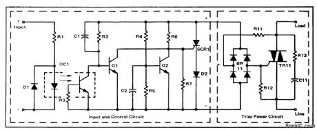
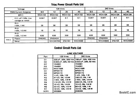
Triac solid-state relay circuit for AC power control. The input circuit will function over the range of 3 to 33 volts (courtesy Motorola Semiconductor Products Inc.). (View)
View full Circuit Diagram | Comments | Reading(1682)
TRACER_RECEIVER
Published:2009/7/8 4:04:00 Author:May
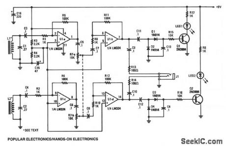
The tracer receiver is a stereo audio amplifier/detector circuit operating near 1 kHz. Inductors L1 and L2-hand-wound coils, consisting of 200 turns of #26 wire on 2-inch ferrite cores- are tuned to the operating frequency of the amplifier/detector. The received signal strength of each individual receiver is indicated by an LED. The audio output of the receiver is fed to a stereo headphone. That dual-receiver scheme helps in locating and tracking the hidden wire or cable by giving a directional output that indicates the cable's path.
The 1-kHz signal is picked up by L1 and coupled to the input of op amp U1a, which provides a gain of about 100 dB. The output of op amp U1a is fed through volume-control potentiometer R7 to the input of U1b, which magnifies the already amplified signal 100 times more. That puts the maximum gain of the receiver at about 10,000 dB. The output of U1b follows two paths: in the first path, the signal is couple through C9 and R13 to J1, and is used to drive one half of a stereo headphone.
In the other path, the signal is fed through a voltage doubling/detector circuit-consisting of Dl, D2, C11, and C13-that converts the amplified 1-kHz signal to the dc voltage that's used to drive Q1. When Q1 is turned on, LED1 lights, indicating a received signal. (View)
View full Circuit Diagram | Comments | Reading(3454)
TOUCH_SWITCH_2
Published:2009/7/8 4:02:00 Author:May
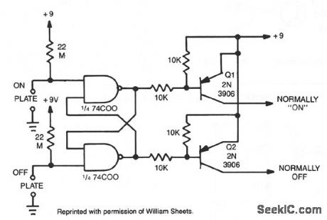
When the plate is touched, the gate input becomes low, changing the state of the latch.Q1 and Q2 give alternate N-on-N-off outputs. (View)
View full Circuit Diagram | Comments | Reading(1553)
IF_FILTER_FOR_CW
Published:2009/7/8 4:00:00 Author:May
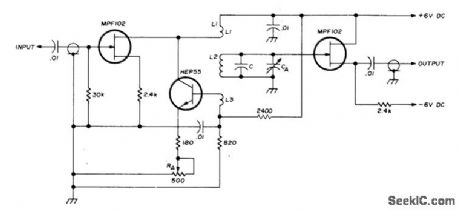
Circuit acts Iike variable filter having adjustable bandwidth, with enough gain to compensate for insertion Ioss in CW receiver. Used to isolate weak CW signals despite noise and interference, as required in lowpower amateur work. FET input is directly coupled to collector of HEP55 serving as Q.multiplier regenerative amplifier. Transformer L1-L3 provides feedback. Filter is connected in serieswith input end of IF strip,following 1.2-kHz mechanical filter. When two CW signals are received, one can be eliminated by adjusting CA to recenter passband of filter. Current drain of 6 mA can be supplied by two 6-V batteries. For 455-kHz IF, C is 470 pF, CA is 7-45 pF, and L1-L2-L3 are 12-115-24 turns No.32 enamel on Amidon T44-15 core.-S. M. Olberg, Vari-Q Filter, Ham Radio, Sept. 1973, p 62-65. (View)
View full Circuit Diagram | Comments | Reading(771)
5_MHz_STAN_DARD
Published:2009/7/21 5:32:00 Author:Jessie
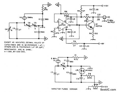
Guriot-Clapp crystal oscillator using broadband high-gain opamp U1 can be tuned by conventional variable capacitor C5 or alternatively by Motorola MV1650 varactor CR1. Buffer Q1 minimizes effect of loading on frequency.-R. Silberstein, An Experimental Frequency Standard Using ICs, QST, Sept. 1974, p 14-21 and 167. (View)
View full Circuit Diagram | Comments | Reading(616)
TOUCH_SWITCH_1
Published:2009/7/8 3:58:00 Author:May
View full Circuit Diagram | Comments | Reading(1436)
TOUCH_SWITCH
Published:2009/7/8 3:54:00 Author:May
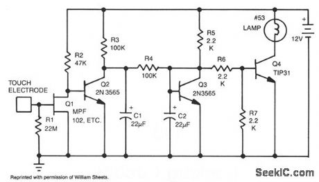
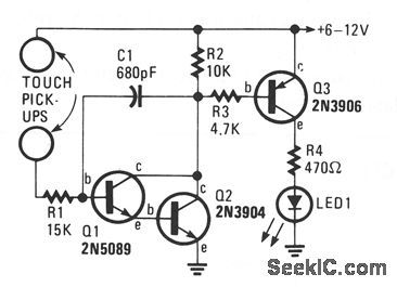
This touch-actuated switch stays on as long as you keep your finger on the touch plate. R1 sets the input impedance to a high 22 M Ω. Q1 picks up stray signals coupled through your body to the touch plate and amplifies them to tum on Q2, which tums on lamp drivers Q3 and Q4. Lamp I1 is any small 12-V lamp, such as a No. 53-12 V 120 mA. R4 and C1 add a small amount of hysteresis (delay) to keep the light from constantly flickering. A relay can be used for I1. (View)
View full Circuit Diagram | Comments | Reading(0)
455_kHz_WITH_PRODUCT_DETECTOR
Published:2009/7/8 3:50:00 Author:May
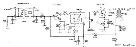
Bipolar transistor Q6 provides about 20-dB gain at 455 kHz, which is adequate for handling wide range of signal amplitudes without changing audio gain setting in receiver without AGC. Product detector produces output in audio range when its inputs are 455-kHz IF signal and BF0 signal near 455 kHz. Transistors can be 2N222, 2N3641, 2N4123, or equivalent. T1 is J. W. Miller 8814 455-kHz IF transformer/filter, T2 is miniature 455-kHz lF transformer, and T3 is miniature audiotransformer with 10K primary and 2K center-tap secondary (CT not used).-D. DeMaw and L. McCoy, Leaming to Work with Semiconductors, QST, Aug. 1974, p 26-30. (View)
View full Circuit Diagram | Comments | Reading(4027)
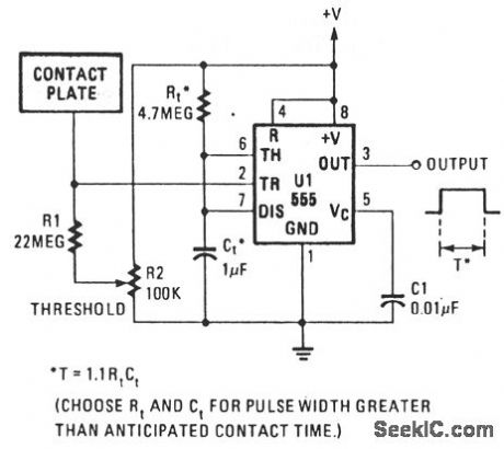
LINE_HUM_TOUCH_SWITCH
Published:2009/7/8 3:47:00 Author:May
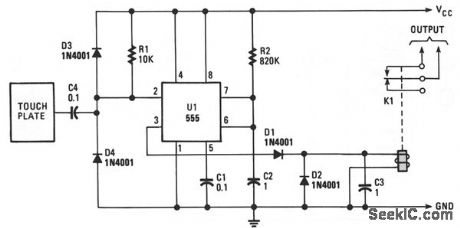
The monostable period is set for about 1 second, as is the usual case. The induced line hum comes through C2, providing a continuous string of trigger pulses. The output becomes low for about 10 ms per second as the monostable times out and then retriggers. Diode Dl and capacitor C3 buffer the relay so it doesn't chatter on those 10-ms pulses. Resistor R2 sets the sensitivity.The relay energizes when the plate is touched and de-energizes, up to one second after the finger is removed. The delay is a function of when the monostable last retriggered. (View)
View full Circuit Diagram | Comments | Reading(1028)
TOUCH_ON_OFF_ELECTRONIC_SWITCH
Published:2009/7/8 3:45:00 Author:May

Transistors Q1 and Q2 control latch Q3 and Q4 to switch on the lamp. A high resistance from touching the electrode biases Q1 or Q2 on, setting or resetting the latch. (View)
View full Circuit Diagram | Comments | Reading(892)
120_144_MHz
Published:2009/7/8 3:44:00 Author:May
General-purpose amplifier can be used around 120 MHz as microwave IF strip and up to 144 MHz for RF. Transistor type is not critical.-B. Hoisington, DC lsolation, 73 Magazine,Peterborough NH 03458,July 1974,p 55-62. (View)
View full Circuit Diagram | Comments | Reading(659)
TWO_TERMINAL_TOUCH_SWITCH
Published:2009/7/8 3:43:00 Author:May
This circuit requires the bridging of two circuits to activate the electronic switch. That circuit does not require a 60-Hz field to operate and can be battery or ac powefed. The two-pickup terminals can be made from most any clean metal; they should be about the size of a penny. The input circuitry of the two-terminal touch switch is a high-gain Darlington amplifier that multiplies the small bridging current to a value of sufficient magnitude to turn on Q3, supplying power to LED1. If a quick on and off switching time is desired, the value of C1 should be very small; if a long on-time period is required, the value of C1 can be increased. (View)
View full Circuit Diagram | Comments | Reading(796)
| Pages:962/2234 At 20961962963964965966967968969970971972973974975976977978979980Under 20 |
Circuit Categories
power supply circuit
Amplifier Circuit
Basic Circuit
LED and Light Circuit
Sensor Circuit
Signal Processing
Electrical Equipment Circuit
Control Circuit
Remote Control Circuit
A/D-D/A Converter Circuit
Audio Circuit
Measuring and Test Circuit
Communication Circuit
Computer-Related Circuit
555 Circuit
Automotive Circuit
Repairing Circuit