
Circuit Diagram
Index 971
TEMPERATURE_CONTROLLER
Published:2009/7/7 23:07:00 Author:May
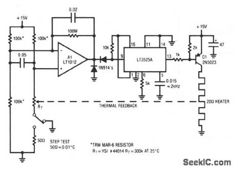
When power is applied, the thermistor, a negative tc device, is at a high value. A1 saturates positive.This forces the LT3525A switching regulator's output low, biasing Q1. As the heater warms, the thermistor's value decreases. When its inputs finally balance, A1 comes out of saturation and the LT3525A pulsewidth modulates the heater via Q1, completing a feedback path. A1 provides gain and the LT3525A is highly efficient. The 2-kHz, pulse-width modulated heater power is much faster than the thermal loop's response, and the oven sees an even, continuous heat flow. (View)
View full Circuit Diagram | Comments | Reading(0)
VERY_SHORT_PULSE_WIDTH_MEASURER
Published:2009/7/7 23:06:00 Author:May
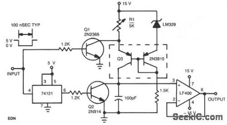
This circuit operates by charging a small capacitor from a constant-current source when the pulse to be measured is present. Dual pnp transistor Q3 is the current source; its output current equals the LM329 reference voltage divided by the resistance of potentiometer R1. When the input is high with no pulse present, Q1 keeps the current source turned off. When the pulse begins and the input decreases, Q1 turns off and the monostable multivibrator generates a short pulse. The pulse from the multivibrator turns on Q2, removing any residual charge from the 100-pF capacitor. Q2 then turns off, and the capacitor begins to charge linearly from the current source. When the input pulse ends, the current source turns off, and the voltage on the capacitor is proportional to the pulse width.
(View)
View full Circuit Diagram | Comments | Reading(719)
FOUR_QUADRANT_8_BIT
Published:2009/7/7 23:06:00 Author:May
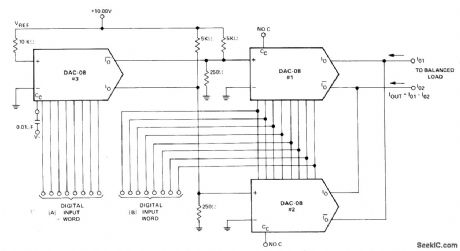
Requires only three Precision Monolithics DAC-08D/A converters to provide high-speed multiplication of two 8-bit digital words and give analog output.-J Schoeff and D. Soderquist, Differential and Multiplying Digital to Analog Converter Applications, Precision Monolithics, Santa Clara.CA,1976,AN-19,p7. (View)
View full Circuit Diagram | Comments | Reading(726)
TACHOMETER_AND_DIRECTION_OF_ROTATION_CIRCUIT
Published:2009/7/7 23:05:00 Author:May
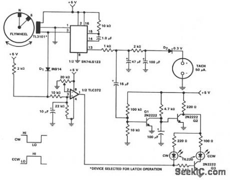
In machine and equipment design, some applications require measurement of both the shaft speed and the direction of rotation. Fig. 56-4 shows the circuit of a tachometer, which also indicates the direction of rotation. The flywheel has two magnets embedded in the outer rim about 45° apart. One magnet has the north pole toward the outside and the other magnet has the south pole toward the outside rim of the flywheel. Because of the magnet spacing, a short on pulse is produced by the TL3101 in one direction and a long on pulse in the other direction. A 0-50 μA meter is used to monitor the flywheel speed while the LEDs indicate the direction of rotation. The direction-of-rotation circuit can be divided into three parts:
· TLC372 device for input conditioning and reference adjustment.· Two 2N2222 transistors which apply the VCC to the two LEDs when needed.· The two TTL 220 LEDs which indicate clockwise (CW) or counterclockwise (CCW) direction of rotation. (View)
View full Circuit Diagram | Comments | Reading(1180)
SERVO_SENSED_HEATER_PROTECTOR
Published:2009/7/7 23:03:00 Author:May
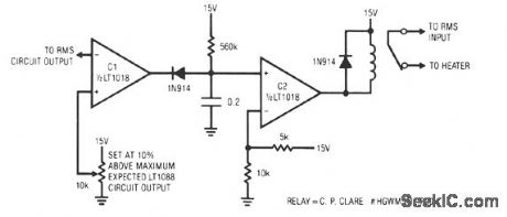
This circuit responds quickly enough to prevent damage from most overloads. C1's input is connected to the output of the LT10ss servo circuit. If the LT1088 circuit's output exceeds the threshold at C1's other input, C1 trips, discharging the 2-μF capacitor. This causes C2's output to become low, energize the relay, and break the heater circuit. The 560-KΩ resistor provides a long recharge for the capacitor, preventing chattering action. This arrangement's speed of response is limited by the rms circuit's slew rate, about 0.2 V/ms. For reasonable overloads, the LT1088's temperature increases about 1°C/ms. A 10-V LT1088 output step takes 50 ms, causing a temperature rise of about 50°C. (View)
View full Circuit Diagram | Comments | Reading(780)
LC_CHECKER
Published:2009/7/7 23:03:00 Author:May
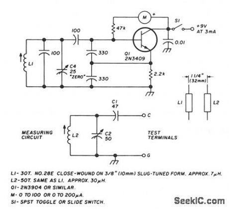
The circuit is based on the grid-dip or absorption effect, which occurs when a parallel resonant circuit is coupled to an oscillator of the same frequency. Q1 operates in a conventional Colpitts oscillator circuit at a ftxed frequency of approximately 4 MHz. A meter connected in series with the transistor's base-bias resistor serves as the dip or absorption indicator.The variable measuring circuit consists of C1, C2, and L2 and is connected to panel terminals as shown. L2 is loosely coupled to L1 in the oscillator circuit. This measuring circuit is tuned to the oscillator frequency with variable capacitor C2 set at full capacitance. When power is applied to the oscillator, the meter shows a dip caused by power absorption from the measuring circuit.Connecting an unknown capacitor across the test terminals lowers the resonant frequency of the measuring circuit. To restore resonance, tune capacitor C2 lower in capacitance. The meter will dip again when you reach this point. Determine the capacitance across the text terminals by calibrating the dial settings of C2.Capacitor C4, a small variable trimmer in the oscillator circuit, compensates for drift or other variations and is normally set at half capacitance. The capacitor is a panel control, labeled zero, and it is used to set the oscillator exactly at the dip point when C2 is set at maximum capacitance. This corresponds to zero on the calibration scale.
(View)
View full Circuit Diagram | Comments | Reading(3738)
AC_COUPLED_MU_LTIPLICATION
Published:2009/7/7 23:02:00 Author:May
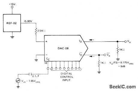
Combination of Precision Monolithics REF-02 voltage reference and DAC-08 DIA converter uses compensation capacitor terminal Cc as input. With full-scale input code, output Vo is flat to above 200 kHz and 3 dB down at 1 MHz, for multiplying applications far beyond audio range. Circuit has high input impedance, as often required to avoid loading high source impedance. Dynamic range is greater than 40 dB.-J. Schoeff and D. Soderquist, Differential and Multiplying Digital to Analog Converter Applications, Precision Monolithics, Santa Clara, CA, 1976, AN-19, p 4. (View)
View full Circuit Diagram | Comments | Reading(1421)
LED_PEAKMETER
Published:2009/7/7 22:59:00 Author:May
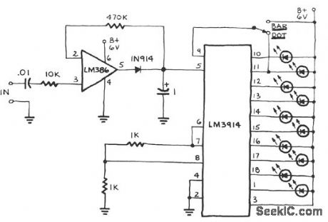
The circuit includes a peak detector that immediately drives the readout to any new higher signal level and slowly lowers it after the signal drops to zero. The readout is a moving dot or expanding bar display.The circuit can be expanded for a longer bar readout. Tapping five or more LED peakmeters into a frequency equalizer or series of audio filters should give a unique result. The bottom LED remains on with no signal at the input, thus providing a pilot light for the unit. (View)
View full Circuit Diagram | Comments | Reading(1564)
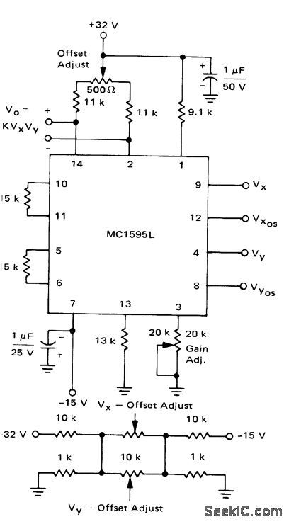
_OUTPUT_LEVEL_SHIFTER
Published:2009/7/7 22:58:00 Author:May
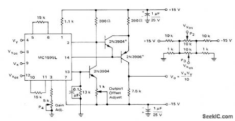
Transistors connected to Motorola MC1595L linear four-quadrant multiplier perform level shifting for applications requiring output having ground reference. Temperature sensitivity of circuit is minimized by using complementary transistors in same package, such as MD6100, in place of upper two transistors. If high output impedance and low current drive are drawbacks, opamp can be connected as source-follower output stage.-E. Renschler, Analysis and Basic 0peration of the MC1595, Motorola, Phoenix, AZ, 1975, AN-489, p 10. (View)
View full Circuit Diagram | Comments | Reading(1659)
ZERO_POINT_SWITCHING_TEMPERATURE_CONTROL
Published:2009/7/7 22:58:00 Author:May
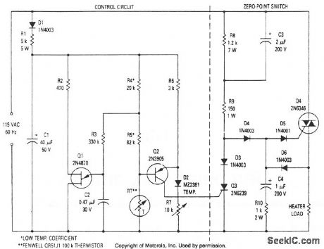
This modulated triac zero-point switching circuit controls heater loads operating from 115 Vac. Circuit operation is best described by splitting the circuit into two parts. The circuit at right is the zero-point switch; to the left is the proportional control for the zero-point switch. (View)
View full Circuit Diagram | Comments | Reading(930)
WIDE_RANGE_RF_POWER_METER
Published:2009/7/7 22:58:00 Author:May
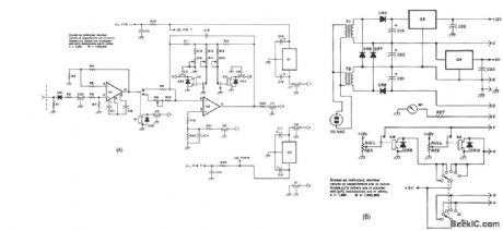


The Hewlett-Packard HSCH-3486 zero-bias Schottky diode is used as the detector.To avoid using a modulation method of detection,a chopper-stabilized op amp is used.The chopper op amp basically converts the mput dc voltage to ac,amplifiesit,and converts it back to dc.Amplifying the dc output from the detector 150 times with a chopper opamp puts the signal at a level that simpler op amps,such as the LM11,can handle, Offset voltages hthe amplifier are nulled with two pots one for the lower three ranges. (View)
View full Circuit Diagram | Comments | Reading(1460)
ON_OFF_HEATER_CONTROL
Published:2009/7/7 22:57:00 Author:May
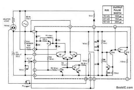
Uses Texas In-struments SN72440 zero-voltage switch to trigger triac that turns AC heater on and off in acl cordance with demands of 8K resistance-type temperature sensor. One output pulse per zero crossing of AC Iine voltage is either inhibited or permitted by action of differential amplifier and resistance bridge circuit in IC. Width of output pulse at pin10 is controlled by trigger pot R20 as given in table and should be varied to suit triggering characteristics of triac used.- The Linear and Interface Circuits Data Book for Deislgn Engineers, Texas Instruments,Dallas,TX,1973,p7-37
(View)
View full Circuit Diagram | Comments | Reading(1246)
TELEPHONE_TAP
Published:2009/7/7 22:55:00 Author:May
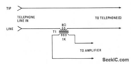
Amplify or record a telephone call with the simple circuit shown. The 8-Ω secondary winding of a min-iature transistor output transformer is connected in series with either of the telephone lines. The 1000-Ω primary winding can feed either a cassette recorder or an audio amplifier. (View)
View full Circuit Diagram | Comments | Reading(935)
75_250℃_OVEN_CONTROL
Published:2009/7/7 22:55:00 Author:May
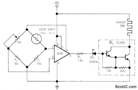
Provides propor-tional temperature control of small oven to within 1℃ over temperature range. Uses 823B voltage regulator operating from same 28-V source as oven. Temperature-setting pot should be 10-turn wirewound. Powertransistor Q1operates either saturated or almost cut off, so no heatsink is required.-R. L. Wilbur, Pro-portional Oven-Temperature Controller, EDNlEEEMagazine, Sept. 15, 1971, p 45. (View)
View full Circuit Diagram | Comments | Reading(738)
LED_DIE
Published:2009/7/7 22:54:00 Author:May
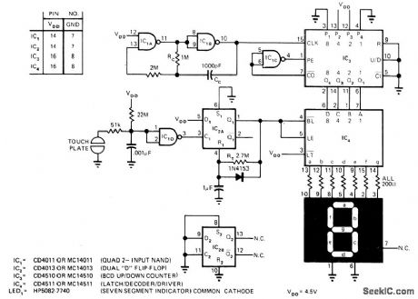
When positive bias on input of IC1D number displayed. Number can be between 1 NAND gate is puiied to ground by skin resistance of finger, D flip-flop IC2A connected as mono is triggered. Pin 1 goes high for about 2 s, making IC4. latch outputs of counter IC3 andunblank LED display. Randomtime that fingeris on touch plate determines randomness of number displayed. Number can be between 1 and9, between 1 and 6 for die,between 1 and2 to representheads or tailsChange BCDof jam inputs of IC3 to highest random number desired .Values shown are for 4.5-V supply and dispiay current of 10 mA PER SEGMENT. LEDisblanked until plateis touched Standby current drain of 10 μA on three AA alkaline cellsis so low that ON/OFF switch is unnecessary.-C,Cullings,Electronic Die Uses Touchplate and 7Segment LED Disρlay,EDN Magazine,May 20,1975、p70 and 72. (View)
View full Circuit Diagram | Comments | Reading(1497)
TELEPHONE_AMPLIFIER
Published:2009/7/7 22:53:00 Author:May
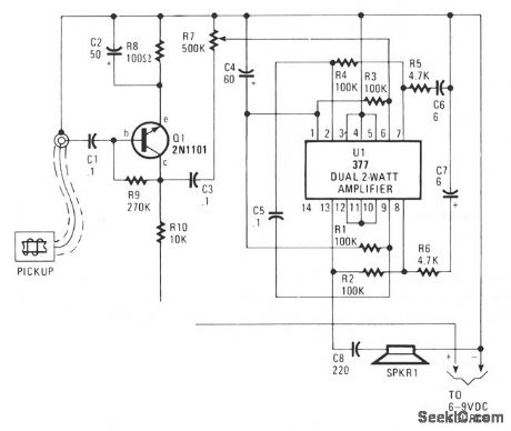
Audio from the telephone is inductively coupled to the base of Q1, which is used as a preamp. The preamp provides a gain of about 75 dB, to boost the input signal from about 4 mV to about 300 mV pk-pk. If you use a higher gain transistor, increase the value of R9 to produce a Q point, measured from minus to the collector of Q1, of one-half the supply voltage. The Q1 output signal is coupled through C3 to R7, which serves as a volume or drive-level control, to U1, a dual, 2 w amplifier connected in cascade. Pins 1 through 7 serve as a driver for the final amplifier, pins 8 through 13. Compensation and balance is accomplished by components R1 through R6 and C4, C6, and C7. Pins 3 through 5, and 10 through 12 should be tied to the negative supply rail. (View)
View full Circuit Diagram | Comments | Reading(0)
F_M_WIRELESS_MICROPHONE
Published:2009/7/21 7:28:00 Author:Jessie
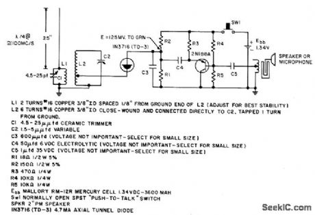
Transmitter has range of 200 yards when used with sensitive commercial receiver covering 96-110 Mc. Transistor stage frequency-modulates tunnel-diode oscillator, - Transistor Manual, Seventh Edition, General Electric Co., 1964, p 357. (View)
View full Circuit Diagram | Comments | Reading(1296)
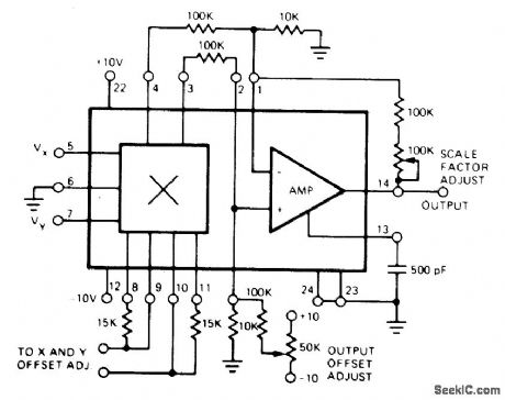
FOUR_QUADRANT
Published:2009/7/7 22:53:00 Author:May
Motorola MC1595L linear four-quadrant multiplier takes two different input voltages, each between -10V and +10V, and gives output equal to one-tenth of their product. Circuit can be operated in either AC or DC mode. Design and setup procedures are given.-E. Renschler, Analysis and Basic Operation of the MC1595, Motorola, Phoenix, AZ, 1975, AN-489 p 8. (View)
View full Circuit Diagram | Comments | Reading(866)
OVEN_CONTROL
Published:2009/7/7 22:52:00 Author:May
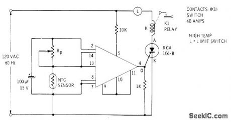
Simple circuit using RCA CA3059 zero-crossing switch regulates ON and OFF intervals of low-current SCR that controls solenoid in electric or gas oven. Sensor resistor has negative temperature coefficient. RP, is set for desired control temperature.-E. M. Noll, Linear IC Principles, Experiments, and Proj-ects, Howard W. Sams, Indianapolis, IN, 1974, p323.
(View)
View full Circuit Diagram | Comments | Reading(2215)
ANALOG_MULTIPLIER
Published:2009/7/7 22:51:00 Author:May
Multiplier and amplifier sections of Exar XR-S200 PLL IC are combined to perform analog multiplication without need for DC level shifting between input and output. Single-ended output is at ground level. - Phase-Locked Loop Data Book, Exar Integrated Systems, Sunnyvale, CA, 1978, p 9-16. (View)
View full Circuit Diagram | Comments | Reading(0)
| Pages:971/2234 At 20961962963964965966967968969970971972973974975976977978979980Under 20 |
Circuit Categories
power supply circuit
Amplifier Circuit
Basic Circuit
LED and Light Circuit
Sensor Circuit
Signal Processing
Electrical Equipment Circuit
Control Circuit
Remote Control Circuit
A/D-D/A Converter Circuit
Audio Circuit
Measuring and Test Circuit
Communication Circuit
Computer-Related Circuit
555 Circuit
Automotive Circuit
Repairing Circuit