
Circuit Diagram
Index 970
TV_horizontal_AFC_and_oscillator_with_sync_separator_for_negative_sync_using_an_ECG1086_16_pin_DIP
Published:2009/7/21 6:46:00 Author:Jessie
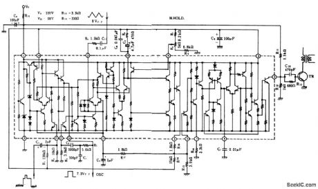
TV horizontal AFC and oscillator with sync separator for negative sync, using an ECG1086 16-pin DIP. The singletransistor stage is the horizontal driver and can be an ECG199 bipolar transistor (courtesy GTE Sylvania Incorporated). (View)
View full Circuit Diagram | Comments | Reading(1010)
MOTOR_HOUR_METER
Published:2009/7/7 23:18:00 Author:May
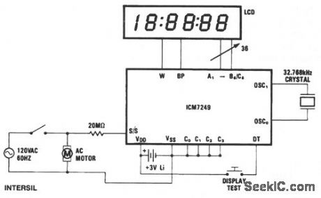
In this application, the ICM7249 is conftgured as an hours-in-use meter and shows how many whole hours of line voltage have been applied. The 20-MΩ resistor and high-pass ftltering allow ac line activation of the S/S input. This configuration, which is powered by a 3-V lithium cell, will operate continuously for 21/2 years. Without the display, which only needs to be connected when a reading is required, the span of operation is extended to 10 years.
(View)
View full Circuit Diagram | Comments | Reading(0)
TV_horizontal_AFC_and_oscillator_with_sync_separator_for_positive_sync_using_an_ECG1086_16_pin_DIP
Published:2009/7/21 6:43:00 Author:Jessie
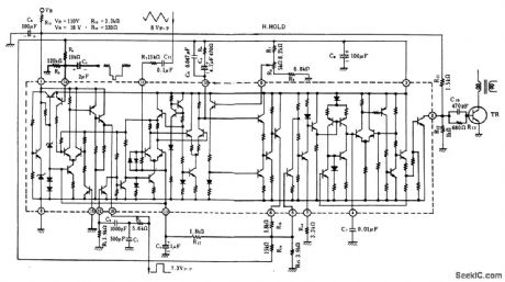
TV horizontal AFC and oscillator with sync separator for positive sync, using an ECG1086 16-pin DIP. The single transistor shown is an ECG199, a horizontal driver stage (courtesy GTE Sylvania Incorporated). (View)
View full Circuit Diagram | Comments | Reading(1306)
SQUARING_FOR_RMS
Published:2009/7/7 23:17:00 Author:May
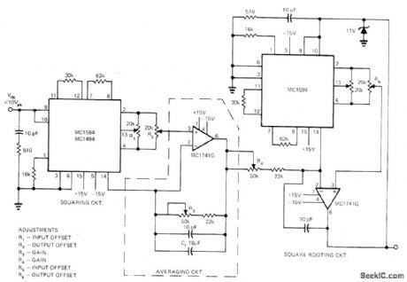
Combination of two MC1594 multipiiers and two opamps gives RMS detector for squaring instantaneous input values, averaging over time interval, then taking square root to give RMS value of input wave-form. First multiplier, used to square input waveform, delivers output current to first opamp for conversion to voltage and for aver-aging by means of capacitor in feedback path. Second opamp is used with second multiplier as feedback element for taking square root. Technique eliminates thermal response time drawback of most other RMS measuring circuits. Input voltage range for circuit is 2 to 10 V P-P; for other ranges, input scaling can be used. Since direct coupling is used, output voltage in. dudes DC components of input. Maximum input frequency is about 600 kHz, and accuracy is about 1%,-K. Huehne and D. Aldridge, True RMS Measurements Using IC Multipliers, EDN Magazine, March 20, 1973, p 85-86. (View)
View full Circuit Diagram | Comments | Reading(955)
SILICON_TRANSISTORS_MINIMIZE_POWER_DRAIN
Published:2009/7/21 6:32:00 Author:Jessie
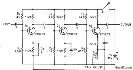
Used in conjunction with high-value circuit resistances to permit operation of preamplifier with battery drain of less than 1 nw. Gain is 100 for bandwidth of 18 kc. Intended primarily for use at room temperature.-C. D. Todd, Preamplifier Designed for Minimum Power Consumption, Electronics, 33:18, p 106-107. (View)
View full Circuit Diagram | Comments | Reading(707)
PRECISION_FREQUENCY_COUNTER_TACHOMETER
Published:2009/7/7 23:16:00 Author:May
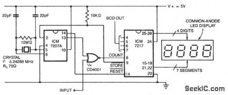
In this configuration, the display reads hertz directly. With pin 11 of the ICM7027A connected to VDD, the gating time will be 0.1 second; this will display tens of hertz as the least significant digit. For shorter gating times, an ICM7207 can be used with a 6.5536-MHz crystal, giving a 0.01 second gating with pin 11 connected to VDD, and a 0.1 second gating with pin 11 open. (View)
View full Circuit Diagram | Comments | Reading(1882)
DIRECT_COUPLED_PREAMPLIFIER
Published:2009/7/21 6:31:00 Author:Jessie
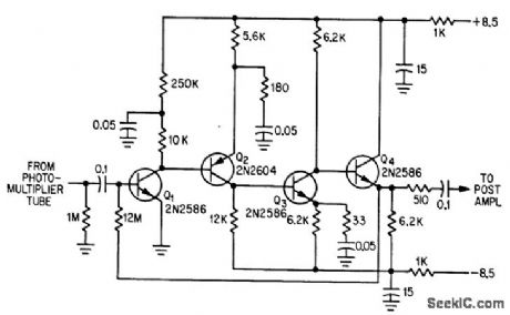
Output of multiplier phototube in orbiting astronomical observatory receives closed-loop amplification of 12 in current-sensing preamplifier over input dynamic current range of 3 to 500 ma. -R. Cuikay and T. Callahan, Orbiting Observatory to Measure Stars' Dim Light, Electronics, 37:9, p 28-31. (View)
View full Circuit Diagram | Comments | Reading(836)
AUTOPILOT_PREAMP
Published:2009/7/21 6:29:00 Author:Jessie
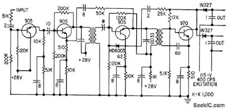
Reliable pitch-axis channel uses four npn silicon transistors.-C. W. McWilliams, Designing Safety Into Automatic Pilot Systems, Electronics, 31:45, p 69-71. (View)
View full Circuit Diagram | Comments | Reading(624)
6217_PHOTOMULTIPLIER_PREAMP
Published:2009/7/21 6:27:00 Author:Jessie
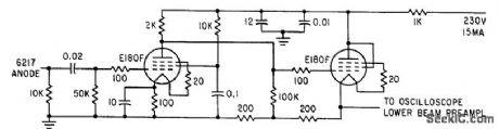
Used between photomultiplier and dual-beam oscilloscope to amplify signal pulse corresponding to transmitted laser signal in optical ranging system. Distance between transmitted and received pulses on cro corresponds to range. -M. L. Stitch, E. J. Woodbury and J. H. Morse, Optical Ranging System Uses Laser Transmitter, Electronics, 34:16, p 51-53. (View)
View full Circuit Diagram | Comments | Reading(656)
STUD_FINDER
Published:2009/7/7 23:15:00 Author:May

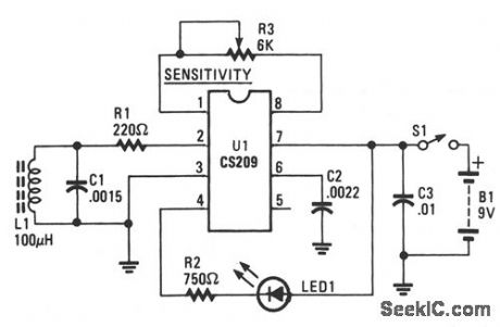
The CS209 is designed to detect the presence or proximity of magnetic metals. It has an internal oscillator that, along with its extemal lc resonant circuit, provides oscillations whose amplitude is dependent upon the Q of the lc network. Close proximity to magnetic material reduces the Q of the tuned circuit, thus the oscillations tend to decrease in amplitude. The decrease in amplitude is detected and used in tum on LED1, indicating the presence of a magnetic material (i.e., nail or screw). (View)
View full Circuit Diagram | Comments | Reading(3317)
PAPER_SHEET_DISCRIMINATOR_FOR_PRINTING_AND_COPYING_MACHINES__
Published:2009/7/7 23:14:00 Author:May
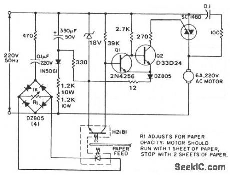
The circuit outputs power to the drive motor when one or no sheets are being fed, but interrupts motor power when two or more superimposed sheets pass through the optodetector slot. The optodetector can be either an H2aB darlington interruptor module or an H23B matched emitter-detector pair. The output from the optodarlington is coupled to a Schmitt trigger, comprising transistors Q1 and Q2 for noise immunity and minor paper opacity variation immunity. When the Schmitt is on, gate current is applied to the SC148D output device. The dc power supply for the detector and Schmitt is a simple rc diode halfwave configuration chosen for its low cost (fewer diodes and no transformers) and minimum bulk. While such a supply is directly coupled to the power triac, this is precluded by current drain considerations (50 mA dc for the gate drive alone). Note that direct coupling of the Schmitt to the output triacs is preferred, since RFI is virtually eliminated with the quasi-dc gate drive. (View)
View full Circuit Diagram | Comments | Reading(699)
TV_video_IF_amplifier_video_detector_and_signal_processor_circuits_Used_in_color_and_BW_TVs
Published:2009/7/21 6:26:00 Author:Jessie
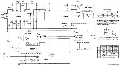
TV video IF amplifier, video detector, and signal processor circuits. Used in color and B&W TVs (courtesy GTE Sylvania Incorporated). (View)
View full Circuit Diagram | Comments | Reading(1726)
PROPORTIONAL_TEMPERATURE_CONTROLLER
Published:2009/7/7 23:13:00 Author:May
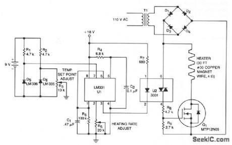
This temperature controller operates as a fiulse snatching device, which allows it to run at its own speed and turn on at the zero crossing of the line frequency. Zero crossing turn-on reduces the generation of line noise transients. TMOS Power FET, Q1, is used to turn on a heater.
Temperature sensor D6 provides a dc voltage proportional to temperature that is applied to voltage-to-frequency converter U1. Output from U1 is a pulse train proportional to temperature offset that is applied to the input of triac optoisolator U2. The anode supply for the triac is a 28 V pk-pk, full-wave rectifted sine wave. The optoisolator ORs the pulse train from U1 with the zero crossing of U2's anode supply, supplying a gate tum on signal for Q1. Therefore, TMOS power FET Q1 can only turn the heater on at the zero crossing of the applied sine wave. The maximum temperature, limited by the sensor and the insulation of the wire, is 130°C for the components shown. (View)
View full Circuit Diagram | Comments | Reading(3134)
7326_PHOTOMULTIPLIER_PREAMP
Published:2009/7/21 6:26:00 Author:Jessie
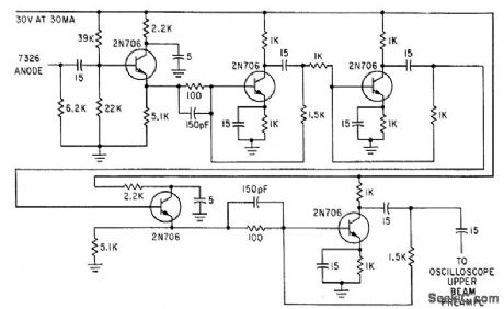
Used between type 7326 photomultiplier and dualbeam oscilloscope in receiver of optical ranging system. Voltage gain is 100 for output dynamic range of 1.5 V, but noise figure is only about 14 db.-M. L. Stitch, E. J. Woodbury and J. H. Morse, Optical Ranging System Uses Laser Transmitter, Electronics, 34:16, p 51-53. (View)
View full Circuit Diagram | Comments | Reading(755)
PICOAMMETER_CIRCUIT
Published:2009/7/7 23:12:00 Author:May
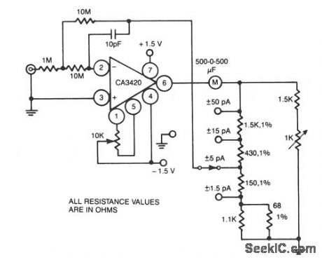
This circuit uses the exceptionally low input current 0.1 pA of the CA3420 BiMOS op amp. With only a single 10-MΩ resistor, the circuit covers the range from ± 50 pA to a maximum full-scale sensi-tivity of ±1.5 pA. (View)
View full Circuit Diagram | Comments | Reading(0)
CURRENT_MONITOR_AND_ALARM
Published:2009/7/7 23:11:00 Author:May
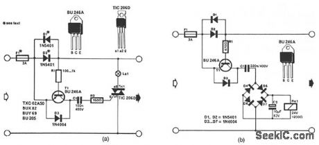
The circuit in Fig. 56-11a lights the signal lamp upon detecting a line current consumption of more than 5 mA, and handles currents of several amperes with appropriate diodes fitted in the Dl and D2 positions. Transistor T1 is switched on when the drop across D1/D2 exceeds a certain level. Diodes from the well-known 1N400x series can be used for currents of up to 1 A, while 1N540x types are rated for up to 3 A. Fuse Fl should suit the particular application.The circuit in Fig. 56-11b is a current-triggered alarm. Rectifier bridge D4 through D7 can only provide the coil voltage for Rel when the current through D1/D2 exceeds a certain level, because then series capacitor C1 passes the alternating main current. Capacitor C1 needs to suit the sensitivity of the relay coil. This is readily effected by connecting capacitors in parallel until the coil voltage is high enough for the relay to operate reliably. (View)
View full Circuit Diagram | Comments | Reading(1266)
BIPOLAR_ANALOG_TWO_QUADRANT
Published:2009/7/7 23:11:00 Author:May
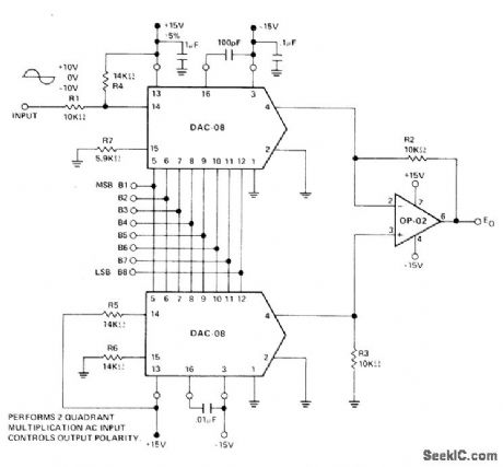
Bipolar reference voltage for upper Precision Monolithics DAC-08 D/A converter modulates reference current by ±1.0 mA around quiescent current of 1.1 mA. Lower DAC-08 has same 1.1-mA reference current and effectively subtracts out quiescent 1.1 mA of upper reference current at all input codes since voltage across R3 varies between -10 V and 0 V. Output voltage E0 is thus product of digital input word and bipolar analog reference voltage.-J. Schoeff and D. Soderquist, Differential and Multiplying Digital to Analog Converter Applications, Precision Monolithics, Santa Clara, CA, 1976, AN-19, p 3. (View)
View full Circuit Diagram | Comments | Reading(1691)
LOW_NOISE_TAPE_RECORDER_PREAMP
Published:2009/7/21 6:24:00 Author:Jessie
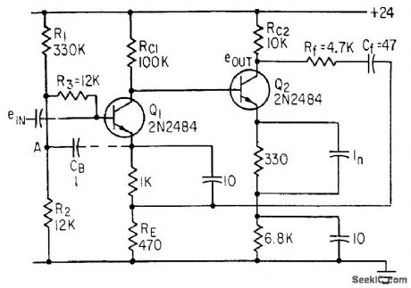
Closed-loop gain is 20 db from 100 cps to nearly 8 Mc for source impedance of 1,000 to 6,000 ohms.-J. J. Rado, Designing Input Circuits with Lowest Possible Noise, Electronics, 36:31, p 46-49. (View)
View full Circuit Diagram | Comments | Reading(1039)
ELECTROSTATIC_DETECTOR
Published:2009/7/7 23:09:00 Author:May
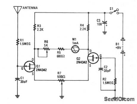
The heart of the electroscope is the two junction FETs Q1 and Q2 connected in a balanced-bridge circuit. The gate input of Q1 is connected to the wire pick-up antenna, while Q2's gate is tied to the circuit's common ground through R2. That type of bridge circuit offers excellent temperature stability; therefore, Q1 is allowed to operate in an open-gate configuration. Potentiometer R7 is used to balance the bridge circuit, and R6 sets the maximum meter swing. Capacitors C1 and C2 help to reduce the 60-Hz pickup and add to the short-term stability of the circuit. (View)
View full Circuit Diagram | Comments | Reading(2310)
QRP_SWR_BRIDGE
Published:2009/7/7 23:08:00 Author:May
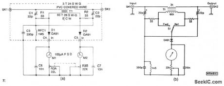
The design shown is a simple unit for QRP operation on all authorized frequencies up to 30 MHz, based on a toroidal transformer T1. The secondary winding of T1 samples a small amount of rf power, both forward and reflected, which is divided by the bridge circuit and rectified by diodes D1and D2. Forward and reflected readings are obtained simultaneously on the two meters Ml and M2, and the bridge is matched and balanced at the required load impedance by C1 and C2. See Fig. 56-9b for an alternative, less expensive, single meter version. The bridge also measure forward power. (View)
View full Circuit Diagram | Comments | Reading(1408)
| Pages:970/2234 At 20961962963964965966967968969970971972973974975976977978979980Under 20 |
Circuit Categories
power supply circuit
Amplifier Circuit
Basic Circuit
LED and Light Circuit
Sensor Circuit
Signal Processing
Electrical Equipment Circuit
Control Circuit
Remote Control Circuit
A/D-D/A Converter Circuit
Audio Circuit
Measuring and Test Circuit
Communication Circuit
Computer-Related Circuit
555 Circuit
Automotive Circuit
Repairing Circuit