
Circuit Diagram
Index 964
OVERSHOOT_COMPENSATION
Published:2009/7/8 3:24:00 Author:May
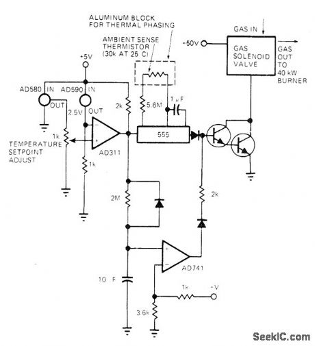
Used to control temperature of industrial gas-fired heater having very high thermal capacity. When AD311 opamp comparator trips at set-point temperature, 555 mono makes transistors turn on gas solenoid and light burner. When mono times out, burner goes off regardless of opamp output condition, Time constant of 555 compensates for lags in system by turning off heater before AD590 sensor reaches cutoff value, Thermistor across 555 mono compensates for changes in ambient temperature. During start-up, AD741 opamp and associated circuit effectively by-passes mono, and also turns on heater if mono fails to fire for any reason.-J. Williams, Designer's Guide to: Temperature Control, EDN Magazine, June 20, 1977, p 87-95.
(View)
View full Circuit Diagram | Comments | Reading(1243)
Variable_speed_control_for_induction_motors_1
Published:2009/7/21 5:57:00 Author:Jessie


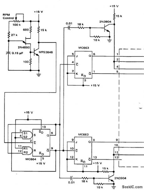
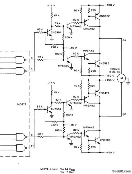
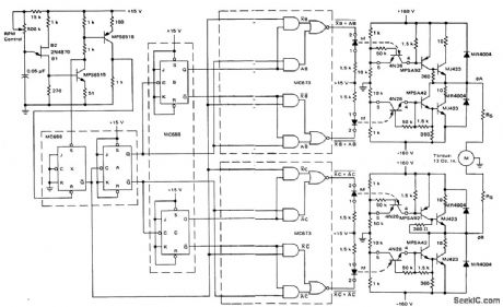

Variable speed control for induction motors (courtesy Motorola Semiconductor Products Inc.). (View)
View full Circuit Diagram | Comments | Reading(892)
ANTICIPATING_CONTROLLER
Published:2009/7/8 3:23:00 Author:May
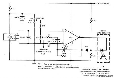
Circuit adds selected amount of phase Ieading signal to notmal amplified output of National LX5700 temperature sensorto compensate at least partially for sensing Iags. DC gain of LM216 opamp is set at t0 by 10-megohm and 100-megohm resistors to give opamp output of 1 V/°C. Output of opamp energizes optoisolator that feeds conventional temperature control system.-P. Lefferts, A New Interfacing Concept; the Monolithic Temperature Transducer, National Semiconductor, Santa Clara, CA, 1975, AN-132, p 7. (View)
View full Circuit Diagram | Comments | Reading(710)
5000_V_D_C_FROM_26_V_D_C
Published:2009/7/21 5:56:00 Author:Jessie
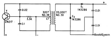
Uses transistor as sinusoidal oscillator. Voltage-doubling capacitors keep ripple below 0.01%.-R. D. Morrow, Inexpensive Converter Gives 5,000 Volts D-C, Electronics, 35:28, p 54. (View)
View full Circuit Diagram | Comments | Reading(609)
THERMISTOR_BRIDGE
Published:2009/7/8 3:21:00 Author:May
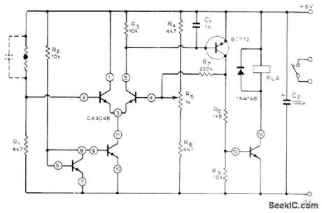
Bridge is formed by thermistor with R1, R4, R5, and R6. Unbalance is sensed by CA3046 IC having two matched pairs of transistors, with additional output transistor in IC. Positive feedback through R7 prevents chatter as switching point is approached. R5 sets switching temperature precisely. Relay comes on when temperature drops below pre determined point; for opposite function, reverse positions of thermistor and R1. Value of R1 is chosen to give approximately the desired control point.-D. E. Waddington, Thermistor Controlled Thermostat, Wireless World, July 1976, p 36.
(View)
View full Circuit Diagram | Comments | Reading(1179)
0000033℃_CHOPPER_STABILIZED_OVEN_CONTROL
Published:2009/7/8 3:18:00 Author:May
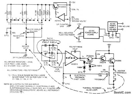
Uses chopper-stabilization techniques to provide ultimate in temperature control for laboratory oven. Multiranging bridge accommodates sensols from 10 ohms to 1 megohm, with Kelvin-Valley divider being used to dial sensor resistance control point directly to five digits. Use of floating power supply for bridge allows single-ended noninverting chopper-stabilized AD741J amplifier to take differential measurement and eliminates commonmode voltage elror. Passive 60-Hz notoh fittel eliminates pickup noise at input of AD261K amplifier which in turn feeds 2N2222A transistor driving Darlington pair that provides up to 30 V across heater of oven. Article also gives circuit of 30-V regulated supply required for output transistors.-J. Williams, Designer's Guide to: Tempelature Contlol, EDN Magazine, June 20, 1977, p 87-95.
(View)
View full Circuit Diagram | Comments | Reading(1077)
8_bit_storage_register
Published:2009/7/21 21:24:00 Author:Jessie
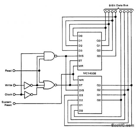
8-bit storage register (courtesy Motorola Semiconductor Products Inc.). (View)
View full Circuit Diagram | Comments | Reading(2546)
SSB_MONITOR
Published:2009/7/21 21:24:00 Author:Jessie
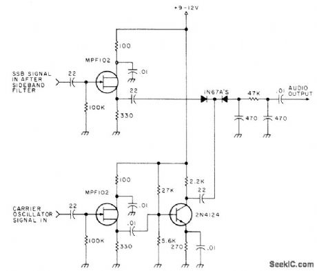
Requires two connections to SSB transmitter, at output of carrier oscillator and at output of sideband filter. FET isolation stages for each connection feed 2N4124 product detector that gives audio signal for monitoring directly with headphones or for feeding AF amplifier driving loudspeaker,-Clean Up Your Act,73 Magazine.Jan 1978,p136-137. (View)
View full Circuit Diagram | Comments | Reading(1118)
Tape_recorder_position_indicator_controller_using_an_ICM7217A_28_pin_DIP
Published:2009/7/21 21:23:00 Author:Jessie
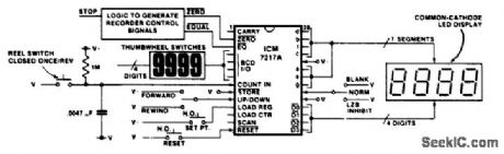
Tape recorder position indicator/controller using an ICM7217A 28-pin DIP. This circuit employs the up/down feature of the ICM7217 to keep track of the tape position. The not-equal and not-zero outputs can be used to control the recorder. To make the recorder stop at a particular point on the tape, the register can be set with the stop point and the equal output used to stop the recorder, either on fast forward, play or rewind. To have the recorder stop before the tape comes free of the reel on rewind a leader should be used. Resetting the counter at the starting point of the tape a few feet from the end of the leader allows the zero output to be used to stop the recorder on rewind. The 1 M resistor and 0.0047μF capacitor on the count input provides a time constant of about 5 ms to debounce the reel switch (courtesy Intersil, Inc.). (View)
View full Circuit Diagram | Comments | Reading(2145)
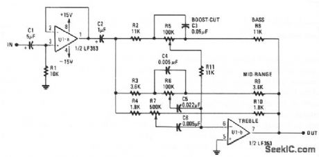
THREE_BAND_ACTIVE_TONE_CONTROL
Published:2009/7/8 3:17:00 Author:May
View full Circuit Diagram | Comments | Reading(3966)
160_MC_15_W_POWER_AMPLIFIER
Published:2009/7/21 7:38:00 Author:Jessie
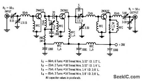
Simple three-stage r-f power transistor circuit provides 30.5 db power gain with efficiency of 62%, on 28-v supply.-Solid-State Power Amplifier Design (Motorola ad), Electronics, 39:14, p 48-49. (View)
View full Circuit Diagram | Comments | Reading(1)
TEN_BAND_OCTAVE_EQUALIZER
Published:2009/7/8 3:16:00 Author:May
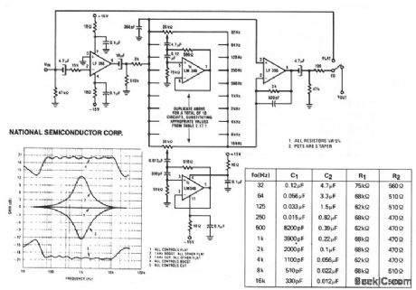
A series of active rf filters using National LM348IC comprises a ten-band graphic equalizer. C1, C2, R1, and R2 should be at least 10% with 5% preferred tolerances. (View)
View full Circuit Diagram | Comments | Reading(1868)
TUNNEL_DIODE_WIRELESS_MIKE
Published:2009/7/21 7:36:00 Author:Jessie
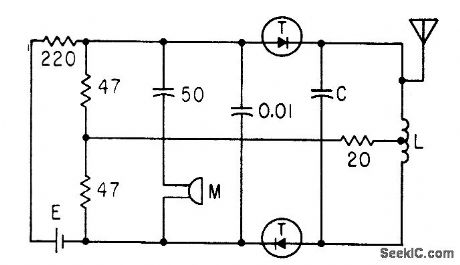
Two cascaded 2-ma germanium tunnel diodes serving as cascade oscillator and 90-Mc f-m modulator give range of over 100 feet. Coil L is about 5 microhenrys, with five turns a quarter-inch in diameter and half an inch long.C is 24 pf.-W. Ko, Tunnel Diode F.M Wireless Microphone, Electronics, 33:47, p 93-95. (View)
View full Circuit Diagram | Comments | Reading(1310)
144_175_MHz_80_W_SINGLE_STAGE_FM_MOBlLE
Published:2009/7/8 3:15:00 Author:May
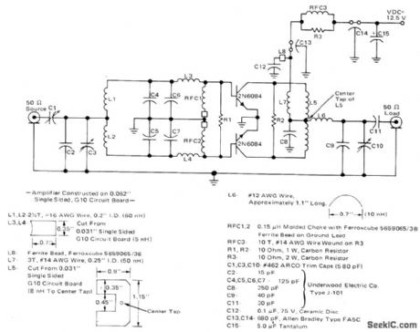
Provides rated outputinto 50-ohm load,Can withstand open and shorted loads for all load phase angles without transistor damage Uses Motorola 2N6084 land,mobile transistors optimized for 12.5-V FM operation. Transistors are used in parallel with single-ended input and output, isolated from each other by signal-split-ting coils.—J. Hatchett, VHF Power Amplifiers Using Paralleled Output Transistors, Motorola, Phoenix, AZ, 1972, AN-585, p 2. (View)
View full Circuit Diagram | Comments | Reading(2367)
TEMPERATURE_DIFFERENCE_DETECTOR
Published:2009/7/8 3:14:00 Author:May
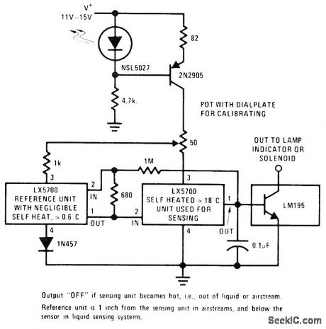
Pair of National LX5700 temperature transducers delivers output voltage proportional to temperature difference between transducers, as required for sensing temperature gradient in chemieal processes, detecting failure of cooling fan, detecting movement of cooling oil, and monitoring other heat-absorbing phenomena.With sensing transducer in hot condition (out of liquid or in still air for 2 min), adjust 50-ohm pot to setting that just turnspower output off. Next, with transducer in cool condition (in liquid or in moving air for 30 s), find setting that just tums output on. These settings overlap, but final setting between them will provide stable operation.-P. Lefferts, A New Interfacing Concept; the Monolithic Temperature Transducer, National Semiconductor, Santa Clara, CA, 1975, AN-132, p 7.
(View)
View full Circuit Diagram | Comments | Reading(1250)
IC_PREAMPLIFIER_TONE_CONTROL
Published:2009/7/8 3:12:00 Author:May
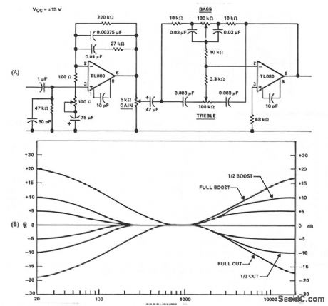
The circuit is a form of the so-called Americanized version of the Baxandall negative-feedback tone control. At very low frequencies, the reactance of the capacitor is large enough that they might be considered open circuits, and the gain is controlled by the bass potentiometer. At low to middle frequencies, the reactance of the 0.03-μF capacitors decreases at the rate of 6 dB/octave, and is in parallel with the 200-KΩ potentiometer; so the effective impedance is reduced correspondingly, thereby reducing the gain. This process continues until the 10-KΩ resistors, which are in series with the bass pot, become dominant and the gain levels off at unity. The action of treble circuit is smaller and becomes effective when the reactance of the 0.003- μF capacitors becomes minimal. This complete tone control is in the negative feedback loop of the TL080. Figure B shows the bass and treble tone control response. (View)
View full Circuit Diagram | Comments | Reading(4369)
Triac_motor_speed_control_with_feedback
Published:2009/7/21 7:35:00 Author:Jessie
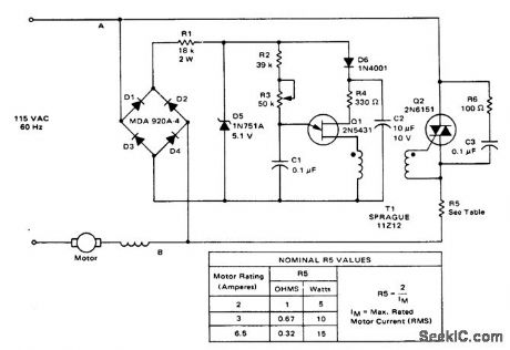
Triac motor speed control with feedback (courtesy Motorola Semiconductor Products Inc.). (View)
View full Circuit Diagram | Comments | Reading(2130)
TV_video_IF_output_and_detector_with_AFT_and_sound_take_off_output
Published:2009/7/21 7:35:00 Author:Jessie
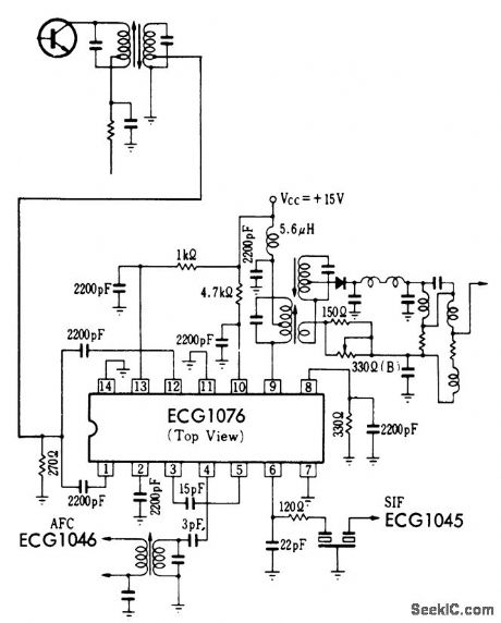
TV video IF output and detector with AFT and sound take-off output. All coils and transformers are standard and can be purchased at a local electronic parts jobber (Merit or Miller components). Sound output at 4.5 MHz is typically 300 mV PMS. AFT output is typically 210 mV PMS at atest frequency of 57 MHz. Typical voltage gain for the video IF is 36 dB (courtesy GTE Sylvania Incorporated). (View)
View full Circuit Diagram | Comments | Reading(796)
THERMAL_CYCLER
Published:2009/7/8 3:12:00 Author:May
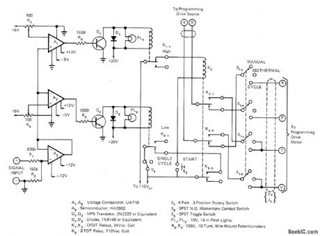
Circuit allows operator to preselect uipper and lower temperature limits for controller used in determining effect of continuous thermal cycling on properties of materials.Switching arrangement gives choice of ranging from manual to fully automatic continuous cycling.Operation of programming drive motor is controlled by continuous of relay K3.When relay is energized, motor runs in forwardd irection to increase temperature;when deenergized, motor is reversed. Condition of K3 tinuous depends on which of limit relays K1 or K2 was most recentiy energized . Control circuit samples output of temperature programmer; this DC input signal is reduced to 5 V maximum by R1-R2 and amplified by voltage follower A3 Signal is then compared in A1 and A2 to continuously variable reference voltage from 0 to 5 V preselected by 10-turn pots R3and R4. Q1 is cut off when input is below reference. When input exceeds reference, Q1 goes on and energizes upper-limit relay K1 Article gives initial setup procedure.-W.J. Dobbin, Variable Limit Switch Permits Hands-Off Equipment Cycling,EDN Magazine, Jan, 20, 1973, p 66-67.
(View)
View full Circuit Diagram | Comments | Reading(871)
MEASURING_ANTENNA_RADIATION_PATTERN
Published:2009/7/21 7:35:00 Author:Jessie
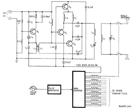
Eight transmitters, towed as group around ground antenna by airplane, hove frequencies spaced throughout bandwidth of antenna under test, from 2 to 50 Mc. Pulse-controlled ring counter switches transmitters up to 40 times per second. All transistors are type 2N3053.-C. Barnes, Transmitters Towed Through Air Test Antenna's Radiation Pattern, Electronics, 38:21, p 96-101.
(View)
View full Circuit Diagram | Comments | Reading(990)
| Pages:964/2234 At 20961962963964965966967968969970971972973974975976977978979980Under 20 |
Circuit Categories
power supply circuit
Amplifier Circuit
Basic Circuit
LED and Light Circuit
Sensor Circuit
Signal Processing
Electrical Equipment Circuit
Control Circuit
Remote Control Circuit
A/D-D/A Converter Circuit
Audio Circuit
Measuring and Test Circuit
Communication Circuit
Computer-Related Circuit
555 Circuit
Automotive Circuit
Repairing Circuit