
Circuit Diagram
Index 961
50-MHz_TRIGGER
Published:2009/7/8 4:20:00 Author:May
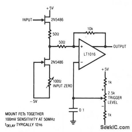
This has a stable trigger 100 mV sensitivity at 50 MHz. The FETs comprise a simple high-speed buffer and the LT1016 compares the buffer's out-put to the potential at the trigger level potentiometer, which can be of either polarity. The 10-KΩ resistor provides hysteresis, eliminating chattering caused by noisy input signals. To calibrate this circuit, ground the input and adjust the input zero control for 0 V at Q2's drain terminal. (View)
View full Circuit Diagram | Comments | Reading(709)
Triac_trigger_using_an_LM3909_chip
Published:2009/7/21 5:13:00 Author:Jessie
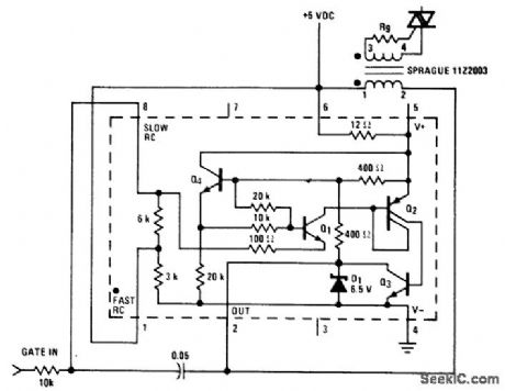
Triac trigger using an LM3909 chip. This circuit operates from a 5-volt logic supply and provides gate trigger pulses of up to 200 mA. The LM3909 provides a 10μs pulse at about a 7 kHz rate. This is not the synchronized zero crossing type since the first trigger could occur at any time; however, the repetition rate is such that after the first cycle, a triac is triggered within 8 volts of zero with a resistive load and a 115-volt AC line. The Sprague transformer provides 2-to-1 stepup (courtesy National Semiconductor Corporation). (View)
View full Circuit Diagram | Comments | Reading(804)
IF_WITH_NOISE_BLANKER
Published:2009/7/8 4:19:00 Author:May

Addition of BFO andnoise blankerto 455-kHzIF amplifier gives setupfor testing new tuners and front ends Two methods of coupling into ampliier are shown.LM373H IC with two Murata SFD-455D ceramic filters fulfills requirements for IF amρlifer,delector,and AGC functions.-R.Megirian,Design Ideas for Miniature Communications Receivers,Ham Radio,April 1976,p 18-25. (View)
View full Circuit Diagram | Comments | Reading(2657)
Motor_control_circuitry_using_3650_optical_isolation_amplifiers
Published:2009/7/21 5:12:00 Author:Jessie
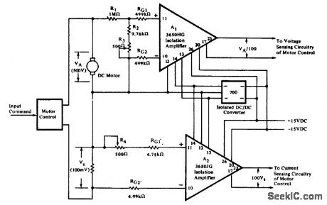
Motor control circuitry using 3650 optical isolation amplifiers (courtesy Burr-Brown Research Corporation). (View)
View full Circuit Diagram | Comments | Reading(671)
BAR_CODE_SCANNER
Published:2009/7/8 4:19:00 Author:May

The circuit illustrates a method of interfacing a HEDS-1000 emitter-detector pair with a HA-5144 for use as a bar-code scanner circuit. The HA-5144 is used as an amplifier system which converts the bar and space widths of the printed bar code into a pulse-width modulated digitA1 signal. Amplifier A1 is used to amplify the current output of the detector. The output of A1 is passed to two precision peak-detector circuits which detect the positive and negative peaks of the received signal. Amplifier A4 is used as a comparator whose reference is maintained at the midpoint of the peak-to-peak signA1 by resistors R5 and R6. This provides a more accurate edge detection and less ambiguity in bar width. Amplifier A5 is used as an optionA1 noise gate which only allows data to pass through the gate when the peak-to-peak modulation sign A1 is larger than one diode drop. This circuit is operated by a single supply voltage with low-power consumption which makes it ideal for battery-operated data entry systems. (View)
View full Circuit Diagram | Comments | Reading(3689)
5_KV_A_F_PENTODE_OSCILLATOR_CRT_SUPPLY
Published:2009/7/21 5:10:00 Author:Jessie

Pentode audio oscillator uses simplified circuit to furnish only second anode potential for crt. –NBS, Handbook Preferred Circuits Navy Aeronautical Electronic Equipment, Vol.1, Electron Tube Circuits, 1963, p N14-4. (View)
View full Circuit Diagram | Comments | Reading(718)
FLAME_IGNITOR
Published:2009/7/8 4:17:00 Author:May
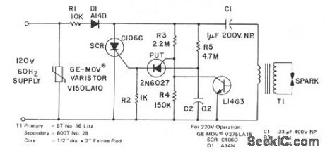
The spark developed by the circuit is suitable for a gas ignitor. Capacitor C1 is charged through R1 and D1 toward peak line voltage. C2 is simultaneously being charged at a slower rate through R5. When the charge on C2 is sufficient to trigger the PUT, the SCR is triggered on, providing a rapid discharge path for C1 through the transformer primary. The SCR is triggered about 20 times per second with the component values shown. The L14G3 serves as a flame sensor. When ignition is achieved and sensed by the photodetector, the low VCE prevents further SCR triggering. (View)
View full Circuit Diagram | Comments | Reading(1054)
Color_TV_subcarrier_generator_uslng_an_ECG1105_16_pin_DIP
Published:2009/7/21 5:10:00 Author:Jessie

Color TV subcarrier generator uslng an ECG1105 16-pin DIP.The ECG1105 consists of a keyed APC,an ACC,a killer detector amplifier,a burst amplifierand a subcarrier amplitier(courtesy GTE Sytvania Incorporated). (View)
View full Circuit Diagram | Comments | Reading(768)
BURST_POWER_CONTROL
Published:2009/7/8 4:15:00 Author:May

Industrial applications sometimes require that power be only briefly applied to a load following the closure of a switch, such as a microswitch or foot switch. The load could be a heating element for use in sealing plastic bags, a dc motor that is indexed or stepped with each application of power, or a dc solenoid which is to be energized for a brief time-for example, a staple gun.
The phase angle at which the SCR triggers on is determined by the charging rate of C2 through R7 and potentiometer R8. When the breakover voltage of the gate triggering device, a silicon unilateral switch, is reached, the SCR turns on. The average dc voltage to the load is determined by the setting of R8.
(View)
View full Circuit Diagram | Comments | Reading(1268)
SIMPLE_LOW_COST_RF_SWITCH
Published:2009/7/8 4:13:00 Author:May
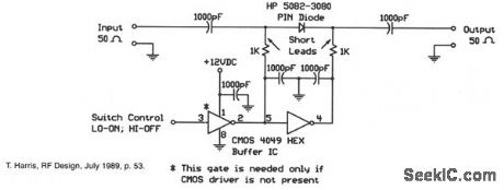
When the digital logic level at the control input is low, the PIN diode is forward-biased by the CMOS gates. The two 1-KΩ bias resistors limit this current to the PIN diode's safe forward current limit. In this state, the switch is on. When the control input is high, the diode is reverse-biased and the switch is off.This switch is well-suited for electronically steered antenna arrays, multiple path switching, and other applications requiring small, low-cost rf switches. This particular design was used in a four-pole rotary switch for a Doppler-shift radio direction-finder operating at 144 MHz.
(View)
View full Circuit Diagram | Comments | Reading(955)
ACID_RAIN_MONITOR
Published:2009/7/8 4:11:00 Author:May
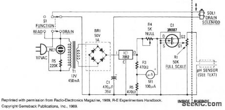
A simple bridge rectifier and a 12-V regulator powers the MOSFET sensing circuit. The unregulated output of the bridge rectifier operates the drain solenoid via switch S1. The sensor itself is built from two electrodes: one made of copper, the other of lead. In combination with the liquid trapped by the sensor, the electrodes form a miniature lead/acid cell whose output is amplifted by MOSFET Q1. The maximum output produced by our prototype cell was about 50 μA.MOSFET Q1 serves as the fourth leg of a Wheatstone bridge. When sensed acidity causes the sensor to generate a voltage, Q1 turns on slightly, so its drain-to-source resistance decreases. That resistance variation causes an imbalance in the bridge, and that imbalance is indicated by meter M1. (View)
View full Circuit Diagram | Comments | Reading(0)
POSITIVE_INPUT_NEGATIVE_OUTPUT_OHARGE_PUMP
Published:2009/7/8 4:10:00 Author:May
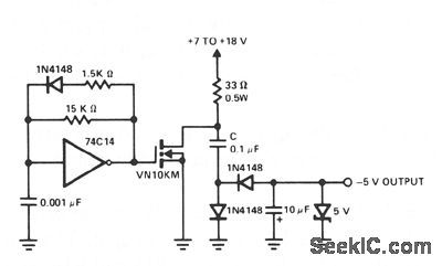
A charge pump is a simple means of generating a low-power voltage supply of opposite polarity from the main supply. The 74C14 IC is a self-oscil-lating driver for the MOSFET power switch. It produces a pulse width of 6.5 prs at a repetition frequency of 100 kHz. When the MOSFET device is off, capacitor C is charged to the positive supply.When the power through the MOSFET switches on, C delivers a negative voltage through the series diode to the output. The zener serves as a dissipative regulator. Because the MOSFET switches fast, operation at high frequencies allows the capacitors in the system to be small. (View)
View full Circuit Diagram | Comments | Reading(934)
AM_FM_WITH_AGC_
Published:2009/7/8 4:10:00 Author:May

Operates from single +15 V supply. Standard 455-kHz IF is used for AM to feed 1N34A diode detector. One output of MC1350 is used for FM signal component and the other for AM component. External transistor is needed because MC1350 requires up to 0.2 mA of AGC drive and this is more than can be furnished by diode detector.- Integrated Circuit IF Amplifiers for AM/FM and FM Radios, Motorola,Phoenix, AZ, 1975, AN-543A, p 10.
(View)
View full Circuit Diagram | Comments | Reading(3097)
GEIGER_MULLER_SUPPLY
Published:2009/7/21 5:43:00 Author:Jessie
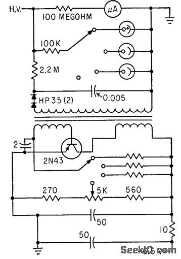
Uses blocking oscillator to provide three stabilized levels of high voltage, at 900, 1,000, and 1,100 V, for G-M tube. Corona discharge tubes are switched in to provide regulation.-F. E. Armstrong, Battery Powered Portable Scaler, Electronics, 33:19, p 74-75. (View)
View full Circuit Diagram | Comments | Reading(1045)
Thyrister_half_wave_control_circuit_with_UJT_trigger_designed_for_a_600_ohm_load
Published:2009/7/21 5:42:00 Author:Jessie
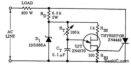
Thyrister half-wave control circuit with UJT trigger designed for a 600-ohm load (courtesy Motorola Semiconductor Products Inc.). (View)
View full Circuit Diagram | Comments | Reading(2198)
ELECTRONIC_MUSIC
Published:2009/7/8 4:09:00 Author:May
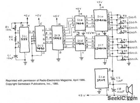
IC1, a 555 timer, is set up as an astable multivibrator to produce the signal that triggers IC2, a 7490 decade counter. That IC, in turn, produces a BCD output that is fed to IC3, a 7445 BCD-to-decimal decoder/driver. IC3's output is inverted by two hex inverters, IC4 and IC5. The outputs of IC4 and IC5 are inputted to control pins on IC6 and IC7, CD4016 CMOS quad bilateral switches. As those switches open and close, different resistances (as set by potentiometers R3 through R10) are inserted into the sound-generating circuit made from IC8. The frequency at the outputs of IC6 and IC7 are adjusted to various rates, using potentiometers R3 through R10, to produce the desired tones. Capacitors can be placed in series with the potentiometers to produce a sloping sound instead of a straight tone. The negative-going output signals of IC6 and IC7 are fed through a common bus to pin 8 of IC8. (View)
View full Circuit Diagram | Comments | Reading(2160)
Plug_in_speed_control_for_tools_and_appliances
Published:2009/7/21 5:41:00 Author:Jessie
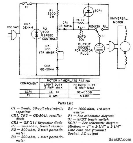
Plug-in speed control for tools and appliances. Do not use this control on motors without commutators (courtesy General Electric Company). (View)
View full Circuit Diagram | Comments | Reading(812)
BREATH_ALERT_ALCOHOL_TESTER
Published:2009/7/8 4:07:00 Author:May

When power is applied to the circuit, the heater coil in the sensor is energized by the 5-V output of IC5, a 7805 voltage regulator. Breathing into the sensor with alcohol on your breath will lower the sensor's resistance; consequently, the input voltage to the detector circuit, will change. The detector circuit consists of quad op amp, IC2 and its associated circuitry. All sections of the detector circuit are calibrated via R3 and R4, and the inputs to each section are controlled by the voltage-divider network R21 through R23.As each section is triggered, the outputs decrease, and sample-and-hold circuits, IC3 and IC4, will latch onto the highest input value and drive the appropriate LED. The different colored LEDs represent alcohol levels front 0 to 0.16%.
If the level of alcohol is above the legal limit, or 0.16%, part of another quad op amp, IC1d, will turn on both the optional buzzer and LED5. That is an indication of a high level of alcohol present in your blood, and you definitely should not drive.
After a test is taken,the sensor takes a few seconds to ready itself for another test. When the sensor is ready, its input to IC1b, adjusted via R2 to a threshold of 0.5 V, causes LED4 (ready) to light. That, in turn, causes IC1c to reset the rest of the circuitry. The last section of IC1 is biased via R15 and R16, and used to indicate a low-battery condition-when the battery voltage drops below 6.8 V-which could result in an inaccurate breath test. (View)
View full Circuit Diagram | Comments | Reading(2959)
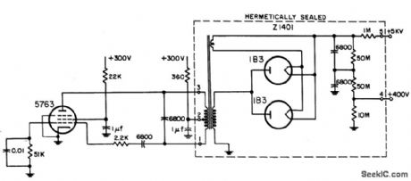
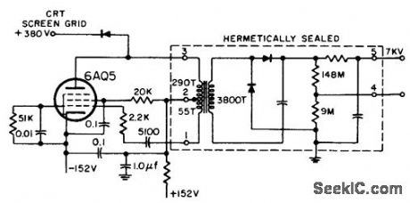
7_KV_A_F_PENTODE_OSCILLATOR_CRT_SUPPLY
Published:2009/7/21 5:40:00 Author:Jessie

Pentode feeds hermetically sealed unit containing transformer, paralleled 1B3's, and filter.-NBS, Handbook Preferred Circuits Navy Aeronautical Electronic Equipment, Vol. 1, Electron Tube Circuits, 1963, p N14-4. (View)
View full Circuit Diagram | Comments | Reading(753)
7_KV_OSCILLATOR_TYPE_CRT_SUPPLY
Published:2009/7/21 5:38:00 Author:Jessie
Audio oscillator provides screen-grid voltage for crt directly and second-anode voltage through high-voltage transformer and rectifier-filter.-NBS, Handbook Preferred Circuits Navy Aeronautical Electronic Equipment, Vol. 1, Electron Tube Circuits, 1963, p N14-2. (View)
View full Circuit Diagram | Comments | Reading(721)
| Pages:961/2234 At 20961962963964965966967968969970971972973974975976977978979980Under 20 |
Circuit Categories
power supply circuit
Amplifier Circuit
Basic Circuit
LED and Light Circuit
Sensor Circuit
Signal Processing
Electrical Equipment Circuit
Control Circuit
Remote Control Circuit
A/D-D/A Converter Circuit
Audio Circuit
Measuring and Test Circuit
Communication Circuit
Computer-Related Circuit
555 Circuit
Automotive Circuit
Repairing Circuit