
Circuit Diagram
Index 968
_DIGITAL_FREQUENCY_METER
Published:2009/7/8 1:48:00 Author:May
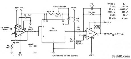
The circuit converts frequency to voltage by taking the average dc value of the pulses from the 74121 monostable multivibrator. The one shot is triggered by the positive-going ac signal at the input of the 529 comparator. The amplifier acts as a dc filter, and also provides zeroing. This circuit will maintain an accuracy of 2% over 5 decades of range. The input signal to the comparator should be greater than 0.1 V pk-pk, and less than 12 V pk-pk for proper operation. (View)
View full Circuit Diagram | Comments | Reading(2229)
CRYSTAL_OVEN_CONTROL
Published:2009/7/8 1:47:00 Author:May
Unbalance voltage produced in thermistor bridge when temperature drops below set point is sensed by differential opamp that feeds buffer Q1 and power amplifier Q2, Power dissipated in Q2 and its load R11 heats oven. Thermistor R4 has nominal resistance of 3600 ohms at 50℃ (GE 1D53 or National Lead 1D053). Voltage divider R1-R2 reduces U1 input to safe Ievel and makes thermistor operate at low current, minimizing self-heating effects. All arms of thermistor bridge except R7 (vemier temperature ad justment) are in oven.-R. Silberstein, An Experimental Frequency Standard Using ICs, QST, Sept. 1974, p 14-21 and 167.
(View)
View full Circuit Diagram | Comments | Reading(821)
LOW_POWER_PARALLEL_TRANSISTOR_OUTPUT
Published:2009/7/21 7:41:00 Author:Jessie
Conventional transistor arrangement provides up to 2 w output with power gain of 10 db. Chief advantage is simplicity.-W.A. Rheinfelder, Choosing the Best Transmitter Output Stage, EEE, 11:10, p 48-53. (View)
View full Circuit Diagram | Comments | Reading(909)
_SCR_TESTER
Published:2009/7/8 1:46:00 Author:May
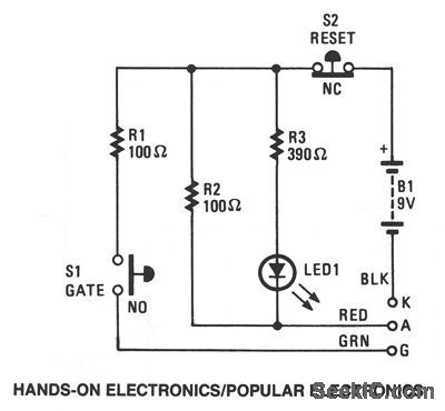
The DUT's(Device Under Test) cathode, anode, and gate are connected to the unit's K,A, and G terminals, respectively. Pressing switch S1 feeds a gate current to the DUT, which triggers it on. Resistor R1 limits the gate current to the appropriate level. Resistor R3 limits the current through the LED to about 20 mA, which, with the current through R2, results in a latching current of about 110 mA. The LED is used to monitor the latching current. If the DUT is good, once the gate is triggered with S1, the LED will remain lit, indicating that the device is conducting. To end the test, turn off the device by interrupting the latching current flow using switch S2. The LED should turn off and remain off. The preceding procedure will work with SCRs and triacs. To check LEDs and other diodes, connect the anode and cathode leads to the anode and cathode of the diode; LED1 should light.When the leads are reversed, the LED should remain off. (View)
View full Circuit Diagram | Comments | Reading(1152)
Solid_state_relay_circuit_with_input_protection_of_the_MOC3011_triac_driver
Published:2009/7/21 7:41:00 Author:Jessie

Solid-state relay circuit with input protection of the MOC3011 triac driver. The input voltage to the protection circuit can be 3 to 30 volts DC (courtesy Motorola Semiconductor Products Inc.). (View)
View full Circuit Diagram | Comments | Reading(1327)
27_MC_REMOTE_EVENT_TRANSMITTER
Published:2009/7/21 7:41:00 Author:Jessie
Gives 400-cps modulation for pulse at input A,1,400 cps for pulse at B, and 800-cps check pulses every 2 sec, for transmitting bird nigh! data to remote recorder.-P. A. Tove and J. Czekaiewski, Infrared Curtain System Detects and Counts Moving Objects, Electronics, 34:31, p 40-43. (View)
View full Circuit Diagram | Comments | Reading(699)
AUDIBLE_LOGIC_TESTER
Published:2009/7/8 1:45:00 Author:May
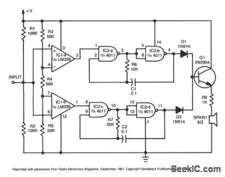
This tester provides an audible indication of the logic level of the signal presented to its input. A logic high is indicated by a high tone, a logic low is indicated by a low tone, and oscillation is indicated by an alternating tone. The input is high impedance, so it witt not load down the circuit under test. The tester can be used to troubleshoot TTL or CMOS logic. The input consists of two sections of an LM339 quad comparator. IC1a increases when the input voltage exceeds 6770 of the supply voltage. The other comparator increases when the input drops below 330/0 of the supply.
The tone generators consist of two gated astable multivibrators. The generator built around IC2a and IC2b produces the high tone. The one built around IC2c and IC2d produces the low tone. Two diodes, D1 and D2, isolate the tone-generator outputs. Transistor Q1 is used to drive a low-impedance speaker.
(View)
View full Circuit Diagram | Comments | Reading(0)
Color_TV_chroma_demodulator_with_tint_control
Published:2009/7/21 7:39:00 Author:Jessie
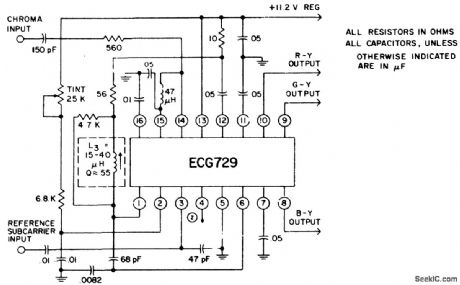
Color TV chroma demodulator with tint control. The color demodulators consist of two sets of balanced detectors that receive their reference subcarrier from the internal demodulator drive amplifiers. The chroma signal input is applied to pin 14. The chroma signal differentially drives the demodulators. The demodulation components are matrixed and DC-shifted in voltage to give R-Y, G-Y and B-Y color difference compo-nents with close DC balance and proper amplitude ratios. When the zener reference element is not used the power supply should be maintained at +11.2 volts (courtesy GTE Sylvania Incorporated). (View)
View full Circuit Diagram | Comments | Reading(1336)
DIFFERENTIAL_TO_10°F
Published:2009/7/8 1:45:00 Author:May
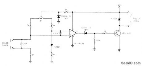
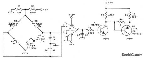
Simple circuit senses difference between temperatures of two objiects, as required for such control applications as turning on fans, turning off heaters, or opecrating mixing valves, inexpensive 1N4001 silicon diode is used as sensor; with two such diodes in resistance bridge as shown, voltage between reference and sensor diodes is applied to pins 4 and 7 of opamp. High-gain opamp is required because bridge output is only about 2mV/℃ of temperature differential. If output requires morethan about 10 mA, buffer transistor is needed.-J. Barnes, Differential-Tempera-ture Sensor is Very Inexpensive, EDN Magazine, April5, 1973, p 90-91. (View)
View full Circuit Diagram | Comments | Reading(548)
PUSH_PULL_OUTPUT_WITH_LATTICE_FILTERS
Published:2009/7/21 7:39:00 Author:Jessie
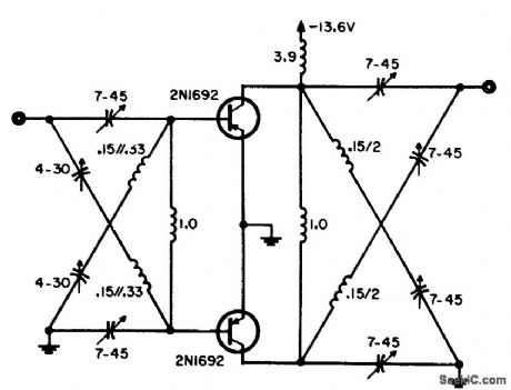
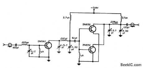
Preferred for frequencies above 30 Mc because lattice arrangement without transformers is much easier to construct and align than standard push-pull circuit.-W. A. Rheinfelder, Choosing the Best Transmitter Output Stage, EEE, 11:10, p 48-53. (View)
View full Circuit Diagram | Comments | Reading(693)
HOT_WIRE_ANEMOMETER
Published:2009/7/8 1:43:00 Author:May

View full Circuit Diagram | Comments | Reading(3287)
Remote_control_of_AC_load_using_an_MOC3011_optically_coupled_triac_driver
Published:2009/7/21 7:39:00 Author:Jessie
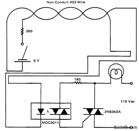
Remote control of AC load using an MOC3011 optically coupled triac driver (courtesy Motorola Semiconductor Products Inc.). (View)
View full Circuit Diagram | Comments | Reading(1227)
TEMPERATURE_REPORTING_DIGITAL_THERMOMETER
Published:2009/7/8 1:42:00 Author:May
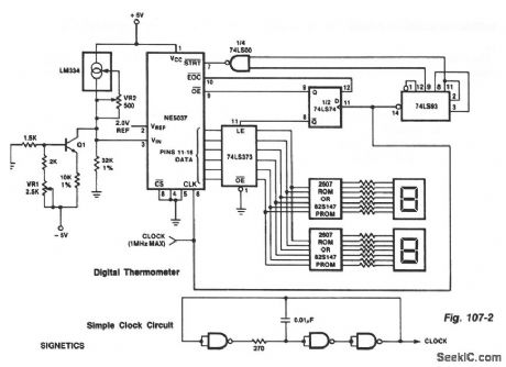
The ROMs or PROMs must have the correct code for converting the data from the NE5037-used as address for the ROMs or PROMs-to the appropriate segment driver codes. The displayed amount could easily be converted to degrees Fahrenheit, °F, by the controller of (0 - 63 °temperature sensor) or through the (P) ROMs. When doing this, a third (hundreds) digit (P)ROM and display will be needed for displaying temperatures above 99 °F. An expensive clock can be made from NAND gates or inverters as shown. (View)
View full Circuit Diagram | Comments | Reading(1287)
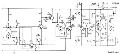
MINIATURE_F_M_TRANSMITTER
Published:2009/7/21 7:38:00 Author:Jessie
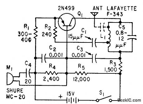
Single 2N499 transistor performs functions of r-f oscillator, frequency modulator, and audio amplifier for tiny portable transmitter having range of 200 feet. Suitable for use with public-address system.-D. E. Thomas and J. M. Klein, How to Construct a Miniature F.M Transmitter, Electronics, 32:31, p 80-81. (View)
View full Circuit Diagram | Comments | Reading(1145)
TIME_PROPORTIONAL_CONTROL
Published:2009/7/8 1:41:00 Author:May
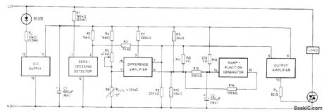
Provides synchronous ON/OFF switching of resistive load under control of temperature-sensitive bridge formed by R4, R5, and negative temperature coefficient thermistor R6 in one bridge branch, with R9 and R10 in other branch. All required function elements are included in Mullard TCA280A trigger module. Values shown are for triac requiring gate cuwent of 100 mA; for other triacs, values of Rd' Rg'and C1 may need to be changed. Proportional band can be adjusted by changing value of R12, Triac triggering coincides with zero crossings of AC line voltage.Repetition time of internally generated siwtooth is about 30 s and can be adiusted by changing C2.- TCA280A Trigger IC for Thy ristors and Triacs, Mullard, London, 1975, Technical Note 19, TP149O, p 10.
(View)
View full Circuit Diagram | Comments | Reading(973)
800_watt_triac_light_dimmer_with_silicon_bilateral_switch_SBS
Published:2009/7/21 7:38:00 Author:Jessie
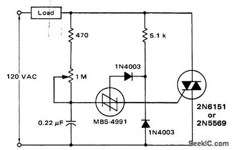
800-watt triac light dimmer with silicon bilateral switch, SBS (courtesy Motorola Semiconductor Products Inc.). (View)
View full Circuit Diagram | Comments | Reading(2448)
S_METER
Published:2009/7/8 1:41:00 Author:May
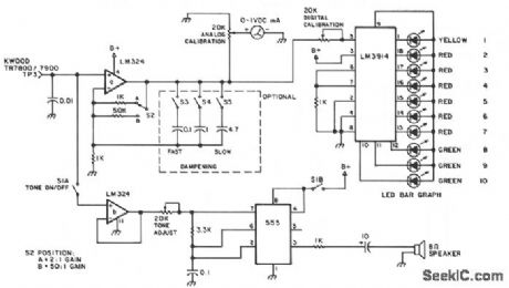
This design is for an external signal strength meter that is analog, digital, and audible for mobile trans-mitter hunters. The S meter also incorporates a gain circuit. The digital LED bar graph display has a very fast response time. The 3.3-KΩ resistor near LM3914 can be replaced with a 5-K pot to control LED brightness. The 52A position gives a 2:1 gain and the 52B position gives about a 50:1 gain. The calibration pots control the amount of meter action relative to the gain. The optional dampening circuit is used for the averaging of a transmitted signal that has modulated power or when a dip on the voice peaks occur. The capacitors can be switched one 'oy one or switched into a very slow response using 5.8 μF total capacitance.
(View)
View full Circuit Diagram | Comments | Reading(3673)
_LINE_CURRENT_MONITOR
Published:2009/7/8 1:39:00 Author:May
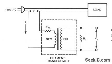
A low-cost ftlament transformer provides a linear indication of the load current in an ac line. This method causes a slight series voltage drop over a wide range of load currents. (View)
View full Circuit Diagram | Comments | Reading(761)
LOW_POWER_MAGNETIC_CURRENT_SENSOR
Published:2009/7/8 1:38:00 Author:May
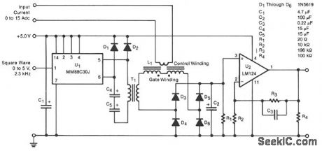
A transducer senses a direct current magnetically, providing isolation between the input and the output. The detecting-and-isolating element is a saturable reactor, in which the input current, to be measured, passes through a one-turn control coil. The transducer provides an output of 0 to 3 Vdc, an input current of 0 to 15 Adc, and consumes 22 mW at 10 Adc input.
Line driver U1 excites the saturable reactor L1 by feeding a 2.3-kHz square wave through transformer T1. The output of L1 is rectified by the bridge rectifier composed of diodes D3 through D6, then amplified by op amp U2, which has a gain of 20.
Diodes D1 and D2 commutate the reactive current fed back to the primary of T1 from L1. Without these diodes, large reactive voltage spikes on the primary would waste power and could destroy U1. Filter capacitor C1 stores the energy fed back through D1 and D2.
To minimize core losses, the core of T1 is made of an alloy of 80% nickel and 20% iron. To minimize capacitance, the primary and secondary windings are interleaved and progressively wound 350°. The primary and secondary windings consist of 408 and 660 turns, respectively, of #34 wire. (View)
View full Circuit Diagram | Comments | Reading(1248)
0001°C_ACCURACY
Published:2009/7/8 1:36:00 Author:May
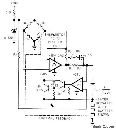
Simple design using thermistor bridge and two opamps controls temperature with high precision and has wide dynamic response as required for fast-changing ambient conditions. Circuit will not oscillate about desired temperature. Article covers design and operation of circuit in detail.-L. Accardi, Universal Temperature Controller, EDN Magazine, Dec. 1, 1972, p 53 and 55.
(View)
View full Circuit Diagram | Comments | Reading(870)
| Pages:968/2234 At 20961962963964965966967968969970971972973974975976977978979980Under 20 |
Circuit Categories
power supply circuit
Amplifier Circuit
Basic Circuit
LED and Light Circuit
Sensor Circuit
Signal Processing
Electrical Equipment Circuit
Control Circuit
Remote Control Circuit
A/D-D/A Converter Circuit
Audio Circuit
Measuring and Test Circuit
Communication Circuit
Computer-Related Circuit
555 Circuit
Automotive Circuit
Repairing Circuit