
Circuit Diagram
Index 1881
GD9815-5-the integrated microcomputer circuit of communication single door
Published:2011/5/12 21:57:00 Author:Borg | Keyword: integrated microcomputer, communication single door
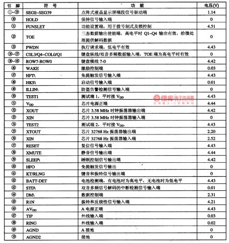
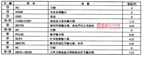
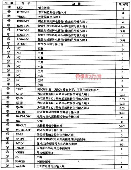
GD9815-5 is an integrated microcomputer circuit of communication single door, which is widely used in caller display phones, such as Zhongtianxin and Wondlay.1.Function features GD9815-5 contains FSK decoding circuits of caller display, while linking with two crystal oscillators from outside:one of them is 3.58MHz, and another is 32768Hz. When it is off-hook, the 32768Hz oscillator keeps the clock circuit and LED display working, by which the energy is saved.pin functions and data2. GD9815-5 is in 100-pin package of chip type.
(View)
View full Circuit Diagram | Comments | Reading(552)
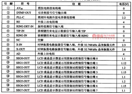
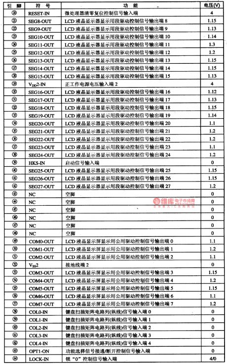
G52103-the integrated microcomputer circuit of the communication single door
Published:2011/5/12 21:56:00 Author:Borg | Keyword: integrated microcomputer circuit, single door
(View)
View full Circuit Diagram | Comments | Reading(575)
The principle function parameter circuit of Alto SC7080
Published:2011/5/12 22:00:00 Author:Borg | Keyword: parameter circuit, Alto
(View)
View full Circuit Diagram | Comments | Reading(672)
Over-temperature monitoring warning circuit diagram
Published:2011/5/12 1:23:00 Author:Rebekka | Keyword: Over-temperature monitoring warning
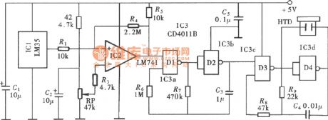
Over-temperature monitoring warning(LM35、LM741) circuit diagram is shown as above.
The over-temperature monitoring alarm circuit uses the integrated circuit temperature sensor as temperature measurement device. It only sets a maximum limiting temperature control points. When the temperature exceeds the limit temperature, the alert sounds, prompting the user to pay attention. The parts of the circuit is shown in the figure. It is composed of the temperature detector, over-temperature monitoring circuit, warning sound occurs and the output circuit. (View)
View full Circuit Diagram | Comments | Reading(1612)
μA715 dual power broadband high-speed single op amp circuit diagram
Published:2011/5/12 2:21:00 Author:Rebekka | Keyword: High-speed single op amp, dual power broadband
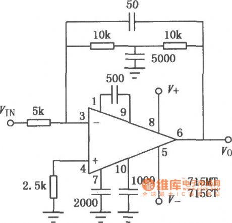
μA715 uses positive and negative dual power supply. Its conversion rate is 10 times faster than general-purpose op amps. The characteristics of μA715 is that its bandwidth is up to 6.5MHz. It is mainly used for video amplification, RF amplifier, signal generator, pulse amplification and data acquisition systems. The similar substitutions or directly models of it are CF715MT, CF715CT, CF715MD, CF715CD, CF715MJ. CF715CJ, CF715CP, F715, SG715, F053, F054, F055 and so on. The typical application circuit is shown as above. (View)
View full Circuit Diagram | Comments | Reading(1365)
Induction heating automatic control circuit diagram
Published:2011/5/12 20:04:00 Author:Rebekka | Keyword: Automatic control, Induction heating
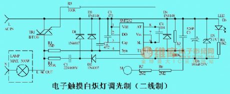
The circuit is mainly made of the specialized chip SM7232. It controls the switching and dimming incandescent lamps by human touch M-point tablets, the maximum load power is 500W.It is better to install the LED near to the touch-chip, so that it can play the role of instruction in the dark. From the human security considerations, it uses two resistors R6 and R7 . (View)
View full Circuit Diagram | Comments | Reading(3395)
μA709 dual power universal single op amp circuit diagram
Published:2011/5/12 4:03:00 Author:Rebekka | Keyword: dual power universal single op amp

μA709 is a high gain operational amplifier with the features of high input impedance, low offset voltage, peripheral frequency compensation. It is mainly used for the DC servo system, high-impedance analog voltage comparator, low instrument amplifier and so on. The similar Direct substitution models are: CFT09MT, CF? 09CT, CF709MD, CF709CD, CF709MJ, CF709CJ, CF709CP, F003, F005, CF709 and so on. μA709 typical application circuit is shown as above. (View)
View full Circuit Diagram | Comments | Reading(1305)
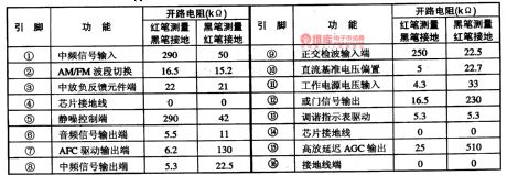
HA12413-The FM-IF integrated circuit
Published:2011/5/12 21:54:00 Author:Borg | Keyword: FM-IF, integrated circuit
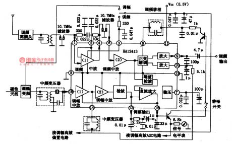
HA12413 is an FM-IF integrated circuit produced by Hitachi, Japan, which is used in all kinds of radio systems of FM stereos. 1.the HA12413 internal circuit and pin functionsHA12413 consists of INTREQ, orthogonal detection, LNA and signal instrument circuits, which characterizes with high sensitivity, low noise, low working current, few outside components and wide-range power supply voltage,etc. The IC is in 16-lead dual in-line package, whose internal circuit and typical application circuit is as shown in Figure 1-1.
(View)
View full Circuit Diagram | Comments | Reading(3208)
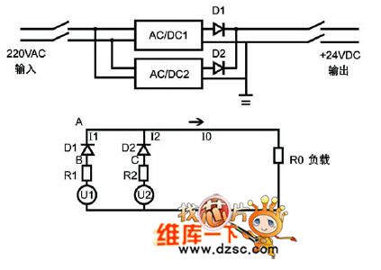
Traditional power system circuit diagram
Published:2011/5/12 21:36:00 Author:Nicole | Keyword: power system
View full Circuit Diagram | Comments | Reading(609)
Taper protection circuit diagram
Published:2011/5/12 21:38:00 Author:Nicole | Keyword: Taper protection
View full Circuit Diagram | Comments | Reading(517)
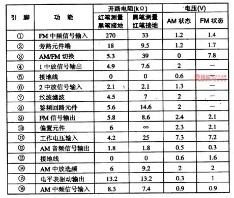
HA1137W-the FM-IF integrated circuit
Published:2011/5/12 21:38:00 Author:Borg | Keyword: FM-IF, integrated circuit
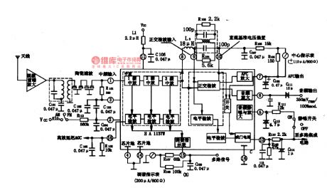
HA1137W is an FM-IF amplifier integrated circuit produced by Hitachi, Japan, which is used in HI-FI stereo tuner as FM INTREQ.
1. The internal circuit and pin functions of HA1137WHA1137W consists of sub-circuits of INTREQ, orthogonal detection, low noise preamplifier, delay high AGC, step indicator and central indicator. Its features are: high sensitivity of input amplitude, good AM impedence, low harmonic distortion, large working range and without noise in ±50KHz.
HA1137 is in 16-lead dual in-line package.
(View)
View full Circuit Diagram | Comments | Reading(4740)
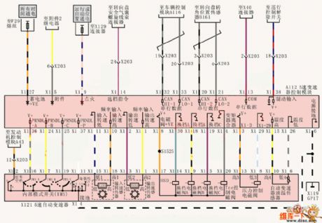
Shanghai Buick Royaum V63.6L car automatic transmission control circuit diagram(1)
Published:2011/5/12 21:42:00 Author:Nicole | Keyword: Shanghai Buick Royaum, V63.6L car, automatic transmission
View full Circuit Diagram | Comments | Reading(585)
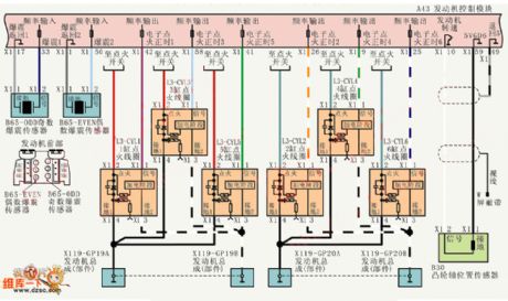
Shanghai Buick Royaum V63.6L car ignition and detonation control circuit diagram
Published:2011/5/12 21:44:00 Author:Nicole | Keyword: Shanghai Buick Royaum, V63.6L car, ignition, detonation control
View full Circuit Diagram | Comments | Reading(493)
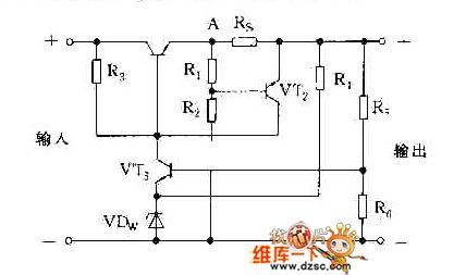
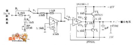
Positive and negative voltage output circuit diagram
Published:2011/5/12 21:45:00 Author:Nicole | Keyword: Positive voltage, negative voltage, output
View full Circuit Diagram | Comments | Reading(696)
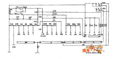
MF62 multimeter circuit diagram
Published:2011/5/12 21:48:00 Author:Nicole | Keyword: multimeter
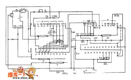
View full Circuit Diagram | Comments | Reading(712)
MF63 multimeter circuit diagram
Published:2011/5/12 21:48:00 Author:Nicole | Keyword: multimeter
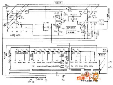
View full Circuit Diagram | Comments | Reading(1102)
MF64 multimeter circuit diagram
Published:2011/5/12 21:49:00 Author:Nicole | Keyword: multimeter
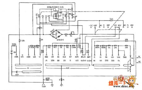
View full Circuit Diagram | Comments | Reading(865)
MF66 multimeter circuit diagram
Published:2011/5/12 21:50:00 Author:Nicole | Keyword: multimeter
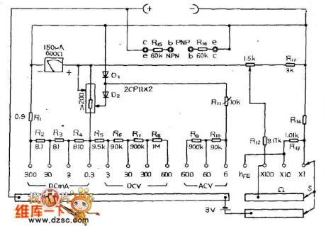
View full Circuit Diagram | Comments | Reading(2813)
MF90 multimeter circuit diagram
Published:2011/5/12 21:52:00 Author:Nicole | Keyword: multimeter
View full Circuit Diagram | Comments | Reading(761)
Electronic stethoscope(2)
Published:2011/5/10 21:07:00 Author:Nicole | Keyword: electronic stethoscope
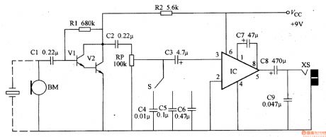
This electronic stethoscope has the feature of clear sound, it can replace the ordinary stethoscope without amplification function.
The working principle of this circuit
This electronic stethoscope circuit is composed of microphone preamplifier, tone control, volume control and power amplifier circuit, it is shown in the figure 9-137.
The preamplifier circuit is made of transistors Vl、V2 and capacitors Cl、C2, resistors Rl、R2.
RP is volume potentiometer.
The tone control circuit is composed of selection switch S and capacitors C4-C6.
The power amplifier circuit consists of integrated circuit IC and capacitors C3, C7-C9.
The microphone BM is fixed to the probe of stethoscope, it can change the sound singal such as body heart, lung, pulse into electrical signal, it is coupled to V1's base by C1, after passing V1, V2 preamplifiers and tone, volume control, it is imported from 3-foot of power amplifier IC. The audio singal is exported from 5-foot by IC amiplifier, then it is coupled to earphone socket XS by C8, at last, it restores the amplified sound by external earphone.
(View)
View full Circuit Diagram | Comments | Reading(5747)
| Pages:1881/2234 At 2018811882188318841885188618871888188918901891189218931894189518961897189818991900Under 20 |
Circuit Categories
power supply circuit
Amplifier Circuit
Basic Circuit
LED and Light Circuit
Sensor Circuit
Signal Processing
Electrical Equipment Circuit
Control Circuit
Remote Control Circuit
A/D-D/A Converter Circuit
Audio Circuit
Measuring and Test Circuit
Communication Circuit
Computer-Related Circuit
555 Circuit
Automotive Circuit
Repairing Circuit