
Circuit Diagram
Index 1885
CF1456 series dual power universal single op amp circuit diagram
Published:2011/5/12 4:49:00 Author:Rebekka | Keyword: dual power, universal single op amp
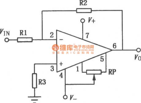
CF1456 series compensated operational amplifier is internal compensated op amp with high gain. Its input current is small, low power consumption, peripherals, zero side with short circuit protection and input over voltage protection. It can be used in summing amplifier, integrator. The similar or directly substitution models are CFl556MT, CF1456CT, CF1556MD, CF1456CD, CF1556MJ, CF1456CJ, CF1456CP and so on. The typical application circuit is shown as above. (View)
View full Circuit Diagram | Comments | Reading(927)
Logic control integrated regulated power supply circuit diagram
Published:2011/5/10 21:41:00 Author:Rebekka | Keyword: Logic control , integrated regulated power supply
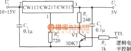
Logic control integrated regulated power supply circuit composed of CW117, CW217 and CW317.
The figure shows the integrated regulated power supply that uses TTL logic level control. When the TTL logic level is high, the transistor VT is saturated. Connect the the resistor R2 to ground, the output voltage is 1.25V. When the logic level is low, the transistor VT will be cut off, the output voltage: Uo = 1.25 (1 + R2/R1) = 5V, the power supply can be used as the logic generator of controlled TTL integrated circuit. (View)
View full Circuit Diagram | Comments | Reading(717)
BA6395AFP BTL-the integrated circuit of 5-channel drive
Published:2011/5/12 20:18:00 Author:Borg | Keyword: integrated circuit, 5-channel
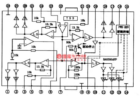
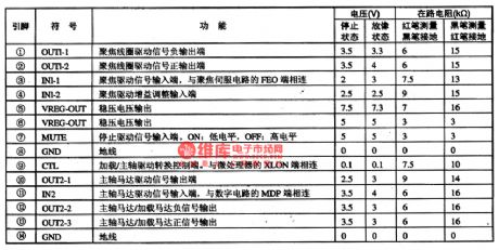
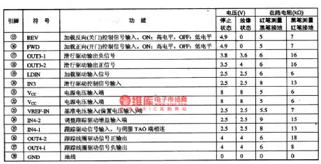
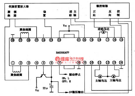
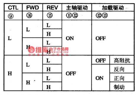
BA6395AFP is an integrated circuit of 5-channel drive produced by Rom Corp., which is used in CD and VCD players of many countries to drive focus coil, tracking coil, spindle motor, axis motor and slide motor, etc.
1.the internal circuit and pin functions of BA6395AFPBA6395AFP chips contains five drive circuits of 5-channel BTL, whose power is large. The internal circuit of the chips is shown in Figure 1. When the temperature is over 175℃, the output current will be impeded.
(View)
View full Circuit Diagram | Comments | Reading(1062)
Storage Battery Voltage Monitor (1)
Published:2011/5/12 3:29:00 Author:Sue | Keyword: Storage, Battery, Voltage, Monitor
Working Principle:
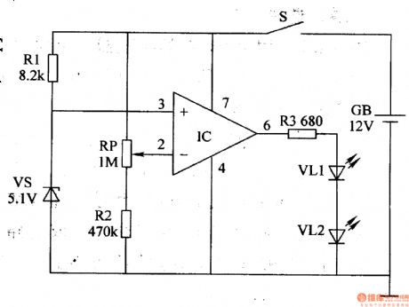
As seen in the figure 7-48, the storage battery voltage monitor circuit consists of operational amplifier integrated circuit IC, resistor R1-R3, potentiometer RP, zener diode VS, power switch S and LED VL1,VL2.
When S is connected, storage battery GB's +12V voltage provides IC's 3 pin with 5.1Vreference voltage after being limited and stablized by R and VS. While another voltage provides IC's 2 pin with sampling voltage after being divided by RP and R2.
When GB's terminal voltage exceeds 10.2V, IC outputshigh level because of 2 pin's voltage is higher than 3 pin's. So VL1 and VL2 are not illuminated.
When GB's terminal voltage doesn't reach 10.2V, IC outputslow level and VL1 VL2 are illuminated, indicating that battery voltage has reduced to preset threshold voltage, which means charging is needed.
Choice of components:
R1-R3: 1/4W metal film or carbon film resistor.
RP:Organic composition solid potentiometer or variable resistor.
VL1,VL2:φ5mm high-brightness red LED.
VS:1/2W,5.1V silicon voltage stablizing diode.
IC:μA741 integrated operational amplifier.
S: Miniture unipolar toggle swtich. (View)
View full Circuit Diagram | Comments | Reading(692)
Storage Battery Voltage Monitor (3)
Published:2011/5/12 4:54:00 Author:Sue | Keyword: Storage Battery, Voltage, Monitor
Working Principle:
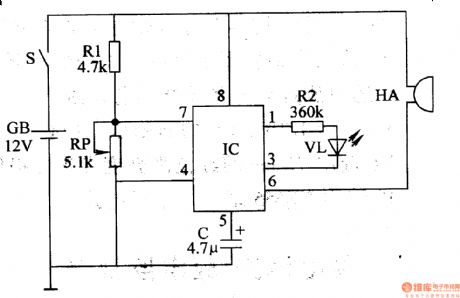
As seen in the figure 7-50, the Storage Battery Monitor Circuit consists of voltage detection warning circuit IC(M5323L), buzzer HA, LED VL and outside resistance-capacitance relating components.
Functions of every pin:1.stablizing voltage output terminal. 2. reference voltage detection terminal. 3. LED VL driving terminal. 4. earth terminal. 5. capacitor oscillate terminal. 6. logic level output terminal. 7. preset voltage output terminal. 8. power terminal
When GB's battery is proper, the voltage of IC's 7 pin is higher than inside reference voltage. Its 6 pin outputs high level and 3 pin outputs no signal.Under this circumstance, LED VL and buzzer HA don't work.
When the voltage is lower than the preset value(11V), IC's 7 pin's voltage is lower than inside reference voltage, which forces the oscillator inside IC begins to work. IC's 3 pin outputs a certain frequency of oscillate pulse signals, making VL keep twinkling. IC's 6 pin outputs low level drive signal, making the buzzer begin to work and make a warning sound. (View)
View full Circuit Diagram | Comments | Reading(1736)
Beijing Wuzhou elevator lighting circuit
Published:2011/5/12 20:05:00 Author:TaoXi | Keyword: Beijing, Wuzhou elevator, lighting circuit
Beijing Wuzhou elevator lighting circuit (View)
View full Circuit Diagram | Comments | Reading(554)
Beijing Wuzhou elevator main circuit
Published:2011/5/12 20:04:00 Author:TaoXi | Keyword: Beijing, Wuzhou, elevator main circuit
Beijing Wuzhou elevator main circuit (View)
View full Circuit Diagram | Comments | Reading(441)
Beijing Chongyun elevator safety loop circuit
Published:2011/5/12 20:03:00 Author:TaoXi | Keyword: Beijing, Chongyun, elevator safety loop
Beijing Chongyun elevator safety loop circuit (View)
View full Circuit Diagram | Comments | Reading(517)
Beijing Chongyun elevator main circuit (2)
Published:2011/5/12 20:00:00 Author:TaoXi | Keyword: Beijing, Chongyun, elevator main circuit
Beijing Chongyun elevator main circuit (2) (View)
View full Circuit Diagram | Comments | Reading(397)
OTIS T0EC-CHVF elevator main circuit
Published:2011/5/12 19:55:00 Author:TaoXi | Keyword: OTIS, elevator, main circuit
OTIS T0EC-CHVF elevator main circuit (View)
View full Circuit Diagram | Comments | Reading(457)
OTIS TOEC-2000VF elevator braker circuit
Published:2011/5/12 19:52:00 Author:TaoXi | Keyword: OTIS, elevator braker
OTIS TOEC-2000VF elevator braker circuit (View)
View full Circuit Diagram | Comments | Reading(445)
OTIS TOEC-2000VF elevator maintenance circuit
Published:2011/5/12 19:50:00 Author:TaoXi | Keyword: OTIS, elevator maintenance circuit
OTIS TOEC-2000VF elevator maintenance circuit (View)
View full Circuit Diagram | Comments | Reading(642)
OTIS TOEC-40 elevator control power supply circuit (1)
Published:2011/5/12 19:39:00 Author:TaoXi | Keyword: OTIS, elevator control, power supply circuit
OTIS TOEC-40 elevator control power supply circuit (1) (View)
View full Circuit Diagram | Comments | Reading(584)
OTIS TOEC-40 elevator control power supply circuit
Published:2011/5/12 19:37:00 Author:TaoXi | Keyword: OTIS, elevator control, power supply circuit
OTIS TOEC-40 elevator control power supply circuit (View)
View full Circuit Diagram | Comments | Reading(608)
OTIS TOEC-40 elevator two parallel outbound button and the indicator light circuit
Published:2011/5/12 19:34:00 Author:TaoXi | Keyword: OTIS, elevator, parallel outbound button, indicator light
OTIS TOEC-40 elevator two parallel outbound button and the indicator light circuit (View)
View full Circuit Diagram | Comments | Reading(451)
OTIS TOEC-40 elevator floor indicator circuit
Published:2011/5/12 19:30:00 Author:TaoXi | Keyword: OTIS, elevator, floor indicator
OTIS TOEC-40 elevator floor indicator circuit (View)
View full Circuit Diagram | Comments | Reading(467)
OTIS TOEC-40 elevator internal choice button and the indicator light circuit
Published:2011/5/12 19:29:00 Author:TaoXi | Keyword: OTIS, elevator, internal choice button, indicator light
OTIS TOEC-40 elevator internal choice button and the indicator light circuit (View)
View full Circuit Diagram | Comments | Reading(525)
OTIS TOEC-60 elevator control circuit
Published:2011/5/12 19:24:00 Author:TaoXi | Keyword: OTIS, elevator control
OTIS TOEC-60 elevator control circuit (View)
View full Circuit Diagram | Comments | Reading(543)
OTIS TOEC-CHVF elevator-slowdown and the door switch circuit
Published:2011/5/12 19:19:00 Author:TaoXi | Keyword: OTIS, elevator-slowdown, door switch
OTIS TOEC-CHVF elevator-slowdown and the door switch circuit (View)
View full Circuit Diagram | Comments | Reading(484)
OTIS TOEC-CHVF elevator maintenance circuit
Published:2011/5/12 19:17:00 Author:TaoXi | Keyword: OTIS, elevator maintenance circuit
OTIS TOEC-CHVF elevator maintenance circuit (View)
View full Circuit Diagram | Comments | Reading(517)
| Pages:1885/2234 At 2018811882188318841885188618871888188918901891189218931894189518961897189818991900Under 20 |
Circuit Categories
power supply circuit
Amplifier Circuit
Basic Circuit
LED and Light Circuit
Sensor Circuit
Signal Processing
Electrical Equipment Circuit
Control Circuit
Remote Control Circuit
A/D-D/A Converter Circuit
Audio Circuit
Measuring and Test Circuit
Communication Circuit
Computer-Related Circuit
555 Circuit
Automotive Circuit
Repairing Circuit