
Circuit Diagram
Index 1888
The instrument indicator and wiper/washer indicator circuit of Volga 3102
Published:2011/5/12 9:49:00 Author:Borg | Keyword: instrument indicator, wiper/washer indicator, Volga
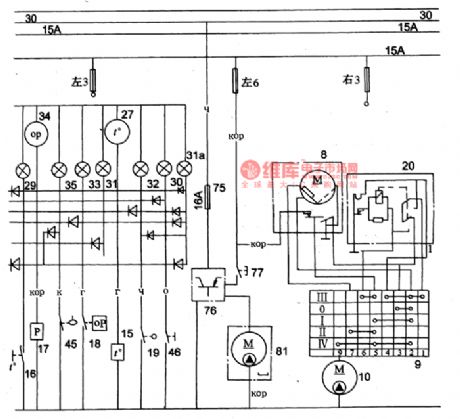
Figure 2 The instrument indicator and wiper/washer indicator circuit of Volga 3102
8-wiper motor; 9-wiper switch;10-washer motor;15-water temperature sensor; 16-engine overheat warning switch; 17-oil sensor; 18-defective oil-pressure alarm switch; 19-brake failure switch;20-wiper interval relay; 27-water thermometer; 29-engine overheat indicator; 30-hand brake indicator; 31-stand-by indicator; 31a-shared alarm lamp; 32-brake failure indicator; 33-low oil pressure warning indicator; 34-oil pressure instrument; 35-short petrol indicator (View)
View full Circuit Diagram | Comments | Reading(1320)
Dynamic display circuit diagram of parallel LED digital tube (common anode)
Published:2011/5/12 2:28:00 Author:Ecco | Keyword: dynamic display, parallel, LED, digital tube
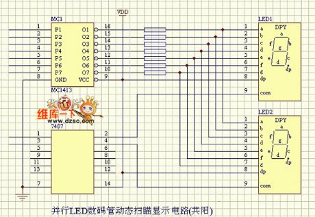
Parallel LED digital tube diaplay circuit diagram is as below:
(View)
View full Circuit Diagram | Comments | Reading(1012)
The circuit diagram of 2.5W+2.5W USB multimedia
Published:2011/5/12 2:28:00 Author:Ecco | Keyword: 2.5W+2.5W , USB multimedia
The circuit diagram of 2.5W+2.5W USB multimedia is as below:
(View)
View full Circuit Diagram | Comments | Reading(633)
BA6664-the intergrated circuit of three-phase spindles driven by motors
Published:2011/5/12 2:04:00 Author:Borg | Keyword: intergrated circuit, three-phase

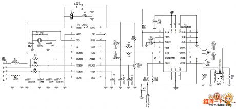
BA6664 is an intergrated circuit of thre-phase spindles that are driven by motors, which is used in DVD player guts of Korean DSC-600A to convert the spindle servo control signals into three-phase driven voltage to drive the three-phase spindle motors.
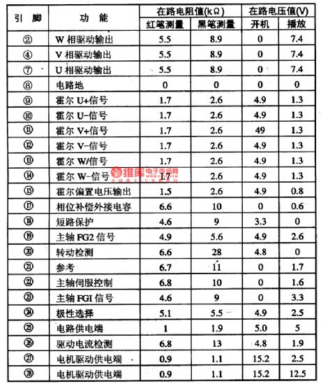
The internal circuit of BA6858AFP chips is listed in Figure 1, and it is in flat 28-pin package with cooling fins. The pin functions and data of it are listed in Table 1 in which the pins of ①,③,⑤,⑥and (16) haven't been listed.
(View)
View full Circuit Diagram | Comments | Reading(666)
BA6844AFP-the intergrated circuit of three-phase spindles driven by motors
Published:2011/5/12 1:55:00 Author:Borg | Keyword: intergrated circuit, three-phase, spindles
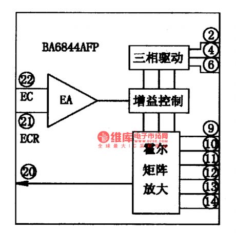
BA6844AFP-the intergrated circuit of three-phase spindles driven by motors
BA6844AFP is an intergrated circuit of thre-phase spindles that are driven by motors, which is used in DVD players to convert the spindle servo control signals into three-phase driven voltage to drive the three-phase spindle motors.
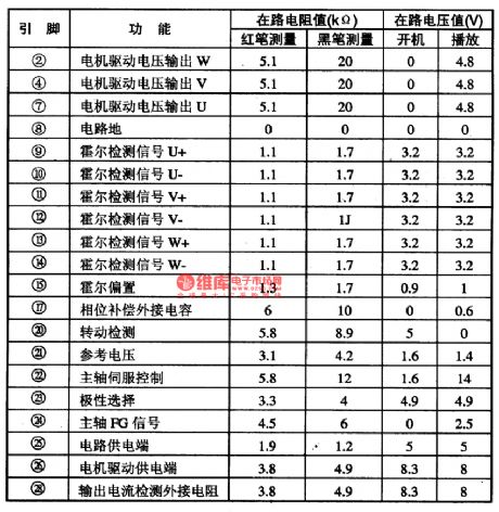
The internal circuit of BA6858AFP chips are listed in Figure 1, and it is in flat 28-pin package with cooling fins. The pin functions and data of it are listed in Table 1 in which ①,③,⑤,⑥,(16),(18) ,(19)and (27) haven't been listed.
(View)
View full Circuit Diagram | Comments | Reading(802)
BA6664-the servo-driven integrated circuit
Published:2011/5/12 2:06:00 Author:Borg | Keyword: intergrated circuit, servo-driven
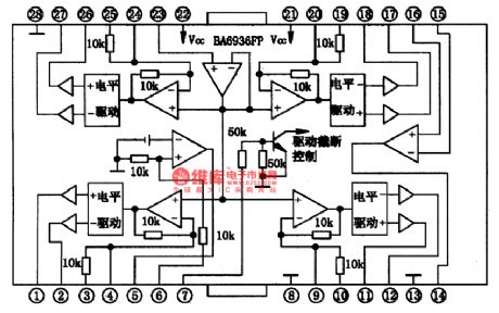
BA6396FP is a servo-driven intergrated circuit produced by Rom Corp., Japan, which is used as servo-drivers in VCD, SVCD and DVD.1.The internal circuitBA6396FP contains sub-circuits of 4-channel BTL, silence and noise control and overheat protection and the internal circuit is shown in Figure 1.
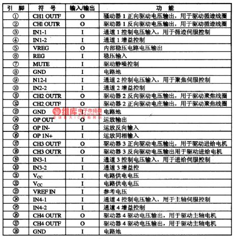
2.pin functionsBA6396FP is in flat 28-pin dual-line package, whose pin functions are listed in Table 1.
(View)
View full Circuit Diagram | Comments | Reading(1150)
Transceiver module composed of the item prevent-lost alarm RCMlA/RCMlB
Published:2011/5/12 1:07:00 Author:TaoXi | Keyword: Transceiver module, item prevent-lost alarm
The transmitter is composed of the RCM1A and the battery, the receiver is composed of the RCM1B receiving module with the double time-delay function, the high voltage generator and the alarm sound circuit.etc. (View)
View full Circuit Diagram | Comments | Reading(913)
Game infrared remote control circuit
Published:2011/5/12 2:43:00 Author:TaoXi | Keyword: Game, remote control circuit
Game infrared remote control circuit (View)
View full Circuit Diagram | Comments | Reading(654)
Transceiver module of the remote control toy car circuit composed of RCMlA/RCMlB
Published:2011/5/12 1:07:00 Author:TaoXi | Keyword: Transceiver module, remote control toy car
Transceiver module of the remote control toy car circuit composed of RCMlA/RCMlB (View)
View full Circuit Diagram | Comments | Reading(714)
Key-buckle type wireless encoding remote controller circuit 1
Published:2011/5/12 1:16:00 Author:TaoXi | Keyword: Key-buckle type, wireless encoding, remote controller
Key-buckle type wireless encoding remote controller circuit 1 (View)
View full Circuit Diagram | Comments | Reading(648)
Key-buckle type wireless encoding remote controller circuit 2
Published:2011/5/12 1:15:00 Author:TaoXi | Keyword: Key-buckle type, wireless encoding, remote controller
Key-buckle type wireless encoding remote controller circuit 2 (View)
View full Circuit Diagram | Comments | Reading(631)
Remote control automatic door circuit
Published:2011/5/12 1:12:00 Author:TaoXi | Keyword: Remote control, automatic door
Transmitter circuit:
Receiving circuit:
Three-phase positive &negative motor which is controlled by this circuit is as shown: (View)
View full Circuit Diagram | Comments | Reading(840)
Single-channel wireless remote control switches TDC1808/TDC1809
Published:2011/5/12 1:37:00 Author:TaoXi | Keyword: Single-channel, wireless remote control switch
The transmitter of the three-way wireless remote control switch is as shown, the receiving circuit is the same to the single channel circuit. (View)
View full Circuit Diagram | Comments | Reading(730)
Infrared remote control music socket circuit 3
Published:2011/5/12 4:22:00 Author:TaoXi | Keyword: Infrared remote control, music socket
The circuit is as shown in the figure. It includes the infrared remote transmitter circuit, the decoder circuit, the relay control circuit and the music circuit.etc. The infrared pulse transmitter circuit is composed of the 25kHz pulse oscillation circuit and the external transmitter driver circuit. And the 25kHz pulse oscillator is composed of the F1, F 2 and R1, R2, C1 components which belong to the Six NAND gate IC CD4069.
Infrared transmitter circuit:
Infrared receiver and control circuit: (View)
View full Circuit Diagram | Comments | Reading(678)
Infrared remote control detector
Published:2011/5/12 3:02:00 Author:TaoXi | Keyword: Infrared, remote control, detector
Infrared remote control detector (View)
View full Circuit Diagram | Comments | Reading(556)
Infrared remote control dimmer switch circuit KA2184A
Published:2011/5/12 3:51:00 Author:TaoXi | Keyword: Infrared, remote control, dimmer switch
The circuit is as shown in the figure. It includes the infrared emission circuit, the infrared receiver circuit, the decoder circuit, the dimming control circuit and the birds voice circuit.etc. You can use this circuit to achieve the remote control switching and dimming of the wall lamp, droplight, the remote control distance is more than 7m, and it is easy to operate and has reliable performance.
Infrared emission circuit:
Oscillation frequency:
Infrared receiving control circuit: (View)
View full Circuit Diagram | Comments | Reading(730)
Infrared remote control music socket circuit 1
Published:2011/5/12 4:02:00 Author:TaoXi | Keyword: Infrared remote control, music socket
The infrared remote control music socket circuit is as shown, it is composed of the pulse oscillator circuit , the buffer stage and the driver stage.
Infrared receiving controller:
(View)
View full Circuit Diagram | Comments | Reading(650)
BA6297AFP-the servo-driven intergrated circuit
Published:2011/5/12 2:56:00 Author:Borg | Keyword: servo-driven, intergrated circuit
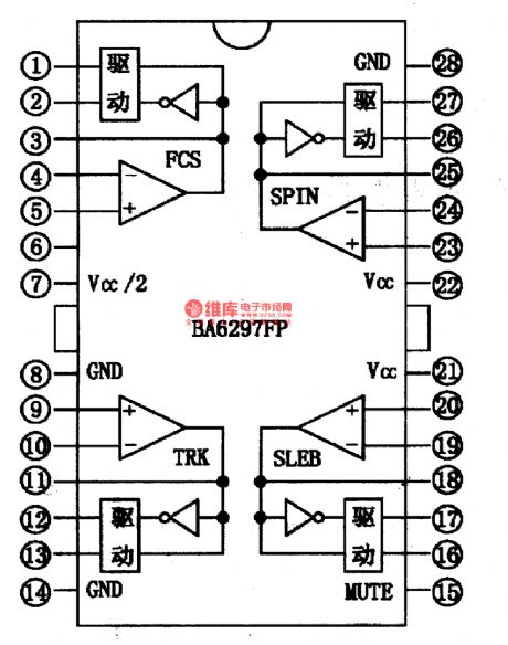
BA6297AFP-the servo-driven intergrated circuit
BA6297AP is a servo-driven intergrated circuit produced by Toyo Corp.,Japan, which is used in VCD, SVCD, CVD and DVD players as servo-drivers.
1.the internal circuit
BA6297AP contains 4-channel BTL drive circuits, which can receive PWM controlled signals output by the digital servo IC directly, and then drives the executing components of drive laser heads after filtering and magnifying those signals.
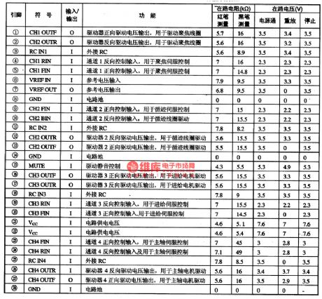
2.pin functions and data
BA6297AP is in 28-pin dual in-line package with cooling fins, whose data are from Changhong VD-900O VCD players.
(View)
View full Circuit Diagram | Comments | Reading(898)
New phone line protection circuit diagram
Published:2011/5/8 5:47:00 Author:Rebekka | Keyword: New phone line protection
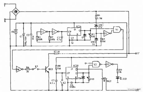
New phone line protection circuit is shown as below. Telephone wiring in the T and R ends. When someone steal the outside line. BG1 will be conducted. The voltage between T and R is only 2V. The protection will reset automatically after hanging up. When you are calling, press K. If the LED does not light means there is eavesdropping; If the LED lights, it shows that lines are not tapped. (View)
View full Circuit Diagram | Comments | Reading(1483)
The predetermined analog timer circuit diagram
Published:2011/5/8 7:36:00 Author:Rebekka | Keyword: analog timer
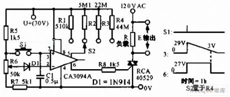
The predetermined analog timer circuit diagram is shown as below. It uses programmable power switch CA3094 to constitute the predetermined analog timer. The circuit gives four kinds of delay selection. It uses potentiometer R6 to set the initial time. When S2 connects to R4, click S1, the triac can work for 1 hour. (View)
View full Circuit Diagram | Comments | Reading(1109)
| Pages:1888/2234 At 2018811882188318841885188618871888188918901891189218931894189518961897189818991900Under 20 |
Circuit Categories
power supply circuit
Amplifier Circuit
Basic Circuit
LED and Light Circuit
Sensor Circuit
Signal Processing
Electrical Equipment Circuit
Control Circuit
Remote Control Circuit
A/D-D/A Converter Circuit
Audio Circuit
Measuring and Test Circuit
Communication Circuit
Computer-Related Circuit
555 Circuit
Automotive Circuit
Repairing Circuit