
Circuit Diagram
Index 1882
CC4527-BCD series multiplier integrated circuit diagram
Published:2011/5/11 3:33:00 Author:Fiona | Keyword: multiplier integrated
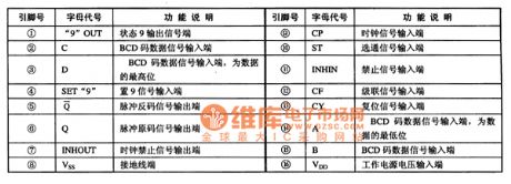
CC4527 is a BCD series multiplier integrated circuit and a universal digital device.It's widely used in various digital signal processing circuit, such as digital instrumentation, communications systems etc.1. The pin functions
CC4527 integrated circuits use 6-pin dual in-line package.The pin functions are listed in Table 1.
Table 1 CC4527 integrated circuits' pin functions
2. Typical application circuit
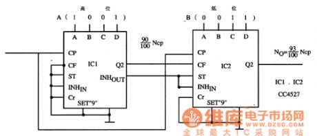
Evenly spaced type of frequency ratio control circuit posed by the CC4527 integrated circuits is shown in Figure 1.
Figure 1 Evenly spaced frequency ratio control circuit posed by the CC4527 integrated circuits (View)
View full Circuit Diagram | Comments | Reading(739)
Electronic stethoscope(1)
Published:2011/5/10 20:38:00 Author:Nicole | Keyword: electronic stethoscope
The traditional medical stethoscope has no amplification, weak voice, it's uncomfortable when wedge it in ears, it is affected by environmental noise easily. This electronic stethoscope adopts multi-stage low noise amplifier, the output volume is adjustable, the frequency respondse has good effect, the background noise is low, it also LED display function.
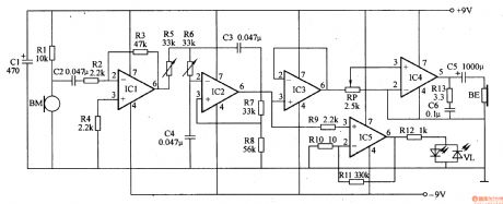
This electronic stethoscope circuit is composed of pickup sensor, preamplifier, low-pass filter amplifier, buffer, audio amplifier, LED display circuit, it is shown in the figure 9-136.
The pickup sensor circuit is composed of microphone BM and R1.
The preamplifier is composed of integrated operational amplifier circuit and resistors R2-R5.
The low-pass filter amplifier is composed of operational amplifier integrated circuit IC2 and transistors R6-R8, capacitors C3, C4, the cut-off frequency is slightly larger than 100Hz.
The buffer amplifier is composed of integrated operational amplifier circuit IC3.
The audio amplifier consists of volume potentiometer RP, low voltage audio amplifier integrated circuit IC4, resistor R13, capacitors C5, C6.
(View)
View full Circuit Diagram | Comments | Reading(6308)
Direct reading type hygrometer circuit
Published:2011/5/11 0:01:00 Author:Fiona | Keyword: Direct reading type, hygrometer
Illustration is direct reading type hygrometer circuit, including RH for chlorinated hammer humidity sensitive resistor. The power supply's humidity measurement bridge is made up by VT1, VT2 and T1 etc and the power supply's oscillation frequency is 250-1000Hz.Bridge output signal through the transformer T2, C3 coupled to the VT3, and the signal amplified by VT3 enters microammeter after it is bridge rectifiered by VD1-VD4, indicates the relative humidity changeslead to the current changes. By calibrating and Characterizing the humidity on the microampere dial ,it becomea simple and practical direct reading hygrometer.
var translatedXML = null;
(View)
View full Circuit Diagram | Comments | Reading(591)
CCU-FDTV-06 single chip microcomputer integrated circuit diagram
Published:2011/5/11 3:31:00 Author:Fiona | Keyword: single chip microcomputer
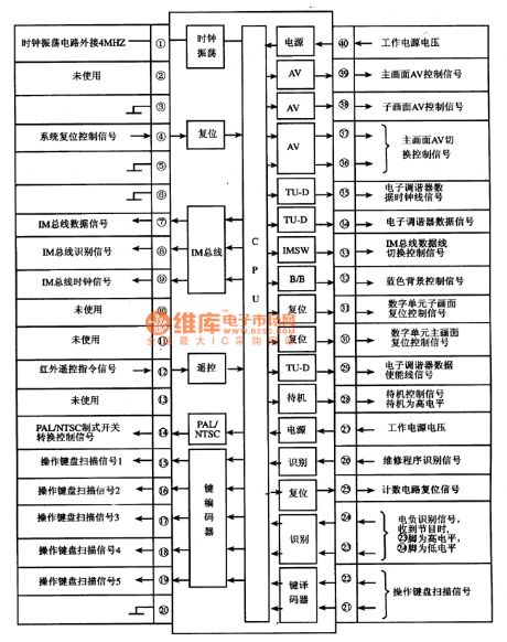
CCUFDTV06 is a single chip microcomputer integrated circuits.Iti (View)
View full Circuit Diagram | Comments | Reading(765)
Electronic thermometer(2)
Published:2011/5/10 21:53:00 Author:Nicole | Keyword: electronic thermometer
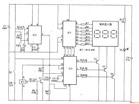
The temperature measuring range of this electronic thermometer is 0-50℃, the precision is 0.1℃, the measurement results are intuitively displayed by digital display.
The working principle of this circuit
This electronic thermometer circuit is composed of temperature detection circuit, monostable circuit, digital display drive circuit and power supply circuit, it is shown in the figure 9-133.
The temperature detection circuit is made of temperature sensor integrated circuit IC1, resistors R3-R5 and transistor V1.
The monostable circuit is composed of resistors R1, R2, capacitors C2, C3 and time base integrated circuit IC2.
The digital display drive circuit consists of digital display, counter integrated circuit IC3, decoding drive integrated circuit IC4, resistors R7-R16 and transistors V2-V4.
The power supply circut is composed of power supply switch S2, battery GB, filter capacitors C1, C6, current limiting resistor R17 and power supply indicator LED VL.
When the power supply switch S2 is turned on, one way of GB's 12V DC voltage is fed to IC2-IC4 by Cl、C6 filter, the other way is current limited and reduced voltage by R17 then to light up VL.
(View)
View full Circuit Diagram | Comments | Reading(6901)
CAT2404P memory integrated circuit diagram
Published:2011/5/11 3:34:00 Author:Fiona | Keyword: memory
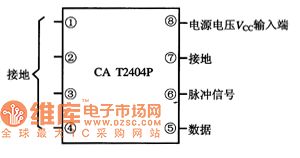
CAT2404P is a piece of memory memory integrated circuits.It's widely used in color TV, air conditioning control circuits, audio systems, DVD players control system.
1. Features
CAT2404P integrated circuits' in-circuit is mainly composed by the internal circuitry memory matrix, the data input / output interface circuit, the clock pulse processing circuits, test circuits, and other auxiliary functions circuit etc.
2. pin functions and data
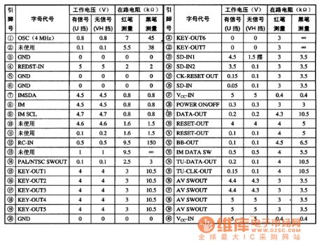
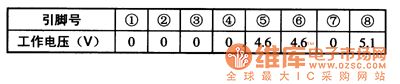
CAT2404P integrated circuits use 8-pin dual in-line package, the pin functions are shown in Figure 1, the typical operating voltage are listed in Table 1.
Figure 1 CAT2404P integrated circuits' pin functions
Table 1 The typical operating voltage of CAT2404P integrated circuits
(View)
View full Circuit Diagram | Comments | Reading(560)
Electronic thermometer(1)
Published:2011/5/10 21:31:00 Author:Nicole | Keyword: electronic thermometer
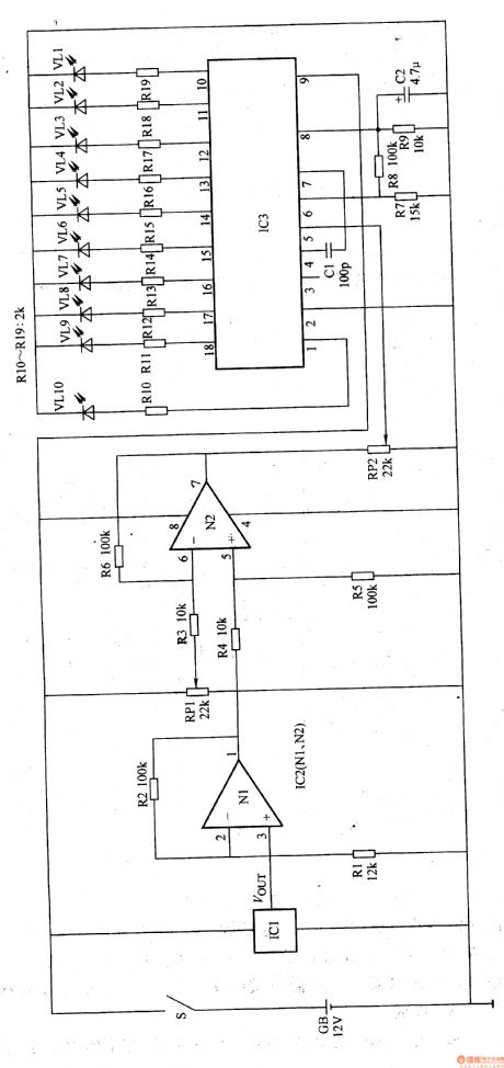
This electronic thermometer adopts temperature sensor to detect temperature, the measured temperature is displayed by LED. The temperature measuring range is 35-40T, the temperature resolution is 0.5℃(it can display 10 temperature values such as 35.5℃、36℃、36.5C…39℃、39.5℃、40℃).
The working principle of this circuit
This electronic thermometer circuit is composed of temperature measurement amplifier circuit, comparison amplifier circuit and temperature indication circuit, it is shown in the figure 9-132.
The temperature measurement amplifier circuit is made of temperature sensor IC1, operational amplifier IC2(Nl、N2) internal N1 and resistors R1, R2.
The comparison amplifier circuit is composed of resistors R3-R6, potentiometers RPl、RP2 and IC2 internal operational amplifier N2.
The temperature indication circuit consists of LED display drive IC3, resistors R7-R19, LED VLl-VLlO and capacitors C1, C2.
If the measured people's temperature is 36℃, VLl and VL2 turn on, and VL3-VLlO off; if the temperature is 37℃, then VLl-VL4 turn on, VL5-VLlO off; if the temperature is 38℃, then VLl-VL6 turn on, VL7-VLlO off, and so on.
(View)
View full Circuit Diagram | Comments | Reading(1328)
formed by common components 4 input 12-bit A-D converter diagram
Published:2011/5/11 3:23:00 Author:Fiona | Keyword: formed by common components, 4 input
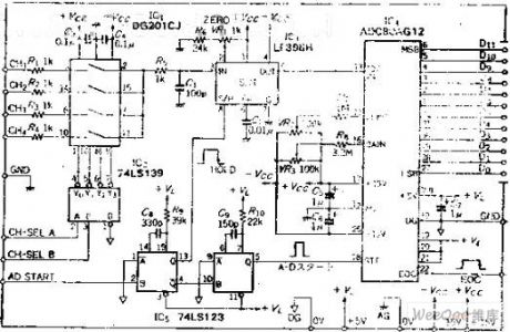
Circuit function
Recently, there is a variety of general-purpose AD conversion expansion board as a personal computer expanded with being sold on the market , if limited specific use, production costs can be low.
This circuit is a 12-bit AD converterusing in sample and hold circuits which is composed of the universal element and 4 inputs. It can enter positive and negative analog signals.
Circuit work
Analog input mux using the standard analog switch DG201, chooses 1~4 channel with decoder IC , channel selection input control by the two positive logic. After selecting channel, input about 10US wide sampling pulse to the sample and hold circuit to keep the analog voltage.The pulse starts to pulse by the AD pulse, using the pulse rising edge to begin 12-bit conversion. The conversion time is about 25US, 12-bit data output from D0 ~ D11. About EOC signal: when A-D conversion starts, EOC is H level and count the clock pulse.After conversion, EOC is back L level, so we can use the method of detecting EOC signai's rising and falling to read the slide 12-bit data.
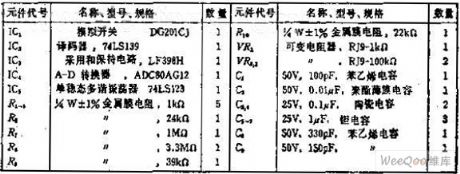
Component selection
(View)
View full Circuit Diagram | Comments | Reading(827)
Frost Alarm Circuit (2)
Published:2011/5/12 2:19:00 Author:Robert | Keyword: Frost, Alarm
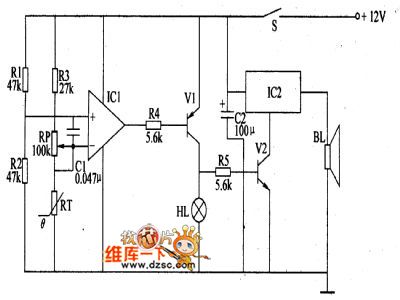
The forst alarm circuit introduced in this example can give the sound and light signal immediately when the frost coming to remind the workers to prepare for anti-frost in time. This device can be widely used in the areas such as agriculture and mining and so on.The circuit's working principle is shown below.This frost alarm circuit is made up by the frost detecting circuit and sound-lignt alarm circuit which is shown in the picture below. The frost detecting circuit is made up by the thermistor RT, resistance R1~R3, potentiometer RP, capacitor C and operational amplifier integrated circuit IC1.The sound-light alarm circuit is made up by resistance R4, R5, transistor V1, V2, alarm alarm indicator lamp HL, sound effect integrated circuit IC2 and speaker BL.When there is no frost, the atmospheric temperature is relatively higher. RT is in low-resistance mode, IC in-phase input port's voltage is higher than the out-phase input port's, and it outputs high voltage level to make V1 and V2 disconnected. So HL does not light and IC2 does not work, BL has no sound.In case of the frost coming, the atmospheric temperature is low and the RT's resistance would rise to make the IC's out-phase input port voltage higer than the in-phase input port's voltage and make its output port's voltage be low voltage level. So V1 and V2 is connected and HL would light, IC2 is electrified to work and BL would have the alarm sound.
(View)
View full Circuit Diagram | Comments | Reading(936)
Mine-used electric coal drill safely using electricity controller
Published:2011/5/11 3:59:00 Author:Nicole | Keyword: electric coal drill, safely using electricity, controller
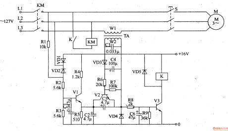
This mine-used electric coal drill safely using electricity controller can use electric drill handle switch to conveniently achieve long distance automatic power failure and power transmission, it greatly reduces the cable charging time and increases the security of using electricity.
The working principle of this circuit
This mine-used electric coal drill safely using electricity controller circuit is composed of trigger control circuit, hold circuit and control implement circuit, it is shown in the figure 8-33.
The trigger control circuit is made of electric drill handle switch S, resistors R1-R5, diodes VD1, VD2, capacitors C1, C2 and transistor V1.
The hold circuit is composed of current transformer TA, capacitors C3-C5, diodes VD3, VD4, resistors R6, R7 and transistor V2.
The control implement circuit consists of resistors R8, R9, capacitor C6, transistor V3, diode VD5, relay K and AC contactor KM.
When S is turned off, the current of L3 phase line disappears, then V2 cuts off, V3 cuts off too, K and KM gives off, M stops turning due to power failure.
(View)
View full Circuit Diagram | Comments | Reading(2587)
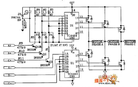
Three phase brushless motor drive circuit diagram
Published:2011/5/12 21:33:00 Author:Nicole | Keyword: Three phase, brushless motor drive
View full Circuit Diagram | Comments | Reading(4097)
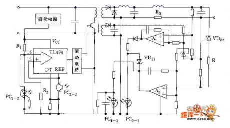
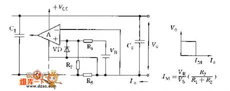
Combination protection circuit of constant current current-limiting circuit and disconnection current protection circuit
Published:2011/5/12 21:28:00 Author:Nicole | Keyword: Combination protection, constant current, current-limiting, disconnection, current protection
View full Circuit Diagram | Comments | Reading(678)
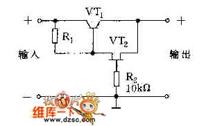
Protection circuit diagram adopted field effect transistor
Published:2011/5/12 21:34:00 Author:Nicole | Keyword: field effect transistor, protection
View full Circuit Diagram | Comments | Reading(498)
Typical constant current overcurrent protection circuit diagram
Published:2011/5/12 21:31:00 Author:Nicole | Keyword: constant current, overcurrent protection
View full Circuit Diagram | Comments | Reading(807)
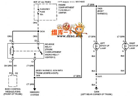
Cadillac deville reverse class circuit diagram
Published:2011/5/12 21:22:00 Author:Nicole | Keyword: Cadillac deville, reverse class
View full Circuit Diagram | Comments | Reading(497)
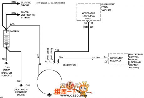
Cadillac deville charging system circuit diagram
Published:2011/5/12 21:17:00 Author:Nicole | Keyword: Cadillac deville, charging system
View full Circuit Diagram | Comments | Reading(2853)
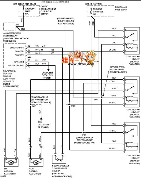
Cadillac deville cooling fan circuit diagram
Published:2011/5/12 21:16:00 Author:Nicole | Keyword: Cadillac deville, cooling fan
View full Circuit Diagram | Comments | Reading(821)
China vehicle engine circuit diagram
Published:2011/5/8 6:29:00 Author:Rebekka | Keyword: China vehicle engine circuit
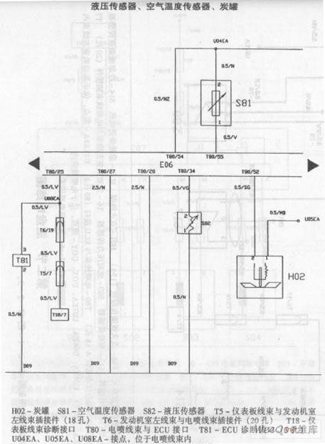
China vehicle engine circuit diagram. (View)
View full Circuit Diagram | Comments | Reading(537)
The circuit diagram of message controller using voice to replace telephone ring
Published:2011/5/8 6:01:00 Author:Rebekka | Keyword: message controller
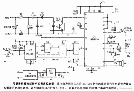
It is a message controller that uses voice to instead of telephone ring. The circuit is a diargam of message controlle. It uses voice chip ISD1016 to replace telephone ring. The controller can store message, music, a song or some other voice to replace monotonous ring. (View)
View full Circuit Diagram | Comments | Reading(1682)
Chinese car wipers spray washing device circuit diagram
Published:2011/5/8 6:09:00 Author:Rebekka | Keyword: Chinese car wipers spray washing device
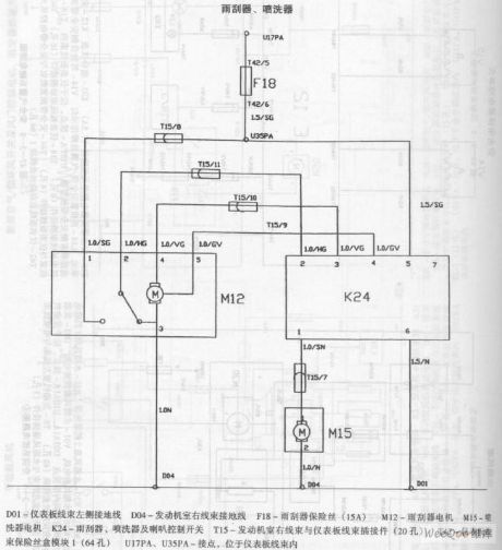
Chinese car wipers spray washing device circuit diagram. (View)
View full Circuit Diagram | Comments | Reading(575)
| Pages:1882/2234 At 2018811882188318841885188618871888188918901891189218931894189518961897189818991900Under 20 |
Circuit Categories
power supply circuit
Amplifier Circuit
Basic Circuit
LED and Light Circuit
Sensor Circuit
Signal Processing
Electrical Equipment Circuit
Control Circuit
Remote Control Circuit
A/D-D/A Converter Circuit
Audio Circuit
Measuring and Test Circuit
Communication Circuit
Computer-Related Circuit
555 Circuit
Automotive Circuit
Repairing Circuit