
Circuit Diagram
Index 1880
Toy tank wireless remote control circuit HS101/HS201
Published:2011/5/11 20:33:00 Author:TaoXi | Keyword: Toy tank, wireless remote control
The toy tank coding emitter:
The toy tank receiving decode circuit: (View)
View full Circuit Diagram | Comments | Reading(859)
mini wireless call systems BA1401/TDA7010T
Published:2011/5/11 20:49:00 Author:TaoXi | Keyword: mini, wireless call system
Transmitter (View)
View full Circuit Diagram | Comments | Reading(736)
High confidentiality electronic lock circuits T630 and T631
Published:2011/5/12 7:05:00 Author:TaoXi | Keyword: High confidentiality, electronic lock
You can use the jump yard decoding circuit to form the high confidentiality electronic lock that can be used in the safety deposit box, the confidential file cabinet, the confidential room applications to ensure their safety. The high confidentiality electronic lock circuit which is composed of the jump yards decoding circuit (ACM1330E/ACM1550D) and the long-wave remote control transmitter / receiver circuit (T630/T631) is as shown in the figure. (a) is the coded excitation circuit; (b) is the receiving decoder circuit. (View)
View full Circuit Diagram | Comments | Reading(511)
Multichannel wireless remote control circuits F36-F and F36-J
Published:2011/5/12 7:24:00 Author:TaoXi | Keyword: Multichannel, wireless remote control
This circuit uses the multichannel wireless remote control circuit which is composed of the F36-F and F36-J. In the transmission circuit, we use the DTMF coding & decoding circuit to change the launch button input signal into the 4-bit binary code and then input this signal to the F36-F to send out. In the receiving circuit, the F36-J receives the remote control signal and changes this signal into the 4-bit binary code, then changes this 4-bit binary code into the channel control signal through a four-sixteen line decoder to control the corresponding circuit.
Theremote controltransmission circuit:
The receiver decoding circuit: (View)
View full Circuit Diagram | Comments | Reading(714)
Children lost warning devices NE555 and TDA7000
Published:2011/5/12 7:32:00 Author:TaoXi | Keyword: Children lost, warning device
The FM transmitter circuit has two parts: the low frequency modulation oscillator and the carrier frequency oscillator transmitter circuit, as the figure (a) shown.
The receiving circuit is as shown in figure (b). (View)
View full Circuit Diagram | Comments | Reading(620)
DTMF coding sixteen-channel remote control circuit
Published:2011/5/12 7:35:00 Author:TaoXi | Keyword: DTMF, coding, sixteen-channel, remote control
Transmitter circuit:
Receiving circuit: (View)
View full Circuit Diagram | Comments | Reading(734)
DTMF seven-channel remote controllers MK5087 and TDA7010
Published:2011/5/12 7:41:00 Author:TaoXi | Keyword: DTMF, seven-channel, remote controller
The transmitter circuit which is composed of the DTMF encoder MK5087 and the coding keyboard:
The receiving circuit: (View)
View full Circuit Diagram | Comments | Reading(809)
TV remote controller 20
Published:2011/5/12 8:20:00 Author:TaoXi | Keyword: TV, remote controller
TV remote controller 20 (View)
View full Circuit Diagram | Comments | Reading(671)
TV remote controller 21
Published:2011/5/12 8:20:00 Author:TaoXi | Keyword: TV, remote controller
TV remote controller 21 (View)
View full Circuit Diagram | Comments | Reading(671)
TV remote controller 19
Published:2011/5/12 8:20:00 Author:TaoXi | Keyword: TV, remote controller
TV remote controller 19 (View)
View full Circuit Diagram | Comments | Reading(642)
Detection and alarm circuit composed of the TWH9248 and TWH9249
Published:2011/5/12 8:14:00 Author:TaoXi | Keyword: Detection, alarm
The key components datathat will be used in this article: TWH9248 TWH9249
The TWH9248/TWH9249 is a pair of microwave sensing components (also known as the radar detector), and they can be used in the movement detection of the human body or object, the effective detection range is 3-6m, the operating voltage is 9-12V.
(View)
View full Circuit Diagram | Comments | Reading(604)
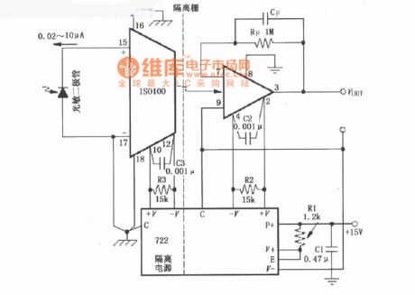
Dual-Channel isolation unipolar photodiode amplifier circuit diagram composed of ISO100
Published:2011/5/12 22:08:00 Author:Ecco | Keyword: Dual-Channel, isolation , unipolar , photodiode , amplifier
View full Circuit Diagram | Comments | Reading(867)
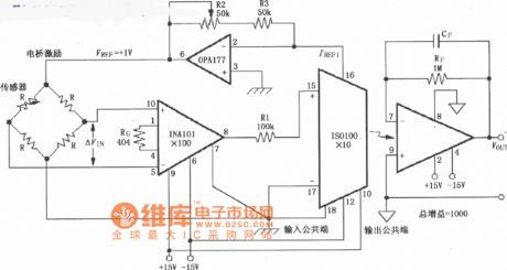
Unipolar precision bridge isolation amplifier circuit diagram composed of ISO100
Published:2011/5/12 22:06:00 Author:Ecco | Keyword: Unipolar, precision , bridge , isolation, amplifier
View full Circuit Diagram | Comments | Reading(744)
Sony KV-25G protection circuit
Published:2011/5/12 20:27:00 Author:TaoXi | Keyword: Sony, protection circuit
Sony KV-25G protection circuit (View)
View full Circuit Diagram | Comments | Reading(459)
Low cost temperature controller circuit
Published:2011/5/12 20:40:00 Author:TaoXi | Keyword: Low cost, temperature controller
Low cost temperature controller circuit (View)
View full Circuit Diagram | Comments | Reading(542)
High-power temperature control circuit with the MPM module
Published:2011/5/12 20:41:00 Author:TaoXi | Keyword: High-power, temperature control, MPM module
High-power temperature control circuit with the MPM module (View)
View full Circuit Diagram | Comments | Reading(704)
Temperature control interface circuit with the KTYlo silicon temperature sensor
Published:2011/5/12 20:43:00 Author:TaoXi | Keyword: Temperature control, interface circuit, silicon temperature sensor
Temperature control interface circuit with the KTYlo silicon temperature sensor (View)
View full Circuit Diagram | Comments | Reading(704)
Temperature change indicator circuit with the voice instructing
Published:2011/5/12 20:43:00 Author:TaoXi | Keyword: Temperature change indicator, voice instructing
Temperature change indicator circuit with the voice instructing (View)
View full Circuit Diagram | Comments | Reading(745)
Greenhouse temperature and humidity automatic controller circuit
Published:2011/5/12 20:50:00 Author:TaoXi | Keyword: Greenhouse, temperature, humidity, automatic controller
Greenhouse temperature and humidity automatic controller circuit (View)
View full Circuit Diagram | Comments | Reading(697)
BA628N-the dual-control integrated circuit of motor drive
Published:2011/5/12 21:59:00 Author:Borg
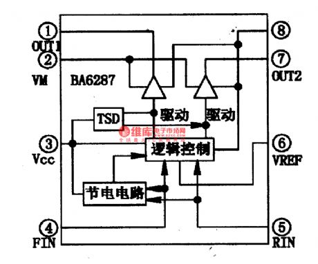
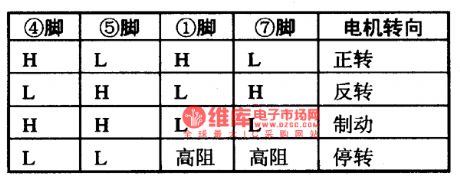
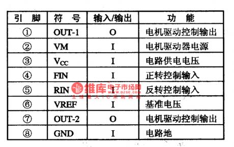
BA628 is a-dual control integrated circuit of motor drive produced by Toyo Corp., which is widely used in CD and VCD players as motor drives.1.the internal circuit BA6287N contains logic control circuit and drive circuit, whose internal circuit is as shown in Figure 1.
2.pin functionsBA6287N is in 8-lead dual flat package, whose pin functions are listed in Table 1.
Notes: the logical relationship of BA6287N is listed in Table 1, by which we can judge if IC is malfunctioning (View)
View full Circuit Diagram | Comments | Reading(655)
| Pages:1880/2234 At 2018611862186318641865186618671868186918701871187218731874187518761877187818791880Under 20 |
Circuit Categories
power supply circuit
Amplifier Circuit
Basic Circuit
LED and Light Circuit
Sensor Circuit
Signal Processing
Electrical Equipment Circuit
Control Circuit
Remote Control Circuit
A/D-D/A Converter Circuit
Audio Circuit
Measuring and Test Circuit
Communication Circuit
Computer-Related Circuit
555 Circuit
Automotive Circuit
Repairing Circuit