
Circuit Diagram
Index 1877
inverting amplifier with high input impedance circuit
Published:2011/5/15 2:38:00 Author:John | Keyword: inverting amplifier
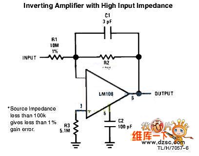
Inverting amplifier with high input impedance circuit is shown below.
(View)
View full Circuit Diagram | Comments | Reading(2139)
E-fuse circuit
Published:2011/5/15 2:35:00 Author:John | Keyword: E-fuse
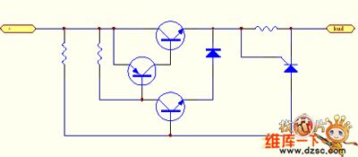
E-fuse circuit is shown below.
(View)
View full Circuit Diagram | Comments | Reading(638)
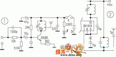
Microphone circuit (wireless)
Published:2011/5/15 2:56:00 Author:John
Microphone circuit (wireless) is given in the following.
(View)
View full Circuit Diagram | Comments | Reading(950)
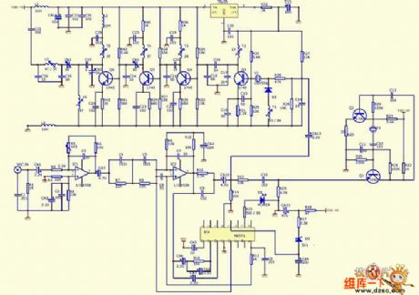
UC3842 Application circuit
Published:2011/5/15 2:51:00 Author:John
UC3842 Application circuit is shown above.
(View)
View full Circuit Diagram | Comments | Reading(16417)
Audio amplifier circuit
Published:2011/5/15 2:42:00 Author:John | Keyword: Audio amplifier
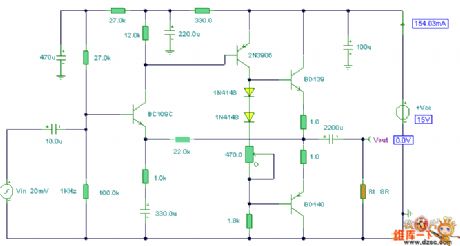
Audio amplifier circuit is shown below.
(View)
View full Circuit Diagram | Comments | Reading(858)
Other detection circuits of Santana 20OOGLi
Published:2011/5/15 0:40:00 Author:Borg | Keyword: detection circuits, Santana

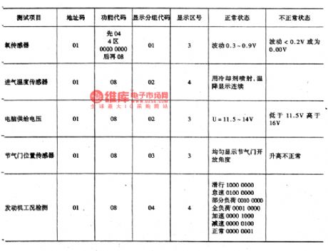
With V.A.G151 fault diagnosis equipment, we can not only find out the fault position,but also detect the working parameters of relevant parts, which can provide dependable back-up for exactly judging faults. Apart from the above detectors, there are also throttle sensors. Furthermore, the coolant temperature sensors, admission temperature and computer power voltage can be detected with V.A.G diagnosis meter. The measuring methods are almost the same, just remember the address code of 01, and input the relevant function codes, then detection is to start.
(View)
View full Circuit Diagram | Comments | Reading(471)
Reset circuit
Published:2011/5/15 2:40:00 Author:John
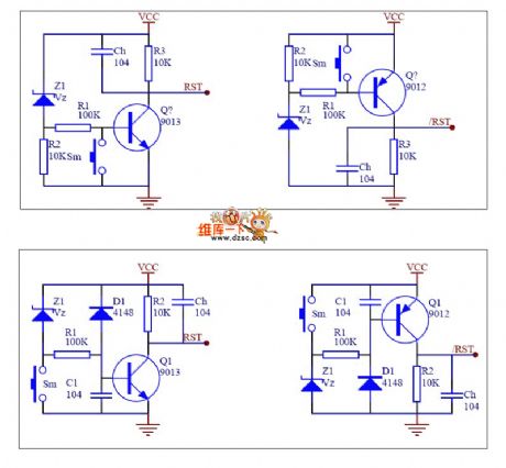
Reset circuit is shown below.
(View)
View full Circuit Diagram | Comments | Reading(989)
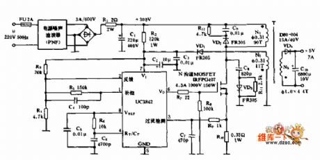
A3 switch power supply circuit
Published:2011/5/15 2:54:00 Author:John | Keyword: A3 switch
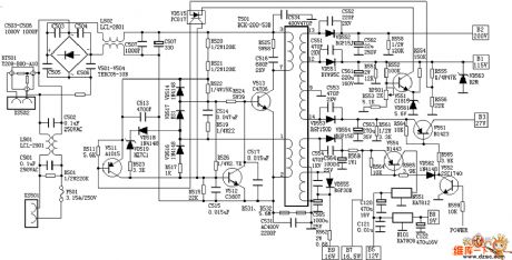
A3 switch power supply circuit is shown below.
(View)
View full Circuit Diagram | Comments | Reading(768)
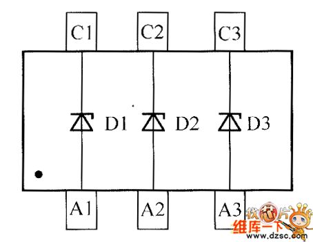
Internal circuit of diode DDZX5V2BTS
Published:2011/5/15 2:47:00 Author:John | Keyword: diode DDZX5V2BTS

Internal circuit of diode DDZX5V2BTS is shown below.
(View)
View full Circuit Diagram | Comments | Reading(460)
making circuit for wireless headphones
Published:2011/5/15 3:12:00 Author:John | Keyword: wireless headphone
Making circuit for wireless headphones is shown in the following.
(View)
View full Circuit Diagram | Comments | Reading(1657)
Internal circuit of crystal diode DDZX9690TS
Published:2011/5/15 3:10:00 Author:John | Keyword: crystal diode DDZX9690TS
Internal circuit of crystal diode DDZX9690TS is given in the following.
(View)
View full Circuit Diagram | Comments | Reading(560)
Frost Alarm (2)
Published:2011/5/14 4:13:00 Author:Sue | Keyword: Frost, Alarm
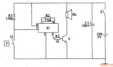
Working Principle:
As seen in the figure 4-110, the frost alarm circuit consists of power circuit, temperature detection controlled circuit and alarm circuit.
When S is connected, the alarm circuit prepares to work. When the temperature is higher than 1℃, Q is disconnected and the alarm circuit doesn't work, and BL makes no sound. When the temperature is lower than1℃, Q is connected and IC begins to work. IC's 3 pin will output audio electric signal, which will promote BL to make a warning sound after the signal is amplified by V. (View)
View full Circuit Diagram | Comments | Reading(831)
Clock coupling circuit diagram(can be efficiently transmitted 5KHZ clock pulse)
Published:2011/5/13 3:38:00 Author:Ecco | Keyword: Clock coupling , efficiently , transmitted , 5KHZ , clock pulse
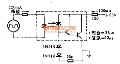
The circuit uses gallium arsenide infrared emitting diode and it is optically coupled to the silicon plane photoelectric mulriple pipe. Circuit requires insulation and it transfers 5KHz the clock pulse in high efficiency according to maximum rated voltage and current. Circuit uses photoelectric mulriple pipe which is led by the base to improve recovery time. The load is 400Ω. clock coupling circuit is shown as the chart (can be efficiently transmitted 5KHZ clock pulse).
(View)
View full Circuit Diagram | Comments | Reading(525)
Amproluck W850ES microwave auto-sensing electronic microwave circuit diagram
Published:2011/5/13 3:46:00 Author:Ecco | Keyword: Amproluck, microwave , auto-sensing , electronic microwave
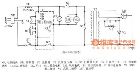
XP-power plug, FU-fuse, ST-temperature control, T1-low-voltage transformers, S1, S2-door interlock switch, S3-threshold control switch, RT-thermal sensor, K1, K2-relay, EL- furnace light, M1-wheel motor, M2-fan motor, T2-high-voltage transformer, C-high voltage capacitor, V1-protection diode, V2-high voltage diode, MT-magnetron
(View)
View full Circuit Diagram | Comments | Reading(3516)
Inverse proportion basic circuit diagram
Published:2011/5/13 3:54:00 Author:Ecco | Keyword: Inverse proportion, basic circuit
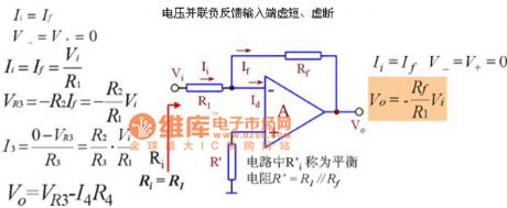
1. The basic circuit: Voltage series negative feedbackThe input end is virtual short, virtual-off The features:
Reverse side is the virtual ground, so the common mode input can be regarded as 0, the CMRR on the op amp requires low. The output resistance is small with a strong load capacity When it requires a large magnification, the feedback resistor is high, the stability is poor. If the required magnification is 100, R1 = 100K, Rf = 10M.
(View)
View full Circuit Diagram | Comments | Reading(759)
5082-4350 Automatic amplitude control circuit diagram with optical isolation
Published:2011/5/13 3:28:00 Author:Ecco | Keyword: Automatic amplitude , control circuit, optical isolation
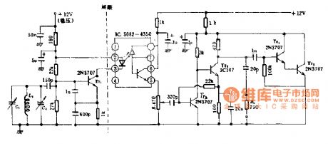
The circuit has a long time frequency stability, temperature changes can be ignored, and it eliminates the pulse load on the frequency, the oscillator uses emitter coupled circuit and 2N3707 low-noise transistor. In addition, it is also given the output amplifier and automatic amplitude control circuit. This circuit is designed for ham using radio equipment.
(View)
View full Circuit Diagram | Comments | Reading(975)
SBC overvoltage protection circuit diagram
Published:2011/5/15 5:14:00 Author:Rebekka | Keyword: SBC overvoltage protection
The circuit is shown as above. It can use +5 V operating voltage SBC power supply. It can prevent the damage of the SBC to +5 V the entire SBC because of overvoltage. (View)
View full Circuit Diagram | Comments | Reading(785)
In-phase proportion circuit diagram
Published:2011/5/13 3:50:00 Author:Ecco | Keyword: In-phase , proportion
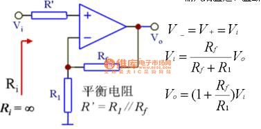
1. The basic circuit: Voltage series negative feedbackThe input end is virtual short, virtual-off The features: input resistance is high, output resistance is small, the load capacity is highV-= V + = Vi, so the common mode input is equal to the input signal, the common mode on the op amp's can suppress the ratio. (View)
View full Circuit Diagram | Comments | Reading(508)
HA11211-The integrated circuit of FM-IF, frequency discrimination with AM-IF and audio magnifying
Published:2011/5/13 2:26:00 Author:Borg | Keyword: FM-IF, frequency discrimination, AM-IF
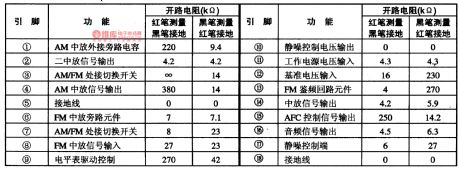
HA11211 a FM- and AM- IF integrated circuit produced by Hitachi Corp., Japan, specially for FM stereos,which is used in stereo systems that have radio FM.1.HA11211 internal circuit and pin functionsHA11211 FM is run by the triple-level balanced crane differential amplification circuit, which is characterized with high sensitivity, high wave-detection voltage, low distortion and high noise-signal ratio, and the discrimination output is delivered to the outside stereo conditioning circuit till it has been magnified by the internal low-noise broadband audio.
(View)
View full Circuit Diagram | Comments | Reading(1015)
BA5208AF-the integrated 2-channle amplifier circuit of recording/reproduceing
Published:2011/5/13 3:41:00 Author:Borg | Keyword: 2-channle, recording/reproduceing, amplifier circuit
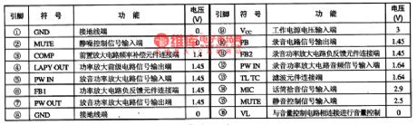
BA5208AF is an integrated 2-channle amplifier circuit of recording/reproduceing produced by Toyo Corp., Japan, which is widely used in stereo equipment, such as low-voltage walk-man, repeater and so on.BA5208AF contains sub-circuits of microphone amplifier, reproducing signal amplifier, recording amplifier and other function support circuits. This IC is in 16-lead dual-line package, whose pin functions and data of the circuit are listed in Table 1.
Table 1 pin functions and data of BA5208AF (View)
View full Circuit Diagram | Comments | Reading(807)
| Pages:1877/2234 At 2018611862186318641865186618671868186918701871187218731874187518761877187818791880Under 20 |
Circuit Categories
power supply circuit
Amplifier Circuit
Basic Circuit
LED and Light Circuit
Sensor Circuit
Signal Processing
Electrical Equipment Circuit
Control Circuit
Remote Control Circuit
A/D-D/A Converter Circuit
Audio Circuit
Measuring and Test Circuit
Communication Circuit
Computer-Related Circuit
555 Circuit
Automotive Circuit
Repairing Circuit