
Circuit Diagram
Index 1872
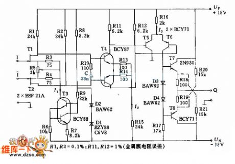
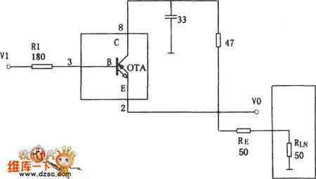
Simplified motor sports photoelectric positioning control circuit diagram
Published:2011/5/17 1:21:00 Author:Ecco | Keyword: Simplified, motor sports , photoelectric positioning control
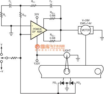

Figure 1 shows the circuit with the simple and basic design in order to achieve position control, it uses a pair of photodiodes connected in parallel with the the fast response time. Thus it achieves a system with small number of components, it has high reliability, accuracy and repeatability under clearly defined work environment. The circuit shown as the Figure 1 uses a power op amp to combine differential output of a pair of photodiodes, and it drives the direction of motor rotation to the right until the two photoelectric currents are equal, thus it achieves position control order.
(View)
View full Circuit Diagram | Comments | Reading(573)
Central Air Conditioner Geothermal All-In-One Device System Circuit
Published:2011/5/17 1:42:00 Author:Robert | Keyword: Central Air Conditioner, Geothermal, All-In-One Device System
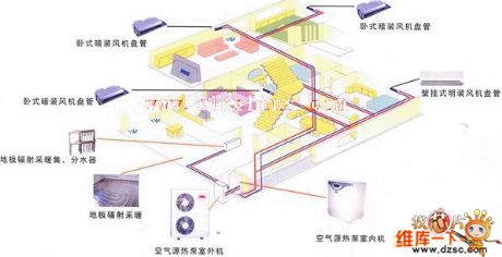
The Central Air Conditioner Geothermal All-In-One Device System Circuit is shown below.
(View)
View full Circuit Diagram | Comments | Reading(836)
Triode Transistor PE110F40 Internal Circuit
Published:2011/5/17 1:17:00 Author:Robert | Keyword: Triode Transistor, Internal
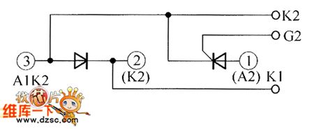
The Triode Transistor PE110F40 Internal Circuit is shown in the picture below.
(View)
View full Circuit Diagram | Comments | Reading(504)
FET Transistor Operational Amplifier Circuit
Published:2011/5/17 1:41:00 Author:Robert | Keyword: FET Transistor, Operational Amplifier
The FET Transistor Operational Amplifier Circuit is shown below.
(View)
View full Circuit Diagram | Comments | Reading(903)
Xiangxuehai Brand BCD-245 Refrigerator Circuit
Published:2011/5/17 1:39:00 Author:Robert | Keyword: Xiangxuehai Brand, Refrigerator
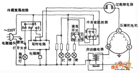
The Xiangxuehai Brand BCD-245 Refrigerator Circuit is shown below.
(View)
View full Circuit Diagram | Comments | Reading(598)
Speaker Overload Protection Circuit
Published:2011/5/16 8:19:00 Author:Robert | Keyword: Speaker, Overload, Protection
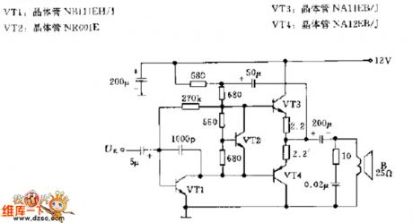
The Speaker Overload Protection Circuit is shown below.
(View)
View full Circuit Diagram | Comments | Reading(1805)
DLAC Control System Principle Circuit
Published:2011/5/17 1:18:00 Author:Robert | Keyword: DLAC, Control System, Principle
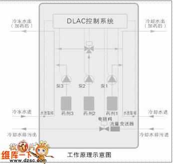
The DLAC Control System Principle Circuit is shown below.
(View)
View full Circuit Diagram | Comments | Reading(564)
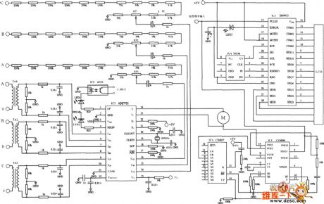
Three-Phase Electric Energy Metering System ADE7752 Typical Application Circuit
Published:2011/5/17 1:15:00 Author:Robert | Keyword: Three-Phase, Electric Energy Metering System, Application
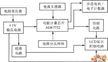
The first picture shows the electric energy meter composed of ADE7752 diagram.
The second picture shows the electric energy meter composed of ADE7752 circuit.
(View)
View full Circuit Diagram | Comments | Reading(5105)
Central Air Conditioner Geothermal All-In-One Device System Circuit (2)
Published:2011/5/17 1:35:00 Author:Robert | Keyword: Central Air Conditioner, Geothermal, All-In-One Device System
The Central Air Conditioner Geothermal All-In-One Device System Circuit (2) is shown below.
(View)
View full Circuit Diagram | Comments | Reading(839)
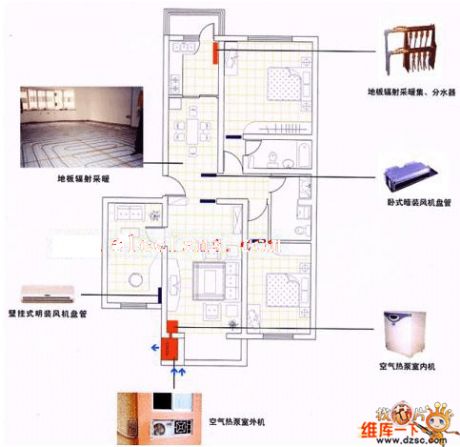
Xinfeng Geothermal Central Air Conditioner Working Principle Circuit
Published:2011/5/17 1:24:00 Author:Robert | Keyword: Xinfeng, Geothermal, Central Air Conditioner, Working Principle
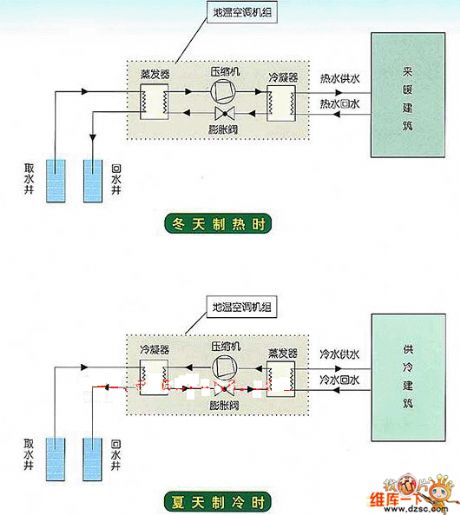
The Xinfeng Geothermal Central Air Conditioner Working Principle Circuit is shown below. The first shows heating in winter, the second shows the cooling in summer.
(View)
View full Circuit Diagram | Comments | Reading(1414)
Electronic Fishing Device Circuit
Published:2011/5/16 7:29:00 Author:Robert | Keyword: Electronic, Fishing Device
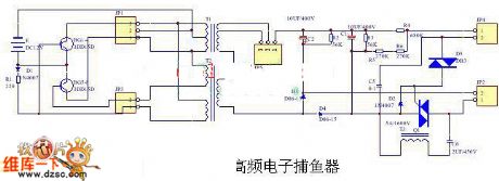
The Electronic Fishing Device Circuit is shown below.
(View)
View full Circuit Diagram | Comments | Reading(2078)
Home Gas Safety Alarm Device Principle Circuit
Published:2011/5/16 9:29:00 Author:Robert | Keyword: Home, Gas, Safety, Alarm Device
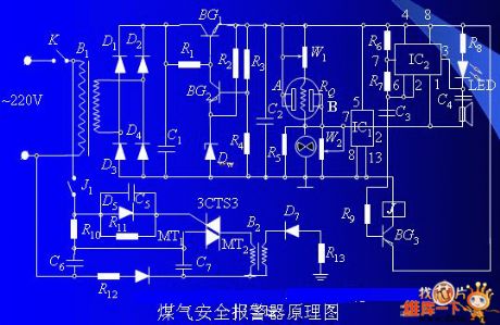
One part is the gas alarm device which would alarm before the gas density getting to the limit. The other part is a open negative ion generator whose function is generating air negative ion automatically. So the harmful ingredients carbon monoxide of the gas can react to the ozone (O3) in the air negative ion and this process produces harmless carbon dioxide.
The Home Gas Safety Alarm Device Principle Circuit is shown below.
(View)
View full Circuit Diagram | Comments | Reading(1286)
Yueda KIA Chassis Circuit
Published:2011/5/17 1:31:00 Author:Robert | Keyword: Yueda, KIA, Chassis
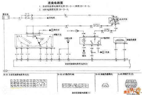
The Yueda KIA Chassis Circuit is shown below. (1)For automatic speed-variator circuit please see picture 25-2-1 and picture 25-2-2. (2)For ABS circuit please see picture 25-2-3.
(View)
View full Circuit Diagram | Comments | Reading(482)
Temperature Control Circuit With Upper And Lower Limits
Published:2011/5/16 9:59:00 Author:Robert | Keyword: Upper And Lower Limits, Temperature, Control
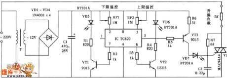
The Temperature Control Circuit With Upper And Lower Limits is shown below.
(View)
View full Circuit Diagram | Comments | Reading(848)
Ultra-Wide Bandwidth Large-Current Buffer Circuit
Published:2011/5/16 9:43:00 Author:Robert | Keyword: Ultra-Wide Bandwidth, Large-Current Buffer
The Ultra-Wide Bandwidth Large-Current Buffer Circuit is shown in the picture below. This circuit is a large-current buffer which can achieve bandwidth of 350~460MHz. This circuit uses the wideband transconductance amplifier OPA606. When the output voltage is +/-10V, its output current can be +/-10mA (typical), and the short current is +/-20mA (typical).
(View)
View full Circuit Diagram | Comments | Reading(1009)
BA3818F-the integrated circuit of voltage comparator
Published:2011/5/14 3:36:00 Author:Borg | Keyword: integrated circuit, voltage comparator
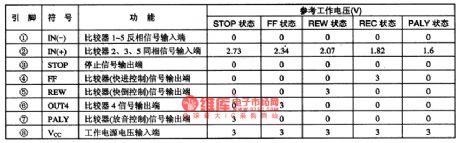
BA3818F is a voltage comparator produced by Toyo Corp.,Japan, which is widely used in all types of walk-man, stereos, TV sets and computer screens to compare the voltage amplifiers.BA3818F contains voltage comparator circuits and other additional function circuits, which is in 8-lead dual in-line plastic package, and it is used in Aiwa high-class walk-man. The pin functions and data are listed in Table 1.
Table 1 pin functions and data of BA3818F (View)
View full Circuit Diagram | Comments | Reading(927)
The integrated circuit of single door stereo radios
Published:2011/5/14 4:18:00 Author:Borg | Keyword: integrated circuit, single door, stereo radios
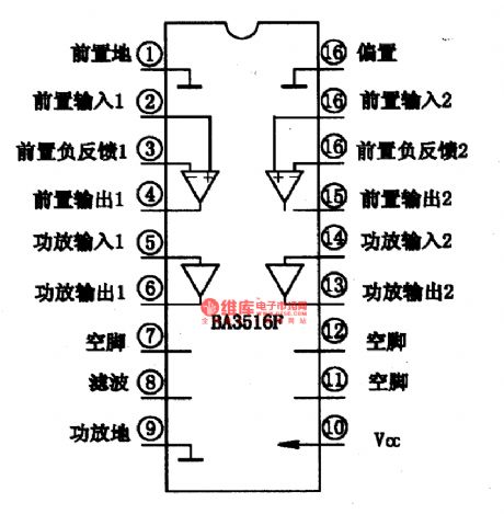
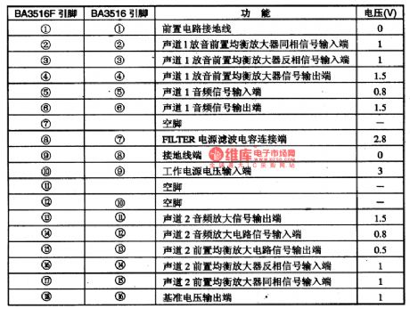
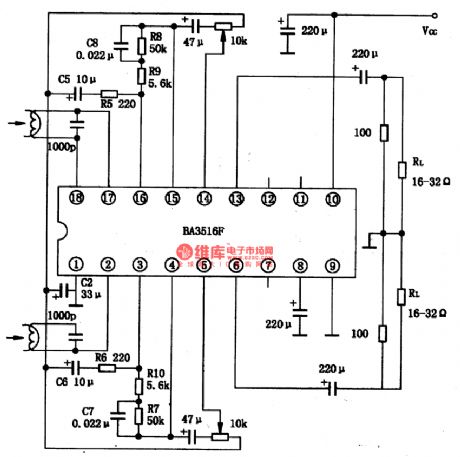
BA3516、BA3516 is an integrated circuit of single door stereo radios produced by Toyo Power Tool Corp.,Japan, which is commonly used in stereos, especially in walk-man, apart from Aiwa, sometimes, Sony, Phillips and local walk-man also use it.1.the internal circuit of BA3516 and BA3516F BA3516 is in two packages, of which BA3516 is in 16-lead dual in-line plastic package, while BA3516F is in 18-lead dual in-line plastic package. The two internal circuits are almost the same.
(View)
View full Circuit Diagram | Comments | Reading(1112)
The fault code of 42 detection circuit of Daewoo ESPERO
Published:2011/5/16 21:05:00 Author:Borg | Keyword: fault code, detection circuit
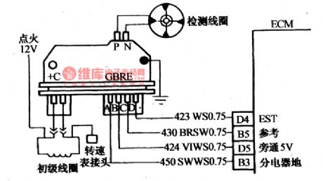
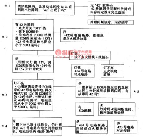
The fault of 42 represent the circuit (EST) is abnormal when electric ignition of the system is igniting. When the engine starts, the igniting module will send spindle position and rotating speed signals (through No.430 circuit ) to ECM. As long as the rotating speed of the engine is less than 400/min, the igniting time is under control of igniting module; and when the rotating speed of the engine is more than 400r/mm, the computer ECM will give No. 424 circuit a 5V reference voltage and shift the igniting time control to EST terminal, then No. 423 circuit will control the igniting time.The voltage on EST is changing (see as Figure 22 and Figure 6)]
(View)
View full Circuit Diagram | Comments | Reading(2102)
The fault code of 35 detection circuit of Daewoo ESPERO
Published:2011/5/16 22:14:00 Author:Borg | Keyword: fault code, detection circuit, Daewoo ESPERO
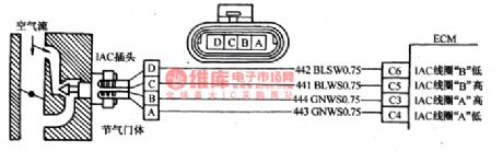
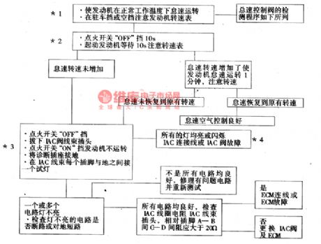
Fault code of 35 represents that the idling speed control system is malfunctioning(IAC). ECM pulse is called step frequency . The idling speed air control circuit is as shown in Figure 21.·adding idling speed--ECM sends enough step frequency to hold back IAC valve and allow more air to flow across idling speed tube but not across throttle valve, when the idling speed reaches proper rotating speed, then step frequency will be raised.·reducing idling speed--ECM sends enough step frequency to stick out IAC valve and allow less air to flow across the throttle valve--lateral idling speed tube, then step frequency needs to be reduced.
(View)
View full Circuit Diagram | Comments | Reading(879)
The electric spray system control circuit of Santana 200GLi AFE petrol engine(1)
Published:2011/5/16 8:24:00 Author:Borg | Keyword: electric spray system, control circuit, Santana
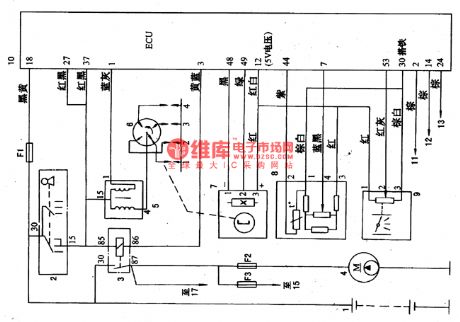
Figure 1 The electric spray system (power supply, iginitor) control circuit of Santana 200GLi AFE engine1-battery; 2-igniting switch; 3-oil pump relay; 5-igniting coil; 6-electricity distributor; 7-Hall spindle position TN signal generator (in electricity distributor); 8-admission temperature and pressure sensor; 9-throttle position sensor; 10-computer(ECU) controller; 11-ground connection of igniting coil; 12-ground connection of oil jet; 13-ground connection of computer controller; 14-explosive sensor; 15-oxygen sensor(including heater); 16-coolant temperature sensor; 17-the oil jet of No.1 cylinder (View)
View full Circuit Diagram | Comments | Reading(1179)
| Pages:1872/2234 At 2018611862186318641865186618671868186918701871187218731874187518761877187818791880Under 20 |
Circuit Categories
power supply circuit
Amplifier Circuit
Basic Circuit
LED and Light Circuit
Sensor Circuit
Signal Processing
Electrical Equipment Circuit
Control Circuit
Remote Control Circuit
A/D-D/A Converter Circuit
Audio Circuit
Measuring and Test Circuit
Communication Circuit
Computer-Related Circuit
555 Circuit
Automotive Circuit
Repairing Circuit