
Circuit Diagram
Index 1865
Common Positive Power Supply Long Distance Transmission Circuit Composed Of LM35DZ Celsius Temperature Sensor
Published:2011/5/17 9:21:00 Author:Robert | Keyword: Common Positive Power Supply, Long Distance, Transmission, Celsius, Temperature Sensor
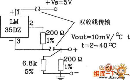
TheCommon Positive Power Supply Long Distance Transmission Circuit Composed Of LM35DZ Celsius Temperature Sensor is shown in the picture below.
(View)
View full Circuit Diagram | Comments | Reading(812)
Detection 4 ~ 20mA loop instrument amplifier (ISO120,XTR101)circuit diagram
Published:2011/5/16 20:43:00 Author:Ecco | Keyword: Detection , 4mA, 20mA, loop instrument , amplifier
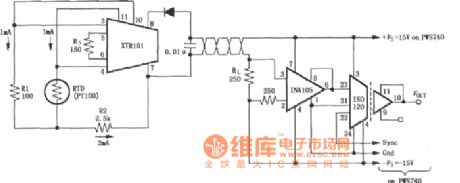
The RTDs isolated detection 4 ~ 20mA loop instrument amplifier circuit composed of ISO120 and INA105, XTR101 instrumentation amplifier is shown as the chart. Resistance temperature detector (RTD) can test temperature changing, the temperature changing can be changed into electrical signals which is input current loop amplifier XTR101, XTR101 transforms it into the 4 ~ 20mA current output, and the 4 ~ 20mA current is changed into voltage signal on the resistor RL by the twisted pair wires passing, and then amplified by the INA105 and sent to the isolation amplifier ISO120, and then it is isolated, amplified and output by ISO120. The main feature of the circuit is that the circuit uses XTR101 to transforme the input into 4 ~ 20mA current, the current signal can be transmitted in long distance, and it is not easy to get interference.
(View)
View full Circuit Diagram | Comments | Reading(1970)
Celsius Thermometer Circuit Composed Of LM35DZ Celsius Temperature Sensor
Published:2011/5/17 9:06:00 Author:Robert | Keyword: Celsius, Thermometer, Temperature Sensor
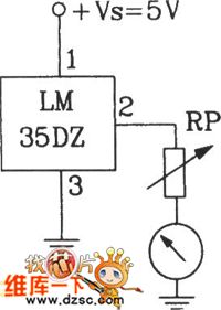
The Celsius Thermometer Circuit Composed Of LM35DZ Celsius Temperature Sensor is shown below.
(View)
View full Circuit Diagram | Comments | Reading(1466)
Rolling Massage Device Principle Circuit
Published:2011/5/17 9:01:00 Author:Robert | Keyword: Rolling, Massage Device, Principle
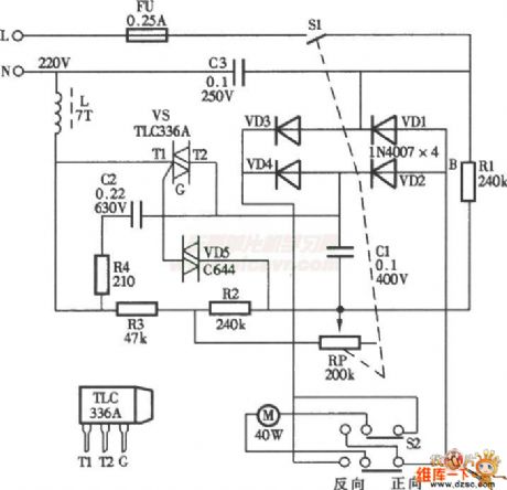
The Rolling Massage Device Principle Circuit is shown below.
(View)
View full Circuit Diagram | Comments | Reading(957)
Current Flowing After Boot Circuit
Published:2011/5/17 8:54:00 Author:Robert | Keyword: Current Flowing, Boot
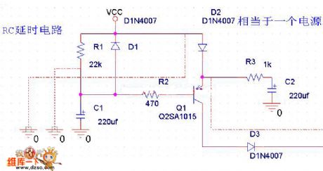
The Current Flowing After Boot Circuit is shown below.
(View)
View full Circuit Diagram | Comments | Reading(801)
Testing 4 ~ 20mA loop equipment amplifier (ISO122P/124, XTR101, RCV420) circuit diagram
Published:2011/5/17 2:33:00 Author:Ecco | Keyword: testing, 4 ~ 20mA, loop equipment , amplifier
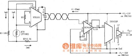
The RTDs isolated detection 4 ~ 20mA loop instrument amplifier circuit composed of ISO122P/124 and loop current transmission circuit XTR101, the loop current receiver circuit CV420 is shown as the chart. Resistance temperature detector (RTD) can test temperature changing, the temperature changing can be transformed into electrical signals input by XTR101, and then it is changed into the 4 ~ 20mA current output by XTR101, and then it transfered by the twisted pair and received by RCV420 , then the 4 ~ 20mA current is changed into voltage signal, the voltage signal is amplified and sent to isolation amplifier ISO122P, amplified, isolated by the ISO122P and it outputs 0 ~ 5V voltage.
(View)
View full Circuit Diagram | Comments | Reading(2105)
Current Flowing After Boot Circuit (2)
Published:2011/5/17 8:53:00 Author:Robert | Keyword: Current Flowing, Boot
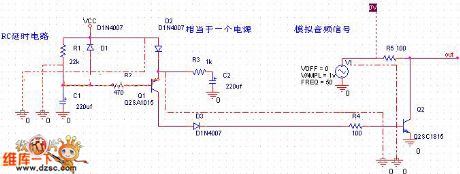
The Current Flowing After Boot Circuit (2) is shown below.
(View)
View full Circuit Diagram | Comments | Reading(633)
Precision Celsius Thermometer Circuit Composed Of SL134 Integrated Temperature Sensor
Published:2011/5/17 8:44:00 Author:Robert | Keyword: Precision, Celsius Thermometer, Integrated, Temperature Sensor
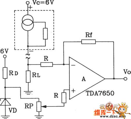
The Precision Celsius Thermometer Circuit Composed Of SL134 Integrated Temperature Sensor is shown below.
(View)
View full Circuit Diagram | Comments | Reading(1221)
EGC right leg drive amplifier circuit diagram with defibrillator shock protection and calibrator
Published:2011/5/17 3:00:00 Author:Ecco | Keyword: EGC, right leg , drive amplifier , defibrillator shock protection , calibrator
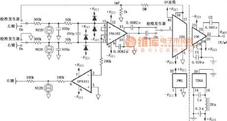
EGC right leg drive amplifier circuit with defibrillator shock protection and calibrator composed of INA102 and ISO106 is shown as the chart. The circuit has three ganged SPDT switches, the switch being connected to the calibration shows calibration state, the on shows the circuit being in measured state. When the circuit is in the measurement state, the output signal of left and right arm is amplified by INA102 and sent to the ISO106, and it is isolated, amplified and output by by ISO106. The output signal of of op amp OPA121 is the drive signal of right leg. When the circuit is in the calibration state, 5V reference voltage is divided by 5MΩ and 1kΩ resistors, it attenuates 5000 times.
(View)
View full Circuit Diagram | Comments | Reading(4076)
Triode Transistor KK160F80 Internal Circuit
Published:2011/5/17 8:42:00 Author:Robert | Keyword: Triode Transistor, Internal
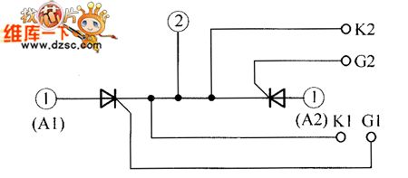
The Triode Transistor KK160F80 Internal Circuit is shown below.
(View)
View full Circuit Diagram | Comments | Reading(719)
MAX4188/4189/4190 current-feedback amplifier circuit diagram with high-speed banned mode
Published:2011/5/17 3:09:00 Author:Ecco | Keyword: current-feedback , amplifier, high-speed , banned mode
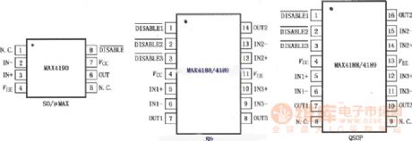
MAX4188/4189/4190 low-power current feedback amplifier has the low conversion transient state and high-speed enable / disable time. Three pieces of MAX4188 and single MAX4190 have closed-loop gain with +2 (6dB) or greater compensation to provide 200MHz-3dB bandwidth and 185MHz bandwidth respectively. Three pieces of MAX4189has closed-loop gain with +1 (0dB) or greater compensation to provide 250MHz-3dB bandwidth. The 0.1dB gain flatness of these amplifiers can reach 80MHz, differential gain is 0.03% and phase error is 0.055, all of these features make it be an ideal choice for video applications.
(View)
View full Circuit Diagram | Comments | Reading(511)
circuit diagram of electron gun DC high voltage power supply
Published:2011/5/17 8:21:00 Author:Ariel Wang | Keyword: electron gun, DC, high voltge

The circuit diagram of electron gun DC high voltage power supply is as below:
(View)
View full Circuit Diagram | Comments | Reading(1187)
Wireless remote control switch circuit 7
Published:2011/5/9 0:54:00 Author:Rebekka | Keyword: Wireless remote control switch
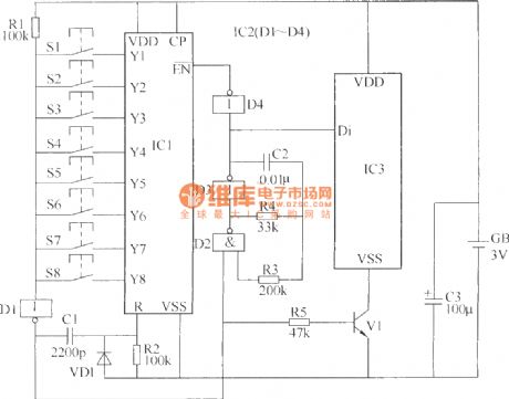
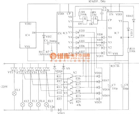
The wireless remote control switch circuit is composed of the wireless remote control transmitter and receiver wireless remote control circuit. The radio remote control transmitter circuit is composed of the pulse encoder circuit and radio transmitter circuit. It is shown as above.
Components selectionR1 ~ R20 uses 1/4W carbon film resistors or metal film resistors; R21 chooses 1/2W metal film resistors. C1 and C4 use high-frequency ceramic capacitors; C2 and C6 use monolithic capacitors; C3 and C7, C8 use electrolytic capacitors voltage 16V; C5 uses voltage 400V CBB capacitors. VD1 ~ VD13 and VD16 ~ VD20 use 1N4148 silicon switch diode; VD14 and VD15 use 1N4007 type silicon rectifier diodes.VS uses 1W, 6.2V silicon voltage regulator diodes. V1 ~ V6 use S9013 or C8050, S8050, 3DG9013, 3DG8050 silicon NPN transistor. VT1 ~ VT5 use TLC336A (3A, 600V) type bidirectional thyristor. IC1, IC5 and IC7 use CC4017 or CD4017 type decimal counting / pulse divider circuits; IC2 and IC6 use CC4011 or CD4011 type four NAND gate integrated circuit ; IC3 uses T630 type radio transmitter IC; IC4 uses T631 type radio receiver integrated circuit.S1 ~ S8 use tiny moving together (normally open) button. GB uses two 5 batteries. (View)
View full Circuit Diagram | Comments | Reading(1877)
Toyota Land Cruiser 70 light off-road vehicle moon roof and sun roof circuit diagram
Published:2011/5/8 12:24:00 Author:Rebekka | Keyword: Toyota Land Cruiser, light off-road vehicle
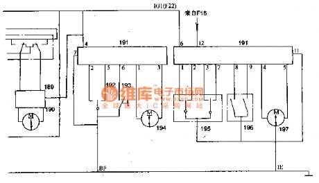
Toyota Land Cruiser 70 light off-road vehicle moon roof and sun roof circuit diagram.
189 right window switch ; 190 the right doors and windows motor; 191 moon-shaped roof control relay; 192 sun roof switch; 193 sun-shaped roof of a limit switch; 194 sun roof motor; 195 moon-shaped roof off; 196 moon-shaped roof limit switches; 197 moon-shaped roof motor; FI-F22 fuse; F16 connection 3OC hungry fuse.
(View)
View full Circuit Diagram | Comments | Reading(1050)
TL494 Internal function block diagram and basic unit circuit diagram
Published:2011/5/15 8:47:00 Author:Rebekka | Keyword: Internal function block diagram, basic unit circuit
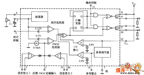
The system uses a PWM generator TL494 producd by Texas Instruments.It is a typical fixed-frequency PWM control IC, which contains all the required control switching power supply function. It can be used as a single-ended forward double tube, half bridge type, full bridge type switching power supply control system, the basic circuit units is shown as above. (View)
View full Circuit Diagram | Comments | Reading(3747)
High input impedance in-phase differential amplifier circuit composed of OP200
Published:2011/5/16 10:02:00 Author:Rebekka | Keyword: High input impedance, in-phase differential amplifier
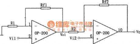
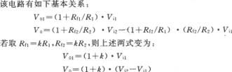
(View)
View full Circuit Diagram | Comments | Reading(620)
Automatic zeroing amplifier circuit composed of OPA2111BM
Published:2011/5/16 9:52:00 Author:Rebekka | Keyword: Automatic zeroing amplifier
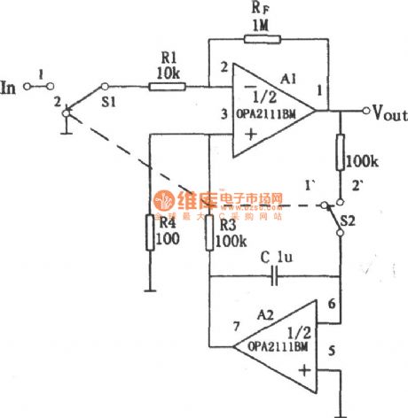
Automatic zeroing amplifier circuit is shown as above. OPA2111 low bias (≤ ± 4pA), its setting up time is very short (1μs established to 0.01% accuracy), the noise is very small (8nV / (Hz) 1 / 2, 10kHz). It passes the automatic zeroing set can keep the offset voltage less than 5μV. Zero drift ≤ 0.028μV / C, converting to the input terminal and the zero potential regulation rate is ≤ 2μV / s. If you appropriately reduce the integration capacitor C, the zero potential adjusting speed can be improved. The voltage amplification factor is Av =- RF/R1 =- 100. (View)
View full Circuit Diagram | Comments | Reading(707)
BA6227-the speed-stable integrated circuit
Published:2011/5/13 7:12:00 Author:Borg | Keyword: speed-stable, integrated circuit
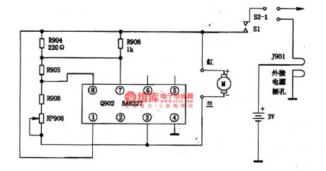
BA6227 is a speed-stable integrated circuit produced by Toyo Corp.,Japan, which is used to drive and regulate the motor.1.the typical circuit of BA6227 The typical application circuit of BA6227 chips is as shown in Figure 1.
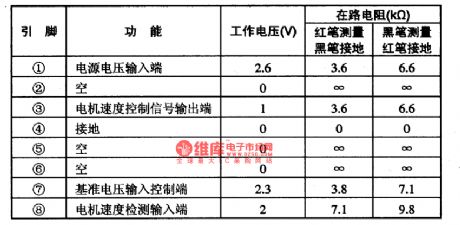
Figure 1 The typical application circuit of BA6227 chipsBA6227 is in 8-lead dual-line package, whose pin functions and data are listed in Table 1.
Table 1 pin functions and data of BA6227 chips (View)
View full Circuit Diagram | Comments | Reading(2102)
Op amp power supply voltage polarity reverse protection circuit diagram
Published:2011/5/17 3:21:00 Author:Rebekka | Keyword: Op amp, power supply voltage, polarity reverse protection
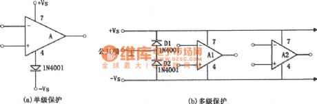
The protection circuit of the op amp power supply reverse polarity is shown in figure (a), (b). Figure (a) is protection circuit of the single-stage amplifier, Figure (b) is the multi-stage amplifier circuit protection circuit. If the integrated operational amplifier without power polarity protection. The power supply voltage polarity is reversed, a destructive current will pass the chip (usually when the chip is in normal operation, there will be a large current passes the reverse-biased diode). The principle of the protection circuit is very simple. For figure (a), it uses the one-way conductive of the diode, so that the reversed power supply voltage can not be added to the integrated operational. For figure (b), it is concentrated protection circuit. When the power supply voltage is reversed, the diodes D1 and D2 turns on. (View)
View full Circuit Diagram | Comments | Reading(1670)
Op amp power supply over-voltage protection circuit diagram
Published:2011/5/17 3:44:00 Author:Rebekka | Keyword: Over-voltage protection , Op amp power supply
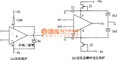
Power supply over-voltage protection circuit is shown as above. Figure (a) is simple and practical over-voltage protection circuit, which uses Zener diode Dz to limit the integrated operational amplifier supply voltage within the safe voltage limit. The selection method of the regulator of the operating voltage can be based on the following formula: Vz ≤ 2Vsmax. Normally Vz should be close or equal to the total power supply voltage, its current limiting resistor R should use high-power resistance, and resistance value should ensure the voltage regulator tube is able to work properly. Figure (b) shows the two functions that overvoltage protection and transient voltage protection. When it is in normal operation mode, the tube pressure of J1 and J2 should be decrease, ± VSD value is low, so the two regulators Dz1 and Dz2 do not work, so none of them is breakdown. (View)
View full Circuit Diagram | Comments | Reading(1988)
| Pages:1865/2234 At 2018611862186318641865186618671868186918701871187218731874187518761877187818791880Under 20 |
Circuit Categories
power supply circuit
Amplifier Circuit
Basic Circuit
LED and Light Circuit
Sensor Circuit
Signal Processing
Electrical Equipment Circuit
Control Circuit
Remote Control Circuit
A/D-D/A Converter Circuit
Audio Circuit
Measuring and Test Circuit
Communication Circuit
Computer-Related Circuit
555 Circuit
Automotive Circuit
Repairing Circuit