
Circuit Diagram
Index 1863
Four Line Light Control Circuit
Published:2011/5/17 8:20:00 Author:Robert | Keyword: Four Line, Light, Control
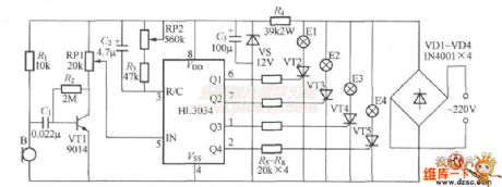
The Four Line Light Control Circuit is shown below.
(View)
View full Circuit Diagram | Comments | Reading(723)
Buick Seat Backrest Adjustment Circuit
Published:2011/5/17 7:24:00 Author:Robert | Keyword: Buick, Seat, Backrest, Adjustment
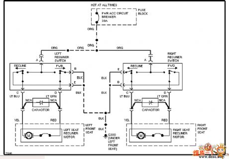
The Buick Seat Backrest Adjustment Circuit is shown below.
(View)
View full Circuit Diagram | Comments | Reading(560)
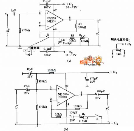
Wideband Amplifier Circuit
Published:2011/5/17 7:21:00 Author:Robert | Keyword: Wideband, Amplifier
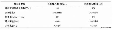
The Wideband Amplifier Circuit is shown below. The picture (a) and picture (b) have not only the differences on the input signal's symbol, but also the differences on the input impedance |Ze|. Its main technical data is listed below.
Amplifier TypeOut-phase input port (picture a) In-phase input port (picture b)
Low frequency closed-loop amplification factor |Vo'| 100 100
3dB bandwidth b >20MHz >20MHz
Supply Voltage Up=-Un 8V 8V
Input impedance |Ze| 111Ω >100kΩ
Load Capacitance Cl <=22pF <=22pF
(View)
View full Circuit Diagram | Comments | Reading(575)
Water Temperature Automatically Control Device Circuit
Published:2011/5/17 7:22:00 Author:Robert | Keyword: Water Temperature, Automatically Control Device
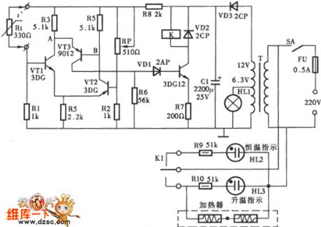
The Water Temperature Automatically Control Device Circuit is shown below.
(View)
View full Circuit Diagram | Comments | Reading(1287)
Buick Passive Seat Safety System Circuit
Published:2011/5/17 7:13:00 Author:Robert | Keyword: Buick, Passive, Seat, Safety System
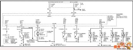
The Buick Passive Seat Safety System Circuit is shown below.
(View)
View full Circuit Diagram | Comments | Reading(474)
Half-Wave Rectifier Circuit
Published:2011/5/17 7:11:00 Author:Robert | Keyword: Half-Wave, Rectifier

The Half-Wave Rectifier Circuit is shown below.
(View)
View full Circuit Diagram | Comments | Reading(3074)
Wideband Operational Amplifier Circuit
Published:2011/5/17 7:10:00 Author:Robert | Keyword: Wideband, Operational Amplifier
The Wideband Operational Amplifier Circuit is shown below.
(View)
View full Circuit Diagram | Comments | Reading(842)
Voltage Doubling Rectifier Circuit
Published:2011/5/17 7:08:00 Author:Robert | Keyword: Voltage Doubling, Rectifier
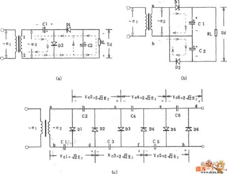
The Voltage Doubling Rectifier Circuit is shown below.
(View)
View full Circuit Diagram | Comments | Reading(805)
Buick Headlight Circuit (With DRL)
Published:2011/5/17 7:07:00 Author:Robert | Keyword: Buick, Headlight Circuit, DRL
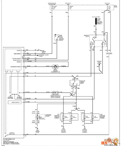
The Buick Headlight Circuit (With DRL) is shown below.
(View)
View full Circuit Diagram | Comments | Reading(567)
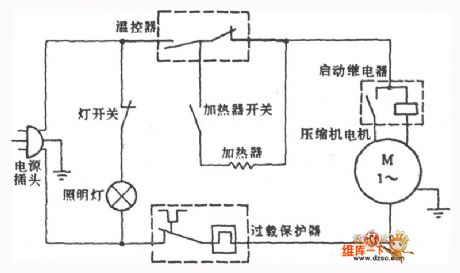
Huari Brand BC-150 Refrigerator Circuit
Published:2011/5/17 7:05:00 Author:Robert | Keyword: Huari Brand, Refrigerator
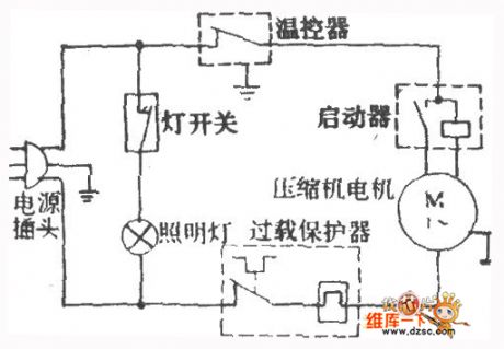
The Huari Brand BC-150 Refrigerator Circuit is shown below.
(View)
View full Circuit Diagram | Comments | Reading(626)
Adaptive adjustable power supply circuit diagram
Published:2011/5/16 20:19:00 Author:Ecco | Keyword: Adaptive , adjustable , power supply
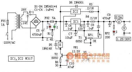
In the circuit, the T2, D5, VW1, R5, R6, C10 and K constitute adaptive switching action circuit. When the output is lower than 14V, VW1 stops due to lacking of sufficient breakdown voltage, the circuit has no current, T2 cuts off, K does not pull, the contact K is in the normal position, the input current is AC 14V. Conversely when the output voltage is higher than 14V, VW1 and T2 are conducted, the relay K pulls in, 28V AC is put in the circuit. This ensures that the input voltage and output voltage difference is not greater than 15V, then, the typically value of W317 output current is 2.2A.
(View)
View full Circuit Diagram | Comments | Reading(963)
Buick Front Wiper And Washer Circuit
Published:2011/5/17 7:04:00 Author:Robert | Keyword: Buick, Front Wiper, Washer
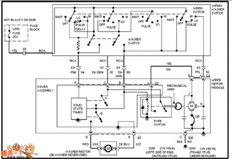
The Buick Front Wiper And Washer Circuit is shown below.
(View)
View full Circuit Diagram | Comments | Reading(822)
Full-Wave Rectifier Circuit
Published:2011/5/17 7:02:00 Author:Robert | Keyword: Full-Wave, Rectifier
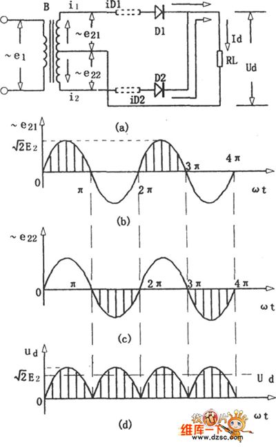
The Full-Wave Rectifier Circuit is shown below.
(View)
View full Circuit Diagram | Comments | Reading(1942)
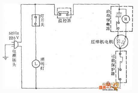
Huari Brand BCD-170,185,205 Refrigerator Circuit
Published:2011/5/17 7:00:00 Author:Robert | Keyword: Huari Brand, Refrigerator
The Huari Brand BCD-170,185,205 Refrigerator Circuit is shown below.
(View)
View full Circuit Diagram | Comments | Reading(663)
Buick External Light Circuit (Car)
Published:2011/5/17 6:59:00 Author:Robert | Keyword: Buick, External Light
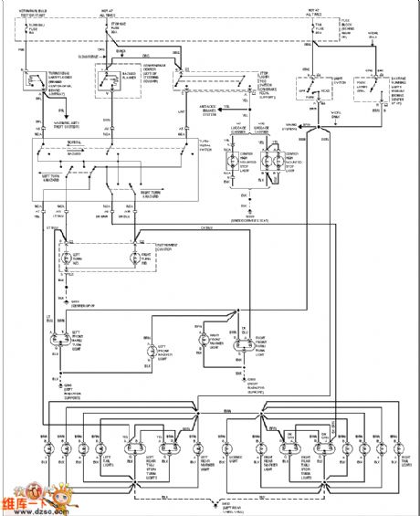
The Buick External Light Circuit (Car) is shown below.
(View)
View full Circuit Diagram | Comments | Reading(486)
Bridge Rectifier Circuit
Published:2011/5/17 6:57:00 Author:Robert | Keyword: Bridge, Rectifier
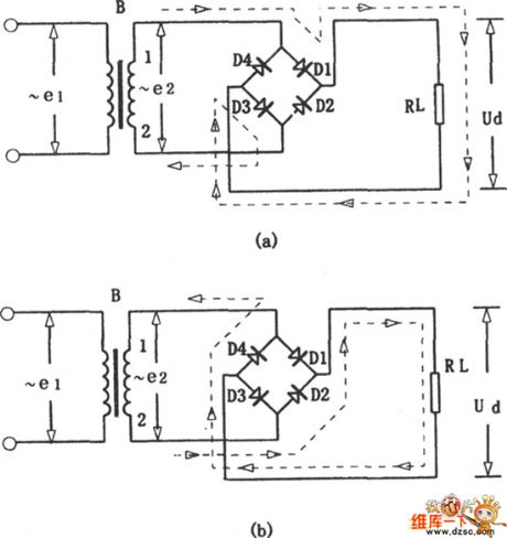
The Bridge Rectifier Circuit is shown below.
(View)
View full Circuit Diagram | Comments | Reading(1001)
Rongsheng Brand BY-103 Refrigerator Circuit
Published:2011/5/17 6:56:00 Author:Robert | Keyword: Rongsheng Brand, Refrigerator
The Rongsheng Brand BY-103 Refrigerator Circuit is shown below.
(View)
View full Circuit Diagram | Comments | Reading(540)
The single power changing into dual power circuit diagram by TDA2030
Published:2011/5/16 21:58:00 Author:Ecco | Keyword: single power , dual power
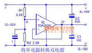
The circuit is shown as the chart, R1 and R2 with the equal resistance form a voltage divider, so that the upper and lower voltage are equal. The mid-point of the divider is connected to the op amp inverting input end, the op amp is connected as a voltage follower, so that the potential on O 'and O side is equal. O 'side is the virtual point, the place connected to input supply must be isolated. If the bipolar power supply is directly out from the R1, R2, the resistance of source is higher, the load capacity is poor, the practical value is little. After using the operational amplifier, two output powers have low internal resistance, the load capacity is strengthened.
(View)
View full Circuit Diagram | Comments | Reading(3675)
Buick Automatical Door Lock Circuit
Published:2011/5/17 6:54:00 Author:Robert | Keyword: Buick, Automatical Door Lock
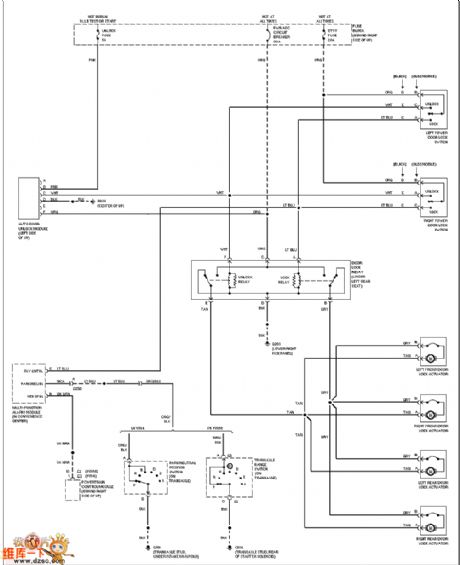
The Buick Automatical Door Lock Circuit is shown below.
(View)
View full Circuit Diagram | Comments | Reading(505)
Buick Air Conditioner Circuit
Published:2011/5/17 6:53:00 Author:Robert | Keyword: Buick, Air Conditioner
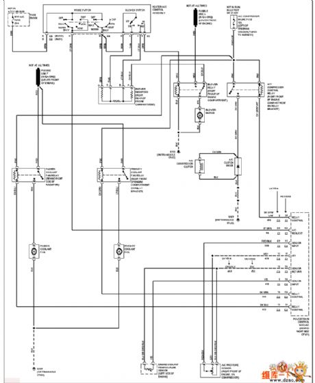
The Buick Air Conditioner Circuit is shown below.
(View)
View full Circuit Diagram | Comments | Reading(625)
| Pages:1863/2234 At 2018611862186318641865186618671868186918701871187218731874187518761877187818791880Under 20 |
Circuit Categories
power supply circuit
Amplifier Circuit
Basic Circuit
LED and Light Circuit
Sensor Circuit
Signal Processing
Electrical Equipment Circuit
Control Circuit
Remote Control Circuit
A/D-D/A Converter Circuit
Audio Circuit
Measuring and Test Circuit
Communication Circuit
Computer-Related Circuit
555 Circuit
Automotive Circuit
Repairing Circuit