
Circuit Diagram
Index 1866
The ECU terminal circuit of Xiali engine
Published:2011/5/13 9:09:00 Author:Borg | Keyword: ECU, terminal circuit, Xiali
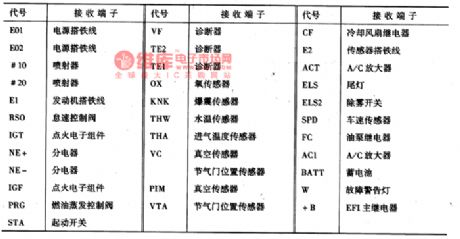
Thecontrolling computerterminal codes of 8A-FE are as shown in Figure 3
Figure 3 the ECU terminals of 8A-FE engine
(View)
View full Circuit Diagram | Comments | Reading(628)
Application input end zeroing circuit diagram
Published:2011/5/17 1:43:00 Author:Rebekka | Keyword: Application input end , zeroing circuit
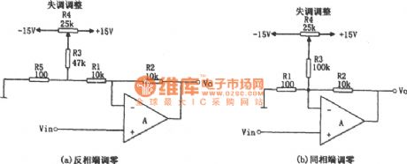
In figure (a), it uses a small resistor R5 connecting in the return circuit of R1, the offset voltage produced by R5 and R3 are added to the left end of R1.And the voltage will be divided by R1 and R2. So the offset voltage adjustment range is determined by the following formula: Offset voltage adjustment range = ± VD · (R5/R3) · (R2 / (Rl + R2)) (± VD = ± l5V).
According to the resistance value shown in figure (a) , the offset voltage adjustment range is: ± 15mV. R1 = R2. Therefore, the voltage gain of the circuit is low. Taking the R5 and R1 are in series into account , the voltage gain Av: Av = 1 + R2 / (Rl + R5) (View)
View full Circuit Diagram | Comments | Reading(801)
Ward Caller One
Published:2011/5/14 6:05:00 Author:Felicity | Keyword: Ward Caller,
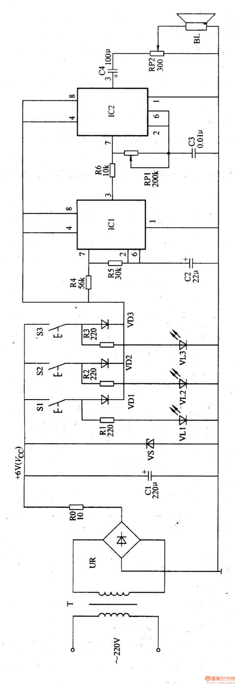
When the call buttons S1-S3 are not pressed, LED vl1-vl3 are all off. Oscillator A and B are both in the stop state lacking of work voltage, and the speaker BL is quiet.
When one of the call buttons is pressed, +6 voltage is provided to oscillator A and B through the button and the diode connected to it. And the BL issues a Du, du calling sound. At the same time while the button is pressed, the LED of the same branch is on.
Adjusting the resistance of RP1 can change the pitch of the calling sound.
Adjusting the resistance of RP2 can change the volume of BL. (View)
View full Circuit Diagram | Comments | Reading(526)
The circuit diagram of highly accurate current output integrated temperature sensor AD592 matching A/D converter
Published:2011/5/16 20:49:00 Author:Nicole | Keyword: current output, integrated temperature sensor, A/D converter
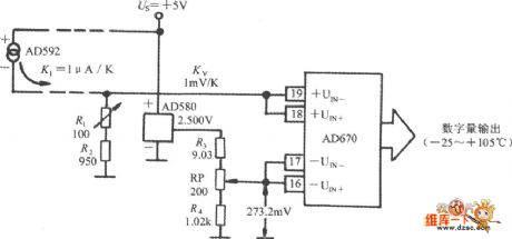
In microcontroller temperature measuring system, firstly, AD592 outputed analog is changed into digital by A/D converter, then it is sent to single chip and data processed. The AD592 matching A/D converter circuit is shown in the figure. It adopts a AD670 to transfer 8-bit A/D. AD670 is 4 terminal differential input, it contains input attenuator, instrumentation amplifier and 8-bit A/D converter of reference voltage source. The current signal exported by AD592 is transformed into voltage signal by R1 and R2, the voltage temperature coefficient is 1mV/℃.
(View)
View full Circuit Diagram | Comments | Reading(2290)
Cooling liquid level sensor circuit diagram
Published:2011/5/16 20:30:00 Author:Nicole | Keyword: cooling liquid level, sensor
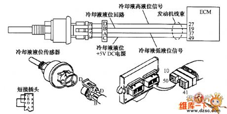
The cooling liquid level sensor circuit is shown in the figure.
In 49 terminal of motor wiring harness's 5V power line, the voltage is detected too high or too low, EOM is considered failure, these failures are recorded in the form of fault code 515 or 516, the yellow alarm indicator light is turned on. Whether the power voltage is too high or too low, it will lead to the motor loss the protection function of cooling liquid level.
(1)The motor wiring harness and cooling liquid level sensor connector terminal are checked, if it is damaged, it should be repaired.
(View)
View full Circuit Diagram | Comments | Reading(1535)
Multi-purpose automatic charger circuit diagram
Published:2011/5/16 21:43:00 Author:Ecco | Keyword: Multi-purpose , automatic , charger
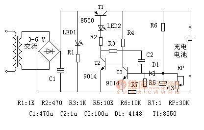
The circuit is designed for the single Ni-MH battery. In the figure: the electric supply is transformed by the transformer, rectified by the full-bridge, filtered by capacitor C1 and then it becomes DC current. LED1 is the power indicator, LED2 is the charging indicator light, T1 is the charging control transistor, which operates in the switching state; T2, T3 and capacitor C2 form a single stable trigger. R6 and RP constitutes a limited pressure sampling circuit, R7 is limiting the sampling resistor.
When the circuit gets power, if it does not connect to the battery, transistor T2 cuts off because of no base voltage, transistor T1 is also off, there is no voltage output. At this point only the power indicator light LED1 is lit.
(View)
View full Circuit Diagram | Comments | Reading(2220)
Automatic hand dryer 4
Published:2011/5/16 21:54:00 Author:Nicole | Keyword: hand dryer
The circuit work theory
This automatic hand dryer circuit is composed of power supply, infrared transmitting circuit, infrared signal process circuit, electric heater circuit and fan control circuit, the circuit is shown in the figure 9-127.
The power supply circuit is made of fuse FU, power switch S, power transformer T, rectifier diodes VD1-VD4, filter capacitors C1, C5, C6, resistor R13, power indication LED VL1 and three terminal regulator integrated circuit IC3.
The infrared transmitting circuit is made of infrared LED VU, resistors R7, R8, capacitor RP4, capacitor C4 and time base integrated circuit IC2.
(View)
View full Circuit Diagram | Comments | Reading(1760)
Infrared automatic hand washing device 2
Published:2011/5/16 22:55:00 Author:Nicole | Keyword: hand washing device
The circuit work theory
This infrared automatic hand washing device circuit is composed of power supply, infrared transmitting circuit, infrared receiving amplifier circuit and delay control circuit, the circuit is shown in the figure 9-120.
The power supply circuit is made of power transformer T, bridge rectifier UR, filter capacitor C4, current limiting resistor R7, power indication LED VL2 and three terminal regulator integrated circuit IC4.
The infrared transmitting circuit is made of infrared transmitting integrated circuit IC1, resistors R1-R3, capacitor C1, transistor V1 and infrared LED VL1.
The infrared receiving amplifier circuit consists of integrative infrared receiving integrated circuit IC2, resistors R4, R5 and transistor V2.
(View)
View full Circuit Diagram | Comments | Reading(1244)
Infrared automatic hand washing device 3
Published:2011/5/16 22:47:00 Author:Nicole | Keyword: hand washing device
The circuit work theory
This infrared automatic hand washing device circuit is composed of power supply, infrared transmitting circuit, infrared receiving circuit and control circuit, the circuit is shown in the figure 9-121.
The power supply circuit is made of fuse FU, power transformer T, bridge rectifier UR, filter capacitors C1, C2 and three terminal regulator integrated circuit IC1.
The infrared transmitting circuit is made of time base integrated circuit IC2, potentiometer RP, resistors R1, R2, capacitors C3, C4 and infrared LED VL.
The infrared receiving circuit consists of infrared light-sensitive transistor VD1, resistors R3, R4, capacitors C5-C7 and infrared receiving integrated circuit IC3.
(View)
View full Circuit Diagram | Comments | Reading(2854)
Infrared automatic hand washing device 4
Published:2011/5/16 22:34:00 Author:Nicole | Keyword: hand washing device
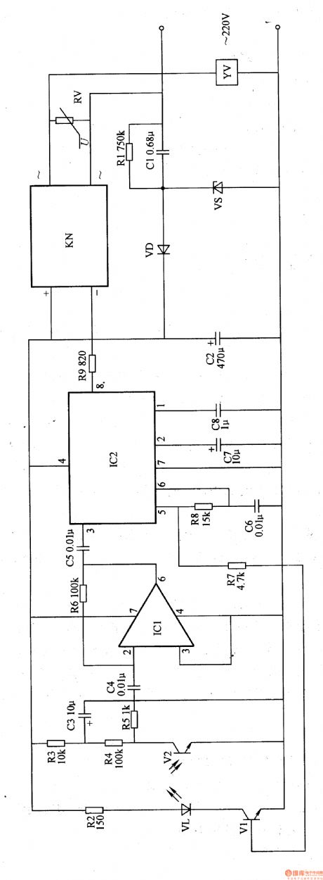
The circuit work theory
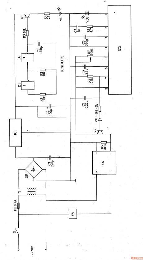
This infrared automatic hand washing device circuit is composed of power supply, infrared transmitting circuit, infrared receiving amplifier circuit and decoding control circuit, the circuit is shown in the figure 9-122.
The power supply circuit is made of capacitors C1, C2, resistor R1, voltage stabilizing diode VS and rectifier diode VD.
The infrared transmitting circuit is made of resistors R2, R7, infrared LED VL, transistor V1 and IC2's 5-foot internal circuit.
The infrared receiving amplifier circuit consists of resistors R3-R6, capacitors C3-C5, infrared light-sensitive transistor V2 and operational amplifier integrated circuit IC1.
(View)
View full Circuit Diagram | Comments | Reading(735)
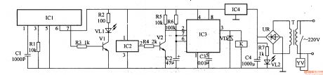
Infrared automatic hand washing device 5
Published:2011/5/16 22:16:00 Author:Nicole | Keyword: hand washing device
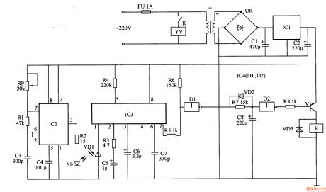
The circuit work theory
This infrared automatic hand washing device circuit is composed of power supply, infrared transmitting circuit, infrared receiving process circuit and control implement circuit, the circuit is shown in the figure 9-123.
The power supply circuit is made of power switch S, fuse FU, power transformer T, bridge rectifier UR, capacitors C1, C2 and three terminal regulator integrated circuit IC1.
The infrared transmitting circuit consists of not gate integrated circuit IC3(Dl、D2), resistors R1-R4, capacitor C3, transistor V1 and infrared LED VL.
The infrared receiving process circuit is composed of infrared photosensitive diode VD2, resistors R7, R8, potentiometer RP, capacitors C4-C7 and infrared process integrated circuit IC2.
The control implement circuit is made of resistors R5, R6, diode VD1, transistor V2, solid state relay KN and electromagnetism water valve YV.
(View)
View full Circuit Diagram | Comments | Reading(1039)
Automatic hand dryer 1
Published:2011/5/16 21:25:00 Author:Nicole | Keyword: hand dryer
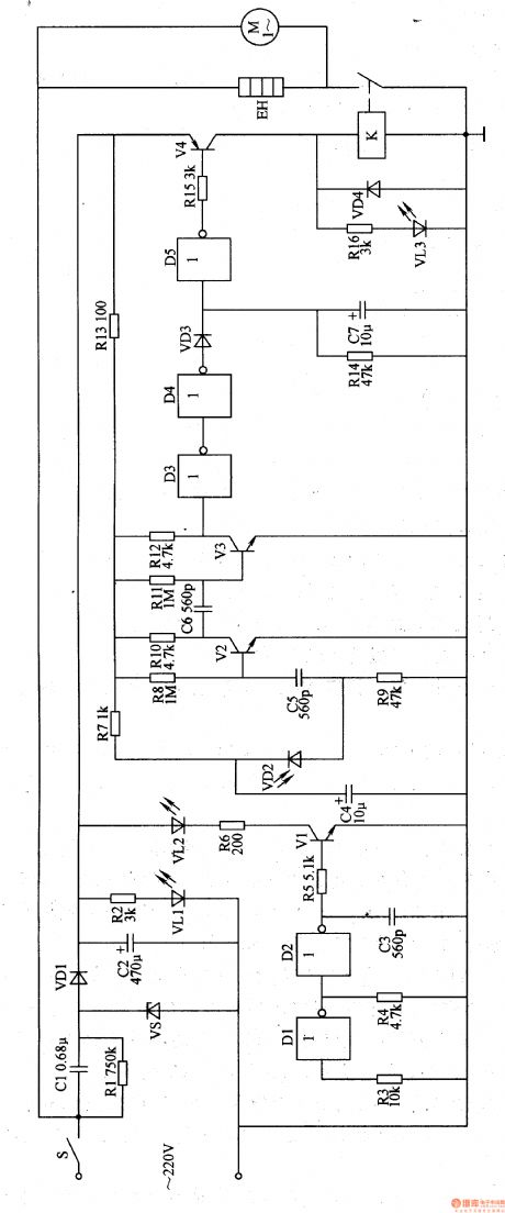
The circuit work theory
This infrared automatic hand dryer circuit is composed of power supply, infrared transmitting circuit, infrared receiving amplifier circuit, delay circuit and air heater control circuit, the circuit is shown in the figure 9-124.
The power supply is made of power supply switch S, depressurization capacitor C1, resistors R1, R2, voltage stabilizing diode VS, rectifier diode VD1, filter capacitor C2 and power indication LED VL1.
The infrared transmitting circuit is made of not gate integrated circuit IC(D1-D5) internal not gate D1, D2, resistors R3-R6, capacitor C3, transistor V1 and infrared LED VL2.
(View)
View full Circuit Diagram | Comments | Reading(995)
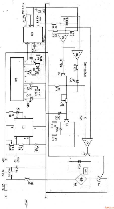
Automatic hand dryer 2
Published:2011/5/16 21:46:00 Author:Nicole | Keyword: hand dryer
The circuit work theory
This automatic hand dryer circuit is composed of power supply, infrared transmitting circuit, infrared receiving amplifier circuit, detector circuit and control circuit, the circuit is shown in the figure 9-125.
The power supply is made of fuse FU, power transformer T, bridge rectifier UR, filter capacitor C1-C4 and three terminal regulator integrated circuit IC1.
The infrared transmitting circuit consists of time base integrated circuit IC2, resistors R1, R2, capacitors C5, C6, potentiometer RP and infrared LED VL1.
The infrared receiving amplifier circuit is composed of infrared photosensitive diode VD4, resistors R7-RlO, capacitors C8, C9 and operational amplifier integrated circuit IC3(Nl、N2)internal N1.
(View)
View full Circuit Diagram | Comments | Reading(777)
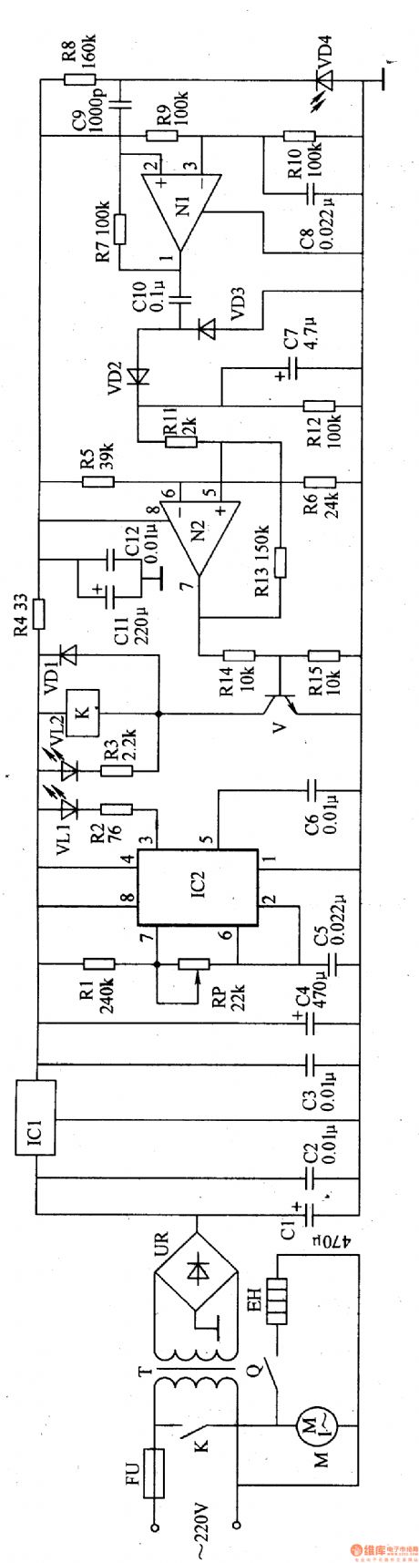
Automatic hand dryer 3
Published:2011/5/16 21:46:00 Author:Nicole | Keyword: hand dryer

The circuit work theory
This automatic hand dryer circuit is composed of power supply, optical control circuit and control implement circuit, the circuit is shown in the figure 9-126.
The power supply circuit is made of depressurization capacitor C1, bleeder resistor R1, voltage stabilizing diode VS, rectifier diode UD1 and filter capacitor C2.
The optical control circuit is made of indicator light HL, light dependent resistor RG, resistor, capacitors C3, C4, potentiometer RP and time base integrated circuit IC.
The control implement circuit consists of relay K, diode VD2, heating wire EH and fan motor M.
(View)
View full Circuit Diagram | Comments | Reading(3731)
ISO100 optocoupler linear isolated amplifier circuit diagram
Published:2011/5/17 2:51:00 Author:Ecco | Keyword: optocoupler , linear , isolated amplifier
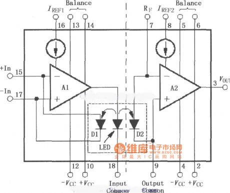
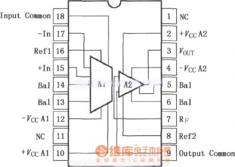
ISO100 is the optocoupler isolation amplifier. It uses LED to produce coupling light, and the negative feedback of coupling light is added to the input end, while the measures on output end of forward transmission can achieve a high precision, linear and long temperature stability. The fine matching coupler and amplifier laser correction ensure the integration of its excellent adjustment performance and low offset error. ISO100 can be used as a current - voltage converter, there is 750V (2500V test voltage) voltage between the input and output ends, it effectively disconnects the the contact of the public current between input and output ends with ultra-low leakage current, the maximum leakage current is 0.3μA when the current is at 240V, 60Hz.
(View)
View full Circuit Diagram | Comments | Reading(2589)
Infrared automatic hand washing device 1
Published:2011/5/17 0:59:00 Author:Nicole | Keyword: hand washing device
The circuit work theory
This infrared automatic hand washing device circuit is composed of power supply, infrared detection control circuit and control implement circuit, the circuit is shown in the figure 9-119.
The power supply circuit is made of capacitor C1, C2, resistor R1, voltage stabilizing diode VS and rectifier diode VD.
The infrared detection control circuit consists of resistors R2-R7, capacitors C3-C5, diode VD2, transistors V1, V2, pyroelectric infrared sensor integrated circuit IC1 and time base integrated circuit IC2.
The control implement circuit is composed of optical coupler VLC and electromagnetic valve YV.
(View)
View full Circuit Diagram | Comments | Reading(2335)
MAX4265 ~ MAX4270 voltage feedback op amp circuit diagram
Published:2011/5/17 2:24:00 Author:Ecco | Keyword: voltage feedback , op amp
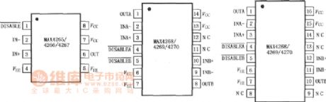
MAX4265 ~ MAX4270 voltage feedback operational amplifier has a low distortion, it will remain extremely low distortion in the context of the entire bandwidth of driving 100Ω load. They provide excellent spurious free dynamic range (SFDR), when the frequency is lower than 5MHz-90dBc or better; the 100MHz is-60dBc. Single power supply voltage is +4.5 ~ +8.0 V, dual power supply voltage is ± 2.25 ~ ± 4.0V. These features of MAX4265 ~ MAX4270 make them be ideal for high-performance communications and signal processing applications, because these applications require very low distortion and wide bandwidth.
(View)
View full Circuit Diagram | Comments | Reading(657)
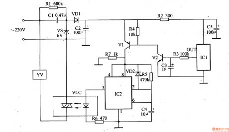
Automatic hand dryer 5
Published:2011/5/16 21:12:00 Author:Nicole | Keyword: hand dryer
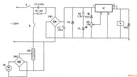
The circuit work theory
This automatic hand dryer circuit is composed of power supply, infrared control circuit and hot air generation circuit, the circuit is shown in the figure 9-128.
The power supply is made of power supply switch S, depressurization capacitor C1, resistor R1, bridge rectifier UR1, filter capacitor C2 and voltage stabilizing diode VS.
The infrared control circuit consists of current limiting resistor R2, infrared LED VL, infrared photosensitive diode VD1, potentiometer RP, electronic switch integrated circuit IC, diode VD2 and relay K.
The hot air generation circuit is composed of K often open contact, heater EH, bridge rectifier UR2 and fan motor M.
(View)
View full Circuit Diagram | Comments | Reading(3121)
Lavatory automatic flusher 1
Published:2011/5/17 1:14:00 Author:Nicole | Keyword: Lavatory, flusher
The circuit work theory
This lavatory automatic flusher circuit is composed of power supply circuit, infrared transmitting circuit, infrared receiving circuit, decoder circuit, delay control circuit, LED indication circuit and control implement circuit, the circuit is shown in the figure 9-129.
The power supply circuit is made of fuse FU, capacitors C1, C2, resistor R1, voltage stabilizing diode VS and rectifier diode VD.
The infrared transmitting circuit consists of time base integrated circuit IC1, resistors R2, R3, potentiometer RP1, capacitor C3 and infrared LED VL1.
(View)
View full Circuit Diagram | Comments | Reading(745)
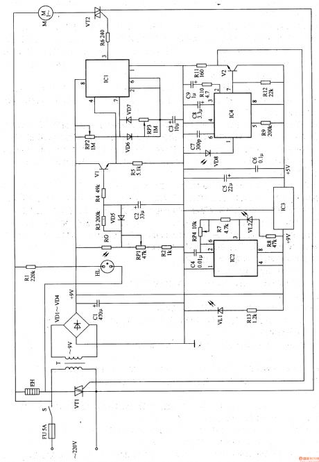
Motor electronic governor controller 1
Published:2011/5/17 1:45:00 Author:Nicole | Keyword: motor, electronic governor, controller
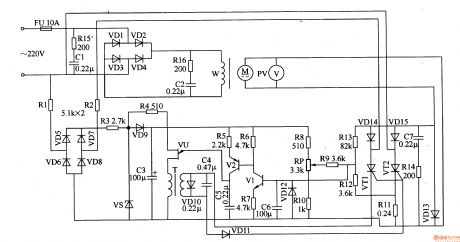
The circuit work theory
This motor electronic governor controller circuit is composed of power supply circuit, excitation circuit, trigger circuit and speed governing control circuit, the circuit is shown in the figure 8-58.
The power supply circuit is made of fuse FU, resistors R1-R3, rectifier diode VD5-VD9, voltage stabilizing diode VS and filter capacitor C3.
The excitation circuit consists of resistors Rl5, Rl6, capacitors C1, C2 and diodes Dl-D4.
The trigger control circuit is composed of pulse transformer T, unijunction transistor VU, transistors V1, V2, diode VDlO-VDl2, capacitors C4-C6 and resistors R4-R7.
(View)
View full Circuit Diagram | Comments | Reading(2680)
| Pages:1866/2234 At 2018611862186318641865186618671868186918701871187218731874187518761877187818791880Under 20 |
Circuit Categories
power supply circuit
Amplifier Circuit
Basic Circuit
LED and Light Circuit
Sensor Circuit
Signal Processing
Electrical Equipment Circuit
Control Circuit
Remote Control Circuit
A/D-D/A Converter Circuit
Audio Circuit
Measuring and Test Circuit
Communication Circuit
Computer-Related Circuit
555 Circuit
Automotive Circuit
Repairing Circuit