
Circuit Diagram
Index 1876
IX0689 switch power supply circuit
Published:2011/5/15 5:10:00 Author:John | Keyword: switch
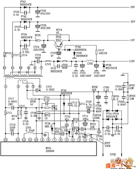
IX0689 switch power supply circuit is given in the following.
(View)
View full Circuit Diagram | Comments | Reading(616)
Light-emitting time automatic control circuit
Published:2011/5/15 5:08:00 Author:John
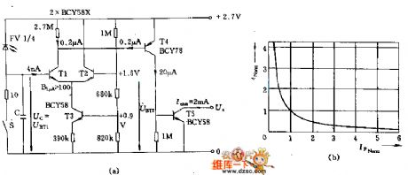
The intensity of the light-emitting time automatic control is relative to the signals of time. And this circuit can work under a very small illumination (such as 250mLX). Photodiode adopts FV1 / 4-type elements with an area of F ≈ 9mm2. The operating voltage of 2.7V can be powered in series by two batteries. When it is not connected, the absorbed current is 2μA. The differential amplifiers T1 and T2 both have a high sensitivity and the current of emitter is 1μA. Afterwards, the BCY58 continues to amplify. (View)
View full Circuit Diagram | Comments | Reading(575)
High-speed voltage follower circuit
Published:2011/5/15 3:37:00 Author:John | Keyword: High-speed voltage follower
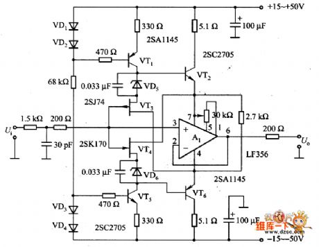
The figure is a high-speed voltage follower circuit. The circuit is constituted by the VT3 and VT4. Al is the voltage follower circuit, which is constituted by the pin 7 of A1 and pin 4 of VT2 and VT6. Pin 7 of and pin 4 are just level shifting positions of the input signal voltage. Therefore, when the input signal is large, the power supply voltage on all-aspect of A1 and output end remains constant about 5V. As signal current through phase compensation capacitor from the Al-chip surges, the conversion rate has been greatly improved and high frequency distortion has been significantly reduced.
(View)
View full Circuit Diagram | Comments | Reading(1212)
The features and circuit of Santana 2000GSi ABS system
Published:2011/5/13 19:54:00 Author:Borg | Keyword: Santana, ABS system
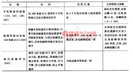
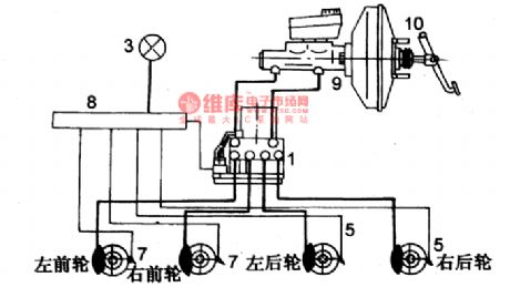
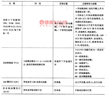
Santana 200GSi is installed with MK-20I ABS system produced by lTT Corp., the USA,which consists of controller(hydraulic controller, ABS computer ECU, hydraulic pump ), 4 wheel sensors, ABS fault warning indicators and brake warning lamp. The functions, installation position, main features and parameters are as shown in Figure 5.
The ABS and installation positions of Santana 2000 are as shown in Figure 7.
The ABS wiring circuit of Shanghai Santana 2000GSi is as shown in Figure 7 and Figure 8. (View)
View full Circuit Diagram | Comments | Reading(849)
RS232-TTl-RS485 switching interface circuit
Published:2011/5/15 2:53:00 Author:John
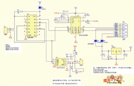
RS232-TTl-RS485 switching interface circuit is given in the following.
(View)
View full Circuit Diagram | Comments | Reading(9201)
MAX1626 Fan speed control circuit
Published:2011/5/15 5:23:00 Author:John | Keyword: Fan
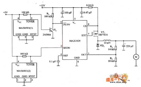
The figure is the speed control circuit of fan, which is mainly constituted by the MAX1626. This circuit reduces the noise and power consumption of the computer, the temperature controller and alarm systems. It achieves by utilizing the closure and output voltage of MDH626. The logic level voltage is added to pin 2 (3V/5V) and pin 3 (SHDN). At the same time, appropriate feedback resistor (Rl and R2) are selected to set the output voltage. In general, low output voltage U (01) (here for 8V) is determined by the sub-decision resistors R1 and R2. And the high output voltage U (02) (here for 12V) is determined by voltage on output end of the chip (pin 4).
(View)
View full Circuit Diagram | Comments | Reading(931)
Power supply over voltage detection and time delay protection circuit diagram
Published:2011/5/16 3:19:00 Author:Rebekka | Keyword: over voltage detection , time delay protection
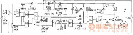
For some electrical equipments, the operating supply voltage range is strictly limited. Over-voltage or under-voltage will affect the work or even damage the equipment. The following shows a over-voltage and under voltage detection and time delay protection circuits. It can cut off the power supply when it is over-voltage or under-voltage. And it can start automatically after a period of delay. It is composed of two four-two input NAND gates CD4011. The over voltage and under-voltage detection circuit is composed of D1-D3 and RPl, RP2. D4 is trigger circuit. The relay driver circuit is composed of D7, D8 and transistor VT. The time relay restart circuit is composed of D5, D6 and R4, C5. (View)
View full Circuit Diagram | Comments | Reading(1828)
Chery QQ6 entire Automobile circuit
Published:2011/5/15 5:25:00 Author:John | Keyword: Chery QQ6
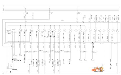
Chery QQ6 entire Automobile circuit is shown below.
(View)
View full Circuit Diagram | Comments | Reading(559)
Mine-site indicating lights circuit
Published:2011/5/15 3:23:00 Author:John | Keyword: indicator
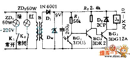
The lights installed in the mining sites are used to help drivers to notice the situation behind the car and to avoid accidents. Phototransistor is used as optical signal sensor. When the light shines on the photodiodes, the relay J picks up. A pair of normally opened contact closes. The green light starts to shine, indicating that there is no obstacle behind the car. If there is any obstacle blocking the light , the relay J does not picks up and the red light shines.
(View)
View full Circuit Diagram | Comments | Reading(540)
Hemisphere CBW series of heat wave oven circuit diagram
Published:2011/5/16 3:26:00 Author:Ecco | Keyword: Hemisphere, CBW series , heat wave oven
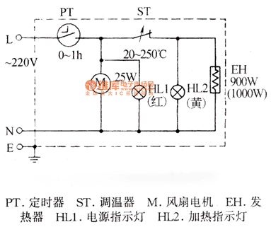
PT-timer, ST-thermostat, M-fan motor, EH-heater, HL1-power indicator light, HL2 heat indicator light
(View)
View full Circuit Diagram | Comments | Reading(1350)
CXA1191M radio circuit
Published:2011/5/15 2:30:00 Author:John | Keyword: CXA1191M radio
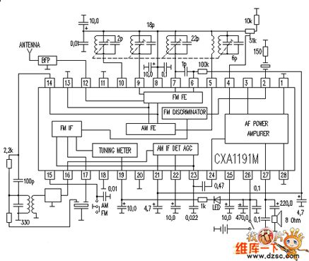
CXA1191M radio circuit is shown below.
(View)
View full Circuit Diagram | Comments | Reading(4652)
audio amplifier 2W circuit
Published:2011/5/15 3:08:00 Author:John | Keyword: audio amplifier
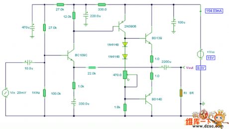
Audio amplifier 2W circuit is shown below.
(View)
View full Circuit Diagram | Comments | Reading(886)
CS8952 Ethernet network interface circuit
Published:2011/5/15 4:48:00 Author:John | Keyword: network interface
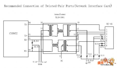
CS8952 Ethernet network interface circuit is shown below.
(View)
View full Circuit Diagram | Comments | Reading(671)
bridge amplifier circuit with a low-noise compensation circuit
Published:2011/5/15 2:02:00 Author:John | Keyword: low-noise compensation circuit, bridge amplifier
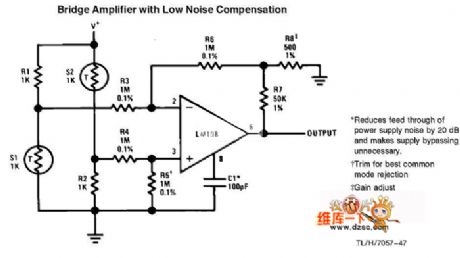
bridge amplifier circuit with a low-noise compensation circuit
(View)
View full Circuit Diagram | Comments | Reading(1112)
New TDH98072 dedicated pyroelectric infrared sensor circuit diagram
Published:2011/5/16 3:13:00 Author:Ecco | Keyword: New , dedicated , pyroelectric , infrared , sensor
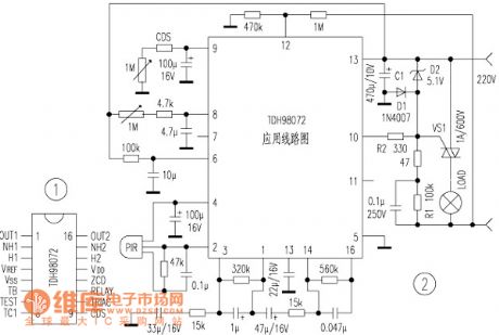
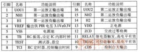
TDH98072 is a new pyroelectric infrared sensor specific devices. The output current of the circuit is high with PIR sensor input, and it can drive SCR, relay. In addition, the circuit uses CMOS process, the quiescent current is less than 1mA when it works. The control circuit composed of the circuit (such as burglar alarm, automatic lights, automatic valve) has the features of simple structure, easy adjustment, high reliability. 1. The shape and pin arrangement of TDH98072 are shown in Figure 1.
Photoresistor should select bright resistor(bright environment in the resistance) being less than 100kΩ, the dark resistance is greater than 3.3MΩ,pyroelectric infrared probe PIR can choose any small pyroelectric probes (must bring lens, such as ANM1 type), the other component parameters are shown in the figure.
(View)
View full Circuit Diagram | Comments | Reading(1595)
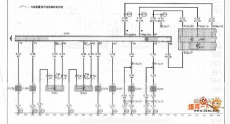
Audi A4 Car 01V Automatic Transmission,ABS and SRS control circuit
Published:2011/5/15 4:44:00 Author:John | Keyword: Automatic Transmission
View full Circuit Diagram | Comments | Reading(1597)
Internal circuit of crystal diode DDZXDDZXS
Published:2011/5/15 3:25:00 Author:John | Keyword: crystal diode DDZXDDZXS
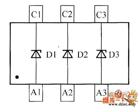
Internal circuit of crystal diode DDZXDDZXS is shown below.
(View)
View full Circuit Diagram | Comments | Reading(596)
Wireless snooping device circuit
Published:2011/5/15 3:14:00 Author:John | Keyword: Wireless snooping device
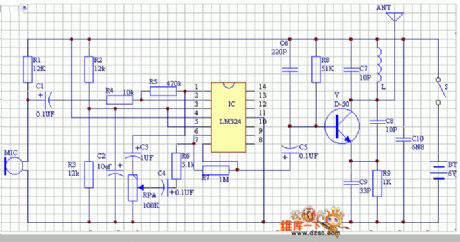
Wireless snooping device circuit is given in the following.
(View)
View full Circuit Diagram | Comments | Reading(568)
Home appliances overvoltage protector circuit diagram
Published:2011/5/15 5:55:00 Author:Rebekka | Keyword: Home appliances , overvoltage protector
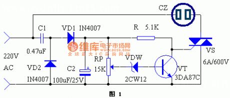
When the voltage suddenly rises because of some reason,household appliances such as the running refrigerators, washing machines, televisions, stereos, computers will face varying degrees of damage, even catch serious fire, causing great economic loss. This paper describes a simple over-voltage protection device, which provides protective effects on the appliance. When the voltage exceeds the allowable range, thepower supply will automatically cut off. Once the voltage turns to normal, the power can be automatically switched back. (View)
View full Circuit Diagram | Comments | Reading(2074)
non-inverting AC amplifier circuit
Published:2011/5/15 2:59:00 Author:John | Keyword: AC amplifier
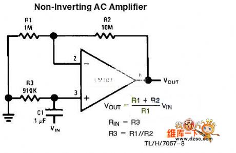
Non-inverting AC amplifier circuitis shown below.
(View)
View full Circuit Diagram | Comments | Reading(3336)
| Pages:1876/2234 At 2018611862186318641865186618671868186918701871187218731874187518761877187818791880Under 20 |
Circuit Categories
power supply circuit
Amplifier Circuit
Basic Circuit
LED and Light Circuit
Sensor Circuit
Signal Processing
Electrical Equipment Circuit
Control Circuit
Remote Control Circuit
A/D-D/A Converter Circuit
Audio Circuit
Measuring and Test Circuit
Communication Circuit
Computer-Related Circuit
555 Circuit
Automotive Circuit
Repairing Circuit