
Circuit Diagram
Index 2201
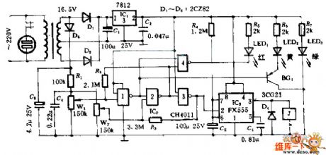
LED Holiday lights controller circuit diagram 6
Published:2011/3/30 20:37:00 Author:Ecco | Keyword: LED Holiday lights, controller
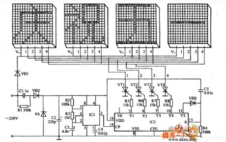
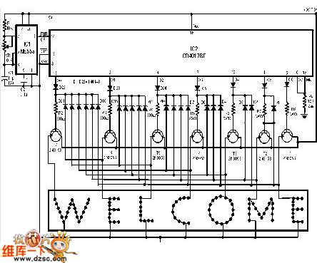
The LED holiday lights controller introduced in the example can display four sentences four words composing of many LEDs(such as celebrating May Day and long live our motherland ), and they display in time sequence to add festive atmosphere to festive night.
Circuit principle of work
This LED holiday lights controller circuit is composed of power supply circuit, pulse generator and control circuit and LED display circuit component, as shown in figure.
Power circuit is composed of voltage step-down capacitor Cl, bleeder resistors Rl, rectifier diode VDl, VD2, voltage-regulator diode VS and filter capacitor C2.
Pulse generator is composed of time-based integrated circuit ICl, resistor R2, R3 and capacitor C3, C4.
Control circuit is composed of decimal count/pulse splitter integrated circuit IC2, diodes VD3, resistors R4 - R8 and capacitor C5 and thyristor VTl-VW. (View)
View full Circuit Diagram | Comments | Reading(723)
Micro active amplifier circuit diagram
Published:2011/3/30 2:32:00 Author:Rebekka | Keyword: Micro active amplifier
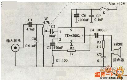
Here is the schematic diagram of the micro active amplifier circuit:
(View)
View full Circuit Diagram | Comments | Reading(711)
The balanced input amplifier circuit diagram of 600Ω microphone
Published:2011/3/29 20:10:00 Author:Ecco | Keyword: balanced input, amplifier, 600Ω microphone
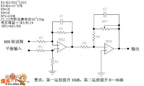
The balanced input amplifier circuit diagram of 600Ω microphone is as the chart. (View)
View full Circuit Diagram | Comments | Reading(1600)
Ratio of the unknowns circuit diagram
Published:2011/3/29 20:11:00 Author:Ecco | Keyword: Ratio of the unknowns
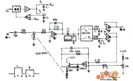
This circuit is used as the situation of two signals share the same input line, for example, two leds irradiate a single photocell alternately. To measure the ratio of two unknowns, the precision better than 1%. During the period of T1, the input signal is sampled by S2, and storaged in C2, so that to make a comparison with reference voltage, the result of which can be obtained by the amplifier network AFE, added to gain control elements CLM6000. The adjusting signal gain of closed loop is increased, and the denominator of ratio is equal to reference voltage. And the molecular corresponding to T2 multiplied by the same gain, so the output of molecular direct ratio to the needed unknow value B/A .
(View)
View full Circuit Diagram | Comments | Reading(442)
Transmitter circuit diagram
Published:2011/3/29 20:51:00 Author:Rebekka | Keyword: Transmitter
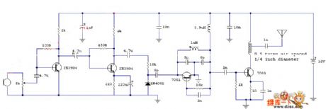
Here is the schematic diagram of the transmitter circuit:
(View)
View full Circuit Diagram | Comments | Reading(682)
The white LED drive circuit diagram composed of MAX1554
Published:2011/3/29 20:07:00 Author:Ecco | Keyword: white LED drive

According to the figure, it is a circuit diagram of white LED drive composed by the MAX1554. It is the white LED drive circuit whichis supplied by 2 to 4 section batteries, the brightness's maximum will keep constant. The Rl is a current examination resistance, its resistivity is 27 Ω, therefore LED current is about 10 mA. For enlarging current, the L1 needs to adopt a saturated density of magnetic flux higher inductance.
(View)
View full Circuit Diagram | Comments | Reading(757)
500W push-pull DCDC converter circuit diagram
Published:2011/3/29 20:53:00 Author:Rebekka | Keyword: 500W push-pull , DCDC converter
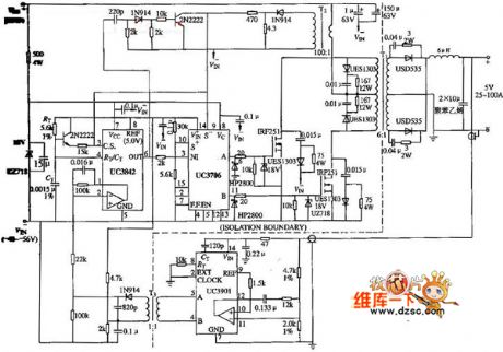
Here is the schematic diagram of the 500W push-pull DCDC converter circuit:
(View)
View full Circuit Diagram | Comments | Reading(3437)
USB camera circuit diagram
Published:2011/3/30 2:22:00 Author:Rebekka | Keyword: USB camera
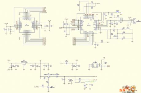
Here is the schematic diagram of the USB camera circuit: (View)
View full Circuit Diagram | Comments | Reading(5875)
USB to 232 serial port circuit diagram
Published:2011/3/30 2:23:00 Author:Rebekka | Keyword: usb to 232 serial port
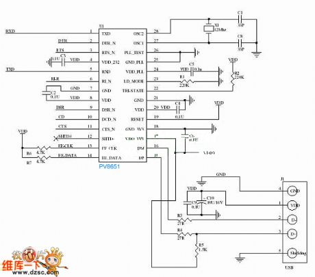
Here is the schematic diagram of the USB to 232 serial portcircuit:
(View)
View full Circuit Diagram | Comments | Reading(1133)
Cell phone battery constant-current charger circuit diagram
Published:2011/3/29 20:05:00 Author:Ecco | Keyword: Cell phone battery , constant-current, charger
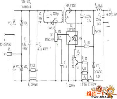
Cell phone battery constant-current charger circuit diagram is as below:
(View)
View full Circuit Diagram | Comments | Reading(3260)
Automatic instructions protection circuit diagram
Published:2011/3/29 20:05:00 Author:Ecco | Keyword: Automatic instructions protection
When the electric supply in the circuitry is higher than the limit set by W1, LED 2 will be lit, door 2 will be closed, output 1, J pulled in, closed contact is disconnected. That could realize the purpose of temporary protection to interruption. When the electric supply is lower than the limit, door 4 opened, LED 1 lit, the output of door 3 is 0 , J pulled in. That also could realize the purpose of temporary protection to interruption. (View)
View full Circuit Diagram | Comments | Reading(683)
The circuit diagram of light signal receiving
Published:2011/3/29 20:03:00 Author:Ecco | Keyword: light signal receiving
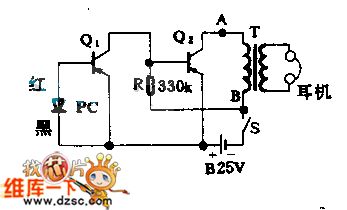
This circuitry adopts the photoelectric cell IR-B2 M type to receive semaphore. Optics semaphore can be optical light or infrared light, and it takes the LED or semiconductor laser machine as light source, and the municipally frequency should be 0.5~2.0 KHZ. When the photocell is irradiated, it can produce quadrature voltage and be amplifiered by Q1, Q2, then the voltage will pass a output transformer which mutually matches with earphone impedance. Consequently, we can use earphone to hear the sound clearly.
(View)
View full Circuit Diagram | Comments | Reading(789)
CD4541 cadmium nickel storage cell recharger circuit diagram
Published:2011/3/29 20:01:00 Author:Ecco | Keyword: cadmium nickel storage cell , recharger

CD4541 cadmium nickel storage cell recharger circuit diagram is as below:
(View)
View full Circuit Diagram | Comments | Reading(1414)
The elementary diagram of electronic biological wave physical circuit
Published:2011/3/29 20:01:00 Author:Ecco | Keyword: electronic biological wave, physical circuit
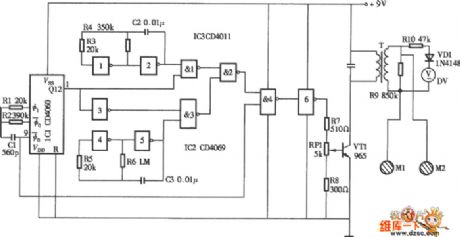
The elementary diagram of electronic biological wave physical circuit is as below:
(View)
View full Circuit Diagram | Comments | Reading(1862)
LED circuit diagram
Published:2011/3/28 1:15:00 Author:Ecco | Keyword: LED
View full Circuit Diagram | Comments | Reading(778)
The internal circuit diagram of crystal diode DM1500LFD5
Published:2011/3/29 2:52:00 Author:Ecco | Keyword: crystal diode
The internal circuit diagram of crystal diode DM1500LFD5 is as below:
(View)
View full Circuit Diagram | Comments | Reading(449)
The internal circuit diagram of crystal diode HZM27FA
Published:2011/3/29 2:51:00 Author:Ecco | Keyword: crystal diode

The internal circuit diagram of crystal diode HZM27FA is as below:
(View)
View full Circuit Diagram | Comments | Reading(529)
The internal circuit diagram of crystal diode HM5.6FA
Published:2011/3/29 2:49:00 Author:Ecco | Keyword: crystal diode
The internal circuit diagram of crystal diode HM5.6FA is as below:
(View)
View full Circuit Diagram | Comments | Reading(466)
Cadillac sunshading board circuit diagram
Published:2011/3/29 2:48:00 Author:Ecco | Keyword: sunshading board
View full Circuit Diagram | Comments | Reading(547)
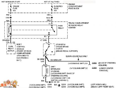
Cadillac gear interlock circuit diagram
Published:2011/3/29 2:43:00 Author:Ecco | Keyword: gear interlock
View full Circuit Diagram | Comments | Reading(596)
| Pages:2201/2234 At 2022012202220322042205220622072208220922102211221222132214221522162217221822192220Under 20 |
Circuit Categories
power supply circuit
Amplifier Circuit
Basic Circuit
LED and Light Circuit
Sensor Circuit
Signal Processing
Electrical Equipment Circuit
Control Circuit
Remote Control Circuit
A/D-D/A Converter Circuit
Audio Circuit
Measuring and Test Circuit
Communication Circuit
Computer-Related Circuit
555 Circuit
Automotive Circuit
Repairing Circuit