
Circuit Diagram
Index 2211
LED display circuit diagram driving by 74HC164
Published:2011/3/28 22:10:00 Author:Ecco | Keyword: LED display
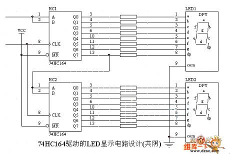
LED display circuit diagram driving by 74HC164 is as below:
(View)
View full Circuit Diagram | Comments | Reading(7486)
15V、1A Collector output regulators power supply circuit diagram
Published:2011/3/21 1:46:00 Author:Rebrecca | Keyword: Collector output, regulators power supply
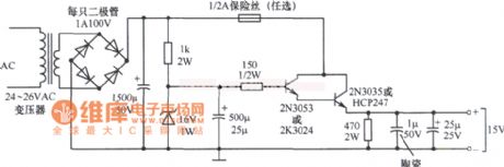
15V、1A Collector output regulators power supply circuit diagram is shown as below.
(View)
View full Circuit Diagram | Comments | Reading(594)
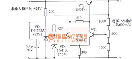
15V、600mA Regulators power supply circuit diagram
Published:2011/3/21 1:46:00 Author:Rebrecca | Keyword: Regulators, power supply
15V、600mA Regulators power supply circuit diagram is shown as below.
(View)
View full Circuit Diagram | Comments | Reading(885)
15V Parallel regulators power supply circuit diagram
Published:2011/3/21 1:46:00 Author:Rebrecca | Keyword: Parallel regulators , power supply
15V Parallel regulators power supply circuit diagram is shown as below.
(View)
View full Circuit Diagram | Comments | Reading(602)
13V、2A simple steady voltage power supply circuit diagram
Published:2011/3/21 1:46:00 Author:Rebrecca | Keyword: simple steady voltage , power supply
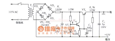
13V、2A simple steady voltage power supply circuit diagram is shown as below.
(View)
View full Circuit Diagram | Comments | Reading(1150)
-9~-l4.5v Collector output regulators power supply circuit diagram
Published:2011/3/21 1:46:00 Author:Rebrecca | Keyword: Collector output , regulators power supply
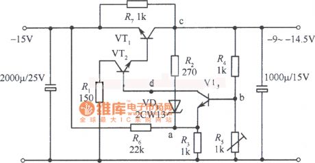
-9~-l4.5v Collector output regulators power supply circuit diagram is shown as below.
(View)
View full Circuit Diagram | Comments | Reading(677)
Simple 15V regulators Power Supply Circuit Diagram
Published:2011/3/21 1:46:00 Author:Rebrecca | Keyword: regulators Power Supply
Simple 15V regulators Power Supply Circuit Diagram is shown as below.
(View)
View full Circuit Diagram | Comments | Reading(566)
Low level capacitor measuring circuit diagram
Published:2011/3/22 1:00:00 Author:Ecco | Keyword: Low level capacitor
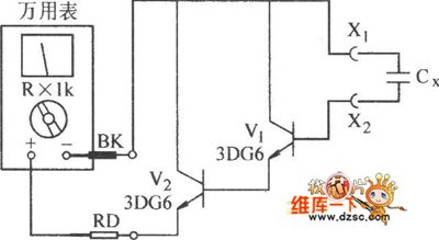
Low level capacitor measuring circuit diagram is as below:
(View)
View full Circuit Diagram | Comments | Reading(738)
The inside circuit diagram of crystal triode PEMD12
Published:2011/3/22 0:50:00 Author:Ecco | Keyword: crystal triode
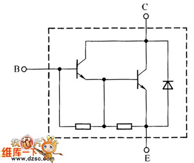
The inside circuit diagram of crystal triode PEMD12 is as below:
(View)
View full Circuit Diagram | Comments | Reading(470)
Solid laser range finder receive circuit diagram
Published:2011/3/24 20:45:00 Author:Ecco | Keyword: Solid laser , range finder
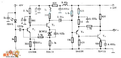
This circuitry zooms in magnification of 1200000 times, the bandwidth is 0.5~14 Mhzs, the input impedance is 700 Ω, the output impedance is 35 Ω(to measure in the 5 MHZ), the output level of noise is 0.6~0.8 V.
In the chart, T1 and T2 are direct coupling amplifiers, and be current negative feedback in parallel connection. The promotion of T2's emitter level by steady diode 2CM11 to assure the level installing relationship between T1 and T2.
T3 and T4 is a pair of direct-coupling feedback, belonging to voltage current negative feedback in series connection. It can increase the transmitting coefficient of low load impedance by derating output impedance.
(View)
View full Circuit Diagram | Comments | Reading(4993)
0--25V、0~10A constant voltage/constant current power supply circuit
Published:2011/3/21 1:45:00 Author:Rebrecca | Keyword: constant voltage, constant current
0--25V、0~10A constant voltage/constant current power supply circuitis shown as below.
(View)
View full Circuit Diagram | Comments | Reading(4398)
Dual Output Regulators Power Supply Circuit Diagram
Published:2011/3/21 1:45:00 Author:Rebrecca | Keyword: Dual Output Regulators, Power Supply
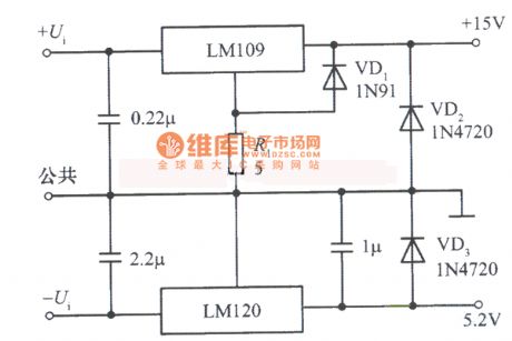
Dual Output Regulators Power Supply Circuit Diagram is shown as below.
(View)
View full Circuit Diagram | Comments | Reading(668)
Multiple Output Switch Regulators Voltage Power Supply Circuit Diagram
Published:2011/3/21 1:45:00 Author:Rebrecca | Keyword: Multiple Output Switch, Regulators Voltage , Power Supply
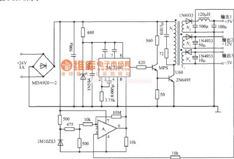
Multiple Output Switch Regulators Voltage Power Supply Circuit Diagram is shown as below.
(View)
View full Circuit Diagram | Comments | Reading(2200)
Fan speed control circuit with remote control
Published:2011/3/21 1:38:00 Author:Allen | Keyword: Fan speed control, remote control

View full Circuit Diagram | Comments | Reading(1865)
Series motor full-wave control circuit
Published:2011/3/21 1:38:00 Author:Allen | Keyword: Series motor, full-wave control


The circuit adopts transistor phase-shift trigger and one-way thyristor to control the full-wave voltage of series motor circuit, so it can control motor speed at a wide range. Resistor R5 in series on one-way thyristor main circuit constitutes negative feedback, which can stabilize the speed. The values of R5 is 0.1-1 Ω. Br diode rectifier bridge can convert AC to DC.
(View)
View full Circuit Diagram | Comments | Reading(992)
5V、1A Switch fixed power supply circuit diagram
Published:2011/3/21 1:45:00 Author:Rebrecca | Keyword: fixed power supply
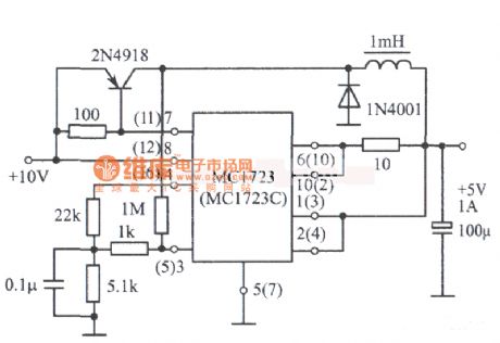
5V、1A Switch fixed power supply circuit diagram is shown as below.
(View)
View full Circuit Diagram | Comments | Reading(2424)
PWM speed control circuit of electric bicycles
Published:2011/3/21 1:37:00 Author:Allen | Keyword: PWM, electric bicycle

View full Circuit Diagram | Comments | Reading(3481)
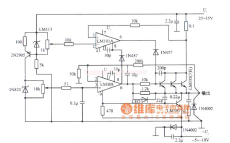
Precision Double Tracking Regulators Voltage Power Supply Circuit Diagram
Published:2011/3/21 1:45:00 Author:Rebrecca | Keyword: Precision Double Tracking, Regulators Voltage
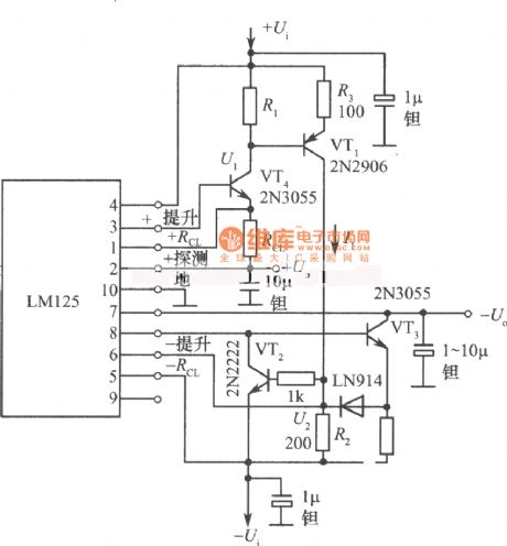
Precision Double Tracking Regulators Voltage Power Supply Circuit Diagram is shown as below.
(View)
View full Circuit Diagram | Comments | Reading(750)
TTL Logic level controled double tracking regulators voltage power supply circuit diagram
Published:2011/3/21 1:45:00 Author:Rebrecca | Keyword: TTL Logic level, double tracking, regulators voltage
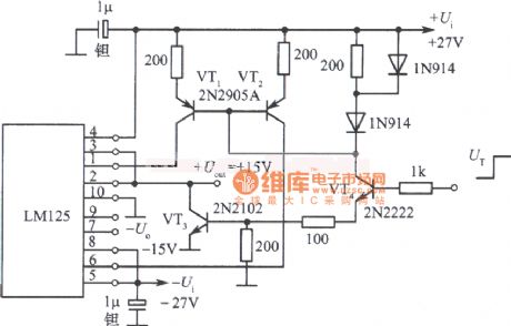
TTL Logic level controled double tracking regulators voltage power supply circuit diagram is shown as below.
(View)
View full Circuit Diagram | Comments | Reading(807)
Electric blanket automatic protection constant temperature circuit
Published:2011/3/21 1:33:00 Author:Allen | Keyword: Electric blanket, automatic protection, constant temperature


Currently, many electric blankets temperature control use manually switch, which adopts a fast and a slow thermal step for temperature control, so that the internal temperature of electric blanket is difficult to control at a constant temperature to work, as a result, a lot of trouble is brought. This paper introduces a electric blanket automatic control circuit, which can not only work at a predetermined temperature, but also play a role in self-locking power and over voltage protection.
The circuit principle is shown in figure 1. It consists of power-failing and self-locking circuit, overvoltage protection and automatic constant temperature control circuit. When the button switch S2 is pressed, 220V AC is used for relay J after passing capacitor C2 step-down voltage, V6 and V7 regulator rectifier and C3 filter, then J powered on and normally open contact J1 connected make the circuit self-locking. At this time, it can maintain power to the electric blanket and the relay J, even if the button switch S2 releases. When encountered power outage in the use of electric blanket, the relay J powers off and release, normally open contact J1 powers off, so the electric blanket does not work. When the power grid restores power supply, the relay and electric blankets can not automatically power on, only press s2 again, and the relay J pull, so electric blankets will be re-energized work.
Rt is a positive temperature coefficient thermistor. Its internal resistance varies with the high and low temperature, that is, at high temperature, the internal resistance increases, and vice versa. The electric blankets constant temperature control circuit is composed of the rectifier diode V2 ~ V5, one-way thyristor SCR, two-way trigger diode V1, positive temperature coefficient thermistor Rt, capacitor C1, RP potentiometer. The control process is: AC turns into DC by V2 ~ V5 bridge rectifier, charge to C1 by RP and Rt, when the voltage of C1 reaches a certain value, the bi-directional trigger diode conducts and breakdowns in a discharge state. At this point, one-way thyristor SCR is triggered and powered on, which make the blanket work. When internal temperature in the electric blanket rises a certain value, the internal thermistor resistance Rt is great, but the voltage of C1 is small, which can not make V1 breakdown, so the SCR turn-off. Relatively, the electric blanket is off and does not work, it is in a cooling state. When the electric blanket temperature drops to a certain value, then repeat the control process, so keep the cycle, and make the blanket temperature at a constant value. If the grid appears over voltage, varistor MY internally (ie in-state) is short circuit, and quickly burn out fuse RD, and thus play a role in over-voltage automatic protection. Figure 2 is the device's printed circuit board assembly drawing.
(View)
View full Circuit Diagram | Comments | Reading(4151)
| Pages:2211/2234 At 2022012202220322042205220622072208220922102211221222132214221522162217221822192220Under 20 |
Circuit Categories
power supply circuit
Amplifier Circuit
Basic Circuit
LED and Light Circuit
Sensor Circuit
Signal Processing
Electrical Equipment Circuit
Control Circuit
Remote Control Circuit
A/D-D/A Converter Circuit
Audio Circuit
Measuring and Test Circuit
Communication Circuit
Computer-Related Circuit
555 Circuit
Automotive Circuit
Repairing Circuit