
Circuit Diagram
Index 2215
Switching integrated voltage regulator with 3A output current circuit
Published:2011/3/25 2:07:00 Author:Joan | Keyword: Switching integrated voltage regulator , 3A output current

View full Circuit Diagram | Comments | Reading(510)
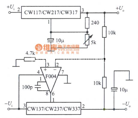
Positive and negative output voltage tracking integrated voltage regulator circuit 2
Published:2011/3/25 1:17:00 Author:Joan | Keyword: Positive and negative output voltage , tracking integrated voltage regulator
View full Circuit Diagram | Comments | Reading(690)
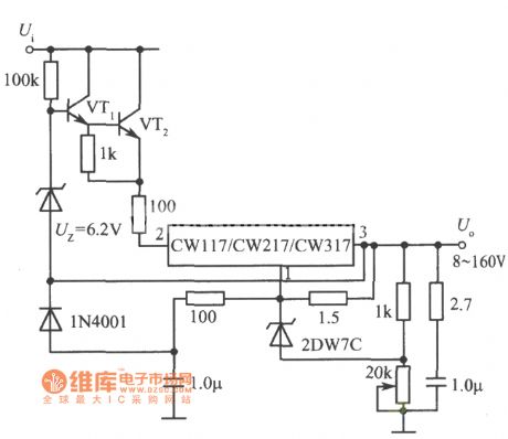
8 ~ 160V adjustable integrated voltage regulator circuit
Published:2011/3/25 1:14:00 Author:Joan | Keyword: 8 ~ 160V , adjustable integrated voltage regulator
View full Circuit Diagram | Comments | Reading(680)
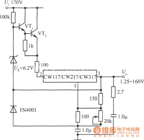
1.25 ~ 160V adjustable integrated voltage regulator circuit
Published:2011/3/25 1:13:00 Author:Joan | Keyword: 1.25 ~ 160V , adjustable integrated voltage regulator
View full Circuit Diagram | Comments | Reading(735)
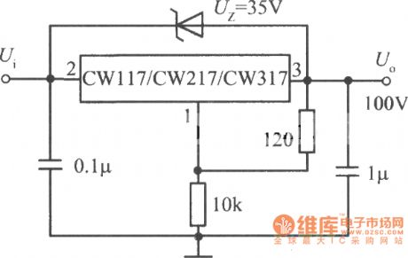
High output voltage integrated voltage regulator circuit
Published:2011/3/25 1:12:00 Author:Joan | Keyword: High output voltage , integrated voltage regulator
View full Circuit Diagram | Comments | Reading(536)
High stability integrated voltage regulator circuit
Published:2011/3/25 0:57:00 Author:Joan | Keyword: High stability , integrated voltage regulator
View full Circuit Diagram | Comments | Reading(617)
0 ~ 30V continuously adjustable integrated voltage regulator circuit
Published:2011/3/25 0:53:00 Author:Joan | Keyword: 0 ~ 30V , adjustable integrated voltage regulator
View full Circuit Diagram | Comments | Reading(691)
CR3240 printer power supply circuit
Published:2011/3/25 0:52:00 Author:Joan | Keyword: printer power supply
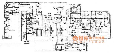
Above is CR3240 printer power supply circuit. (View)
View full Circuit Diagram | Comments | Reading(2470)
Panasonic KX-P1121 printer power supply circuit
Published:2011/3/25 0:49:00 Author:Joan | Keyword: Panasonic , printer power supply
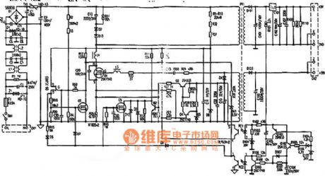
Above isPanasonic KX-P1121 printer power supply circuit. (View)
View full Circuit Diagram | Comments | Reading(1717)
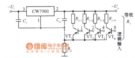
Digital control integrated voltage regulator circuit
Published:2011/3/25 0:43:00 Author:Joan | Keyword: Digital control , integrated voltage regulator
View full Circuit Diagram | Comments | Reading(638)
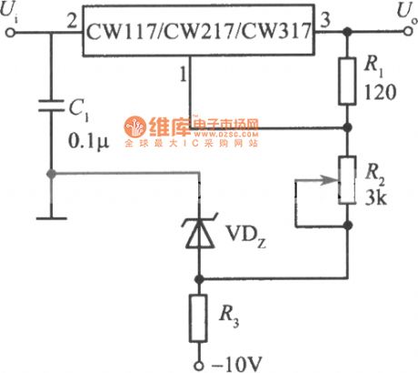
High precision and high stability +10 V integrated voltage regulator circuit
Published:2011/3/24 22:54:00 Author:Joan | Keyword: High precision and high stability , +10 V integrated voltage regulator
View full Circuit Diagram | Comments | Reading(649)
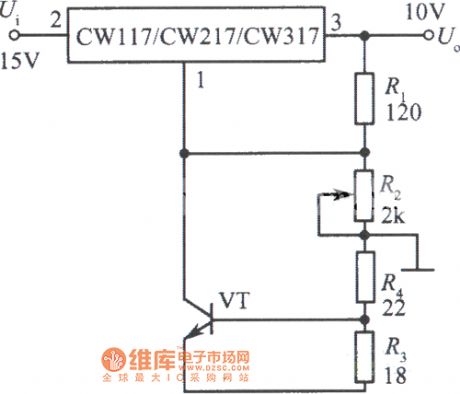
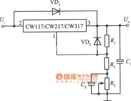
Adjustable output integrated voltage regulator with temperature compensation circuit
Published:2011/3/24 22:53:00 Author:Joan | Keyword: Adjustable output , integrated voltage regulator , temperature compensation
View full Circuit Diagram | Comments | Reading(729)
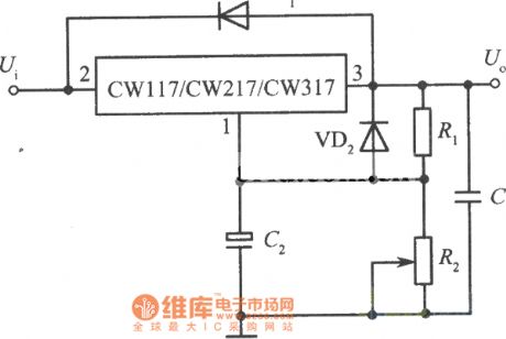
Standard adjustable integrated voltage regulator circuit
Published:2011/3/24 22:43:00 Author:Joan | Keyword: adjustable integrated voltage regulator
View full Circuit Diagram | Comments | Reading(600)
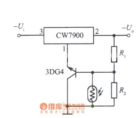
Light control integrated voltage regulator (the output voltage decreases when light on) circuit diagram
Published:2011/3/24 22:34:00 Author:Joan | Keyword: Light control , integrated voltage regulator
View full Circuit Diagram | Comments | Reading(573)
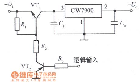
Remote shutdown style integrated voltage regulator circuit
Published:2011/3/24 22:33:00 Author:Joan | Keyword: Remote shutdown style , integrated voltage regulator
View full Circuit Diagram | Comments | Reading(768)
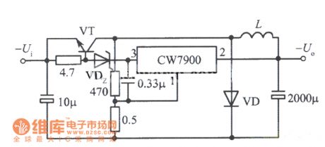
Self-excitation switching integrated voltage regulator circuit
Published:2011/3/24 22:20:00 Author:Joan | Keyword: Self-excitation , switching integrated voltage regulator
View full Circuit Diagram | Comments | Reading(602)
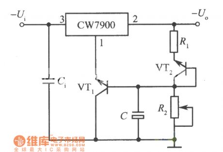
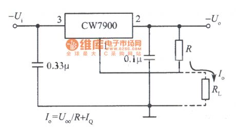
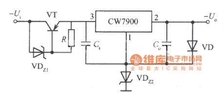
Constant current source circuit constituted of CW7900
Published:2011/3/24 22:19:00 Author:Joan | Keyword: Constant current source
View full Circuit Diagram | Comments | Reading(544)
High input - high output voltage integrated voltage regulator circuit 4
Published:2011/3/24 22:16:00 Author:Joan | Keyword: High input - high output voltage , integrated voltage regulator
View full Circuit Diagram | Comments | Reading(775)
Tire pressure gauge circuit diagram
Published:2011/3/20 22:51:00 Author:Ecco | Keyword: Tire pressure gauge
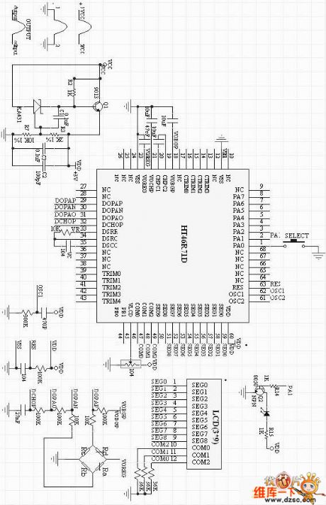
Tire pressure gauge circuit diagram is as below:
(View)
View full Circuit Diagram | Comments | Reading(1374)
The overpowering protective circuit diagram with the direct current and current measuring system MAX4211
Published:2011/3/22 21:14:00 Author:Ecco | Keyword: The overpowering protective circuit, direct current, current measuring system
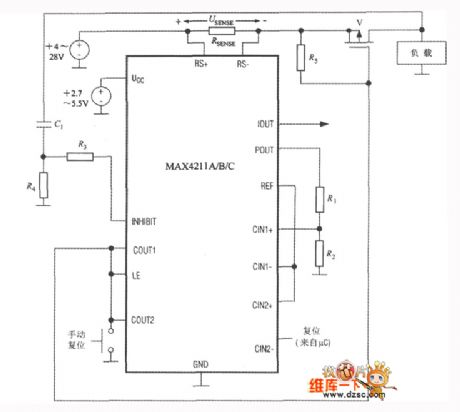
The overpowering protective circuit with MAX4211 is as below. The working principle is that the protective circuit will cut off the load current when checking out the overpowering error. The circuit can avoid the batteries from the damage of overpower of short circuit. Once it check out the overpowering error, the circuit will cut off P channel MOSFET(V) until pressing the reseting button. Simultaneously, the input power will make LE pin be in low level, and the output 1 of comparator 1 won't be locked, and the protective circuit will reset. When the characteristic of load changing, the load may produce surging current and higher voltage on POUT to cause malfunction. To avoid the circumstance, the circuit could connect a RC network(R4 and C1), and it can provide high level to INHIBIT port of comparator 1. In the term, the comparator 1 wil stop working, and the time of pause is decided by the formula that showing as below: t=R4C1ln(△U/0.6)。 In the formula, △U is variance of load voltage. The RC net will not produce an effect on the protection of long time overpowering circuit. R3 is resistance of the current limiter in 10kΩ. Follow the above-mentioned circuitry, it can be used as measuring the error of current, the exact method is connecting the resistance divider R1~R2 to IOUT port.
(View)
View full Circuit Diagram | Comments | Reading(672)
| Pages:2215/2234 At 2022012202220322042205220622072208220922102211221222132214221522162217221822192220Under 20 |
Circuit Categories
power supply circuit
Amplifier Circuit
Basic Circuit
LED and Light Circuit
Sensor Circuit
Signal Processing
Electrical Equipment Circuit
Control Circuit
Remote Control Circuit
A/D-D/A Converter Circuit
Audio Circuit
Measuring and Test Circuit
Communication Circuit
Computer-Related Circuit
555 Circuit
Automotive Circuit
Repairing Circuit