
Circuit Diagram
Index 2204
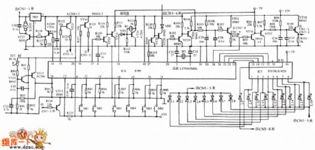
The recorder to microcomputer viewing shift circuit diagram
Published:2011/3/24 2:10:00 Author:Ecco | Keyword: recorder, microcomputer viewing
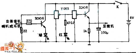
In the circuitry, the input signal from the speaker or earphone jack of recorder, and get to microcomputer.
The green light-emitted diode indicates semaphore of electrical level, red light-emitted diode indicate working state. To regulate the volume knob, click a bright light-emitted diode, then mean to input amplitude alreadyreaches 2.5 V, simultaneously, the antijamming capability is stronger. Input signal throughs two stage inverter TTL and emitter, and follows machine transfer into micro machine at the same time. (View)
View full Circuit Diagram | Comments | Reading(504)
The internal circuit diagram of crystal diode STTH16003TV
Published:2011/3/24 1:07:00 Author:Ecco | Keyword: crystal diode
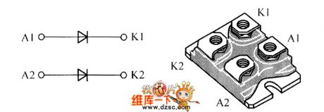
The internal circuit diagram of crystal diode STTH16003TV is as below:
(View)
View full Circuit Diagram | Comments | Reading(463)
UPS-500W Circuit diagram
Published:2011/3/24 2:12:00 Author:Ecco
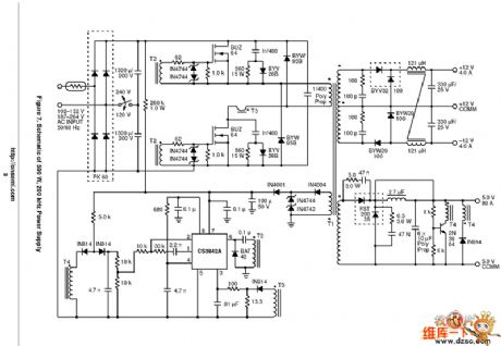
UPS-500W Circuit diagram is as below:
(View)
View full Circuit Diagram | Comments | Reading(7175)
The internal circuit diagram of crystal diode STTH2003TV
Published:2011/3/24 1:21:00 Author:Ecco | Keyword: crystal diode

The internal circuit diagram of crystal diode STTH2003TV is as below:
(View)
View full Circuit Diagram | Comments | Reading(602)
Triode constant-current supply circuit diagram
Published:2011/3/23 1:24:00 Author:Ecco | Keyword: Triode, constant-current supply
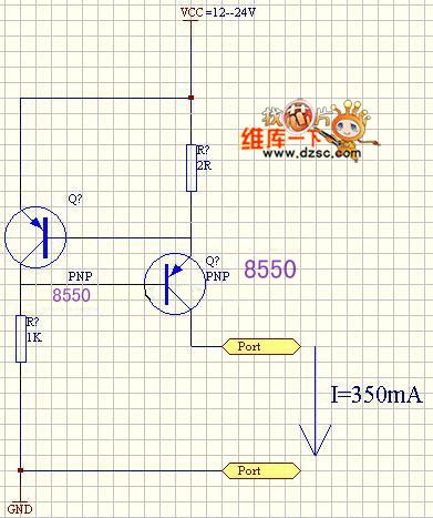
Triode constant-current supply circuit diagram is as below:
(View)
View full Circuit Diagram | Comments | Reading(895)
Induction cooker schematic circuit diagram
Published:2011/3/23 1:40:00 Author:Ecco | Keyword: Induction cooker
View full Circuit Diagram | Comments | Reading(7354)
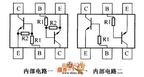
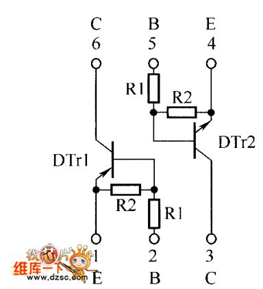
The inside circuit diagram of crystal triode DCX114YH、DCX123JH、DCX124EH、DCX144EH
Published:2011/3/24 1:04:00 Author:Ecco | Keyword: crystal triode
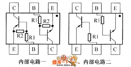
The inside circuit diagram of crystal triode DCX114YH、DCX123JH、DCX124EH、DCX144EH is as below:
(View)
View full Circuit Diagram | Comments | Reading(433)
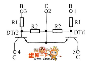
The inside circuit diagram of crystal triode DDA114EH、DDA114TH、DDA114YH、DDA123JH
Published:2011/3/24 1:04:00 Author:Ecco | Keyword: crystal triode
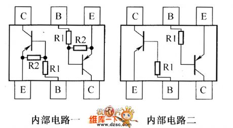
The inside circuit diagram of crystal triode DDA114EH、DDA114TH、DDA114YH、DDA123JH is as below:
(View)
View full Circuit Diagram | Comments | Reading(420)
The inside circuit diagram of crystal triode DDA124EH、DDA143EH、DDA143TH、DDA144EH、DDA144EH-7
Published:2011/3/24 1:05:00 Author:Ecco | Keyword: crystal triode

The inside circuit diagram of crystal triode DDA124EH、DDA143EH、DDA143TH、DDA144EH、DDA144EH-7 is as below:
(View)
View full Circuit Diagram | Comments | Reading(381)
An excellent performance JFET-MOSFET headphone amplifier circuit diagram
Published:2011/3/27 20:52:00 Author:Rebekka | Keyword: JFET-MOSFET, headphone amplifier

An excellent performance JFET-MOSFET headphone amplifier circuit diagram is shown as below.
(View)
View full Circuit Diagram | Comments | Reading(4010)
The output record circuit chart of optoelectronics multiplier
Published:2011/3/22 21:42:00 Author:Ecco | Keyword: The output record circuit, optoelectronics multiplier
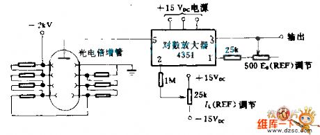
The wide range data of optoelectronics multiplier is sent by logarithmic amplifier 4351, in order to compress a data at in the range of ±5 V d.c., and sending to the magnetic tape recorder.
(View)
View full Circuit Diagram | Comments | Reading(487)
The inside circuit diagram of crystal triode DDC114TH、DDC114TH-7、DDC114YH、DDC114YH-7
Published:2011/3/24 1:02:00 Author:Ecco | Keyword: crystal triode
The inside circuit diagram of crystal triode DDC114TH、DDC114TH-7、DDC114YH、DDC114YH-7 is as below:
(View)
View full Circuit Diagram | Comments | Reading(424)
3000VA UPS Power Supply circuit
Published:2011/3/21 4:01:00 Author:Rebrecca | Keyword: UPS, Power Supply
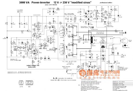
Here is the schematic diagram of the circuit: (View)
View full Circuit Diagram | Comments | Reading(3833)
Infrared micro-computer automatic pump fluid software designed circuit
Published:2011/3/22 22:45:00 Author:Joan | Keyword: Infrared micro-computer , automatic pump fluid, Infrared pump fluid
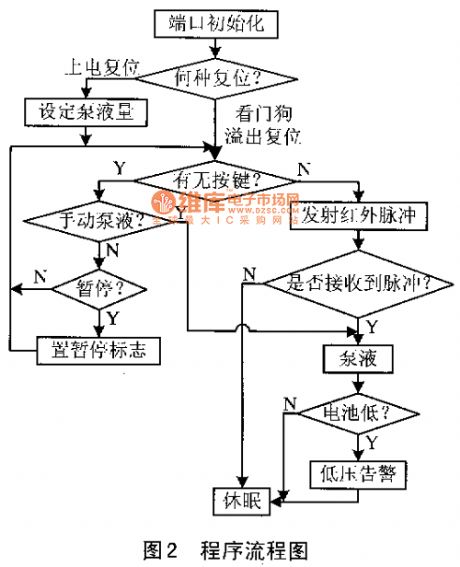
The circuit controls circuitry of each unit to save energy in hardware design, and uses PIC MCU sleep, WDT wake-up features and control of the number of transmit pulse to further reduce energy consumption in software design, which make the standby current less than 100μA, 4 section 4 alkaline batteries can provide more than 15 000 times or more than 200 days use time. The program flow is shown below.
The program first initializes each port on the microcontroller, and sets the watchdog timeout time. After a cycle of work procedures, it automatically enters in sleep mode, and will be woke-up by the microcontroller watchdog overflow into the next cycle.before entering into a working cycle, it first determines whether the battery power is the first on and works, or is woke up for microcontroller watchdog overflow.If the battery power is the first on and works, the light gives instruction and set the amount of pump fluid.When entering into the work cycle, it needs to determine whether the button is pressed. If the button is pressed, it needs to determine a manual pump fluid or suspend its work. Both of which is determined by that the time of the key being pressed is long or short.
Infrared transceiver program plays a key role in improving the interference resistance of pump fluid and reducing the energy consumption of the pump dispenser. Select a firing pulse frequency which is not sensitive to external interference light by experiments. To minimize energy consumption, the program set the number and method of the firing pulse. It starts two test pulses. When the pulses is received, it issues 60 consecutive pulses of the selected frequency, then determine whether the number of pulses received by the receiver is within the allowable range. It will pump fluid if the number is within the range, or will enter sleep mode if the number is not within the range. When the recipient does not receive test pulses, it will directly enter into sleep mode. Everytime the pump dispenser works, it checks the battery voltage. if it founds the battery is low voltage, it will alarm to replace the battery by the indicator.
System Features
Compared to the similar products, the infrared sensor pump dispenser has the following advantages:Compact, precision IC design. Low cost, low power consumption.4 section 4 alkaline batteries can provide more than 15 000 times or more than 200 days use time.High anti-interference ability, and correct operation. With removable magnetic valve, no leakage, easy to clean;Use high technology of paste, convenient and practical, without punching fixed. Plug and play technology of bottle liquid, fluid infusion without irrigation, eliminate the secondary pollution of the liquid. (View)
View full Circuit Diagram | Comments | Reading(809)
The inside circuit diagram of crystal triode UMD22N、EMD4
Published:2011/3/24 1:03:00 Author:Ecco | Keyword: crystal triode
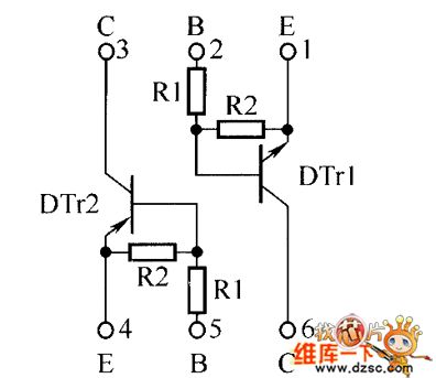
The inside circuit diagram of crystal triode UMD22N、EMD4 is as below:
(View)
View full Circuit Diagram | Comments | Reading(547)
The inside circuit diagram of crystal triode UMD4N、EMD5、UMD5N
Published:2011/3/24 1:03:00 Author:Ecco | Keyword: crystal triode

The inside circuit diagram of crystal triode UMD4N、EMD5、UMD5N is as below:
(View)
View full Circuit Diagram | Comments | Reading(548)
The inside circuit diagram of crystal triode EMD30
Published:2011/3/22 0:57:00 Author:Ecco | Keyword: The inside circuit
The inside circuit diagram of crystal triode EMD30 is as below:
(View)
View full Circuit Diagram | Comments | Reading(447)
The inside circuit diagram of crystal triode EMG1、UMG1N
Published:2011/3/24 1:02:00 Author:Ecco | Keyword: crystal triode
The inside circuit diagram of crystal triode EMG1、UMG1N is as below:
(View)
View full Circuit Diagram | Comments | Reading(489)
The inverted proportion circuit diagram
Published:2011/3/22 3:17:00 Author:Ecco | Keyword: inverted proportion
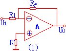
The inverted proportion circuit diagram is as below:
(View)
View full Circuit Diagram | Comments | Reading(456)
The inside circuit diagram of crystal triode EMG1N、UMG9N
Published:2011/3/24 1:02:00 Author:Ecco | Keyword: crystal triode

The inside circuit diagram of crystal triode EMG1N、UMG9N is as below:
(View)
View full Circuit Diagram | Comments | Reading(470)
| Pages:2204/2234 At 2022012202220322042205220622072208220922102211221222132214221522162217221822192220Under 20 |
Circuit Categories
power supply circuit
Amplifier Circuit
Basic Circuit
LED and Light Circuit
Sensor Circuit
Signal Processing
Electrical Equipment Circuit
Control Circuit
Remote Control Circuit
A/D-D/A Converter Circuit
Audio Circuit
Measuring and Test Circuit
Communication Circuit
Computer-Related Circuit
555 Circuit
Automotive Circuit
Repairing Circuit