
Circuit Diagram
Index 2200
TDA7293 Audio amplifier circuit diagram
Published:2011/3/30 21:30:00 Author:Ecco | Keyword: Audio amplifier

TDA7293 Audio amplifier function circuit diagram is as below:
(View)
View full Circuit Diagram | Comments | Reading(5429)
tda2004 circuit diagram 2
Published:2011/3/30 21:31:00 Author:Ecco
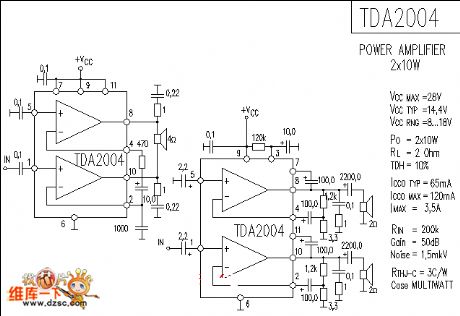
tda2004 circuit diagram 2 is as below:
(View)
View full Circuit Diagram | Comments | Reading(1161)
555 Timing control circuit diagram
Published:2011/3/30 21:31:00 Author:Ecco | Keyword: Timing control
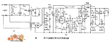
555 Timing control circuit diagram is as below:
(View)
View full Circuit Diagram | Comments | Reading(738)
tda1521 Application circuit diagram
Published:2011/3/30 21:32:00 Author:Ecco | Keyword: Application
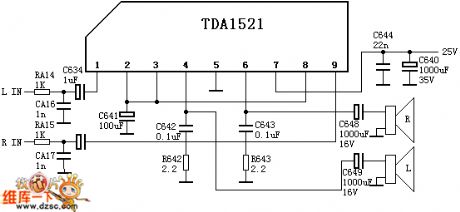
The Pinout function and referenced voltage of TDA1521:CSYN: 11V--inverted input 1(L sound channel input)VSYN: positive--going input 1VCH: 11V--consult 1(When OCL connection is 0V, OTL connection is 1/2 Vcc)SCK: 11V--output 1( L sound channel output)DI: 0V--negative electricity input(OTL connect to the earth)DO: 11V--output 2(R sound channel output)MON: 22V--positive electricity inputEXTCLK--positive-going input 2VCC--inverted input 2(L sound channel input) (View)
View full Circuit Diagram | Comments | Reading(2667)
Microampere meter internal resistance test circuit diagram
Published:2011/3/30 21:22:00 Author:Ecco | Keyword: microampere meter, internal resistance
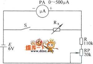
Microampere meter internal resistance test circuit diagram internal resistance test circuit diagram is as below:
(View)
View full Circuit Diagram | Comments | Reading(1283)
U disk circuit diagram
Published:2011/3/30 21:24:00 Author:Ecco | Keyword: U Disk
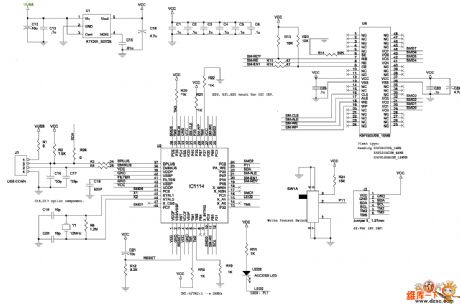
U disk circuit diagram is as below:
(View)
View full Circuit Diagram | Comments | Reading(878)
Super bass amplifier diagram made by LM3886
Published:2011/3/30 21:24:00 Author:Ecco | Keyword: Super bass amplifier
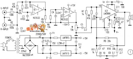
Super bass amplifier diagram made by LM3886 is as below:
(View)
View full Circuit Diagram | Comments | Reading(3826)
The power phase sequence indicator circuit diagram
Published:2011/3/30 21:29:00 Author:Ecco | Keyword: power phase sequence indicator
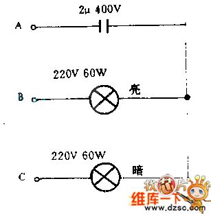
When operating, one port connects to one phase of power supply clamped by insulating handle, and the other port only need to touch the the other two phase of power supply, difference of brightness of the two lamps can quickly determine power sequence.
To set A phase is the port of capacitance, the bright port of lamp is B phase, weak light port is C phase.
Due to the influence of capacitance phase shifting, if change phase angle of any phase, the influence could make two kinds of vectors voltage be not equal to each other, the rules is always B phase vector voltage is greater than the C vector voltage.
(View)
View full Circuit Diagram | Comments | Reading(4941)
Sony WEGA ES series rear projection TV power supply circuit diagram
Published:2011/3/29 20:50:00 Author:Rebekka | Keyword: Sony WEGA ES series, rear projection TV
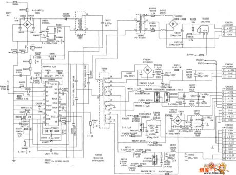
Here is the schematic diagram of the Sony WEGA ES series rear projection TV power supplycircuit:
(View)
View full Circuit Diagram | Comments | Reading(10115)
-55-+150℃ Digital thermometer circuit diagram
Published:2011/3/30 20:52:00 Author:Ecco | Keyword: -55-+150℃ Digital thermometer
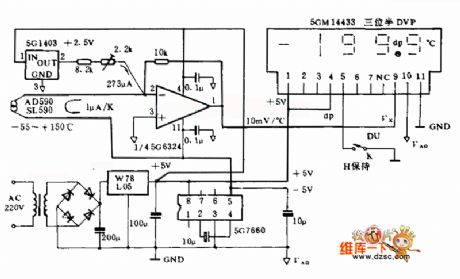
This digital thermometer electrocircuit is composed of SL590, a new semiconductor IC temperature-sensitive sensor and three half digital voltage panel 5GM14433, and it can measure the temperature in the range of -55~15o ℃. The SL590 make the temperature be a type of current semaphore, which become ratio's voltage semaphore at Celsius temperature after making the null point displacement by operational amplifier, and sent to the UX input terminal of 5GM14433, then be digital quantity displayed by LED. The supply is d.c two types, and alternating current supplyed by 220V, also could be supplyed by 4 pieces of 1.5V batteries.
(View)
View full Circuit Diagram | Comments | Reading(3195)
ne5532 operation amplifier circuit diagram
Published:2011/3/30 20:52:00 Author:Ecco | Keyword: ne5532 operation amplifier
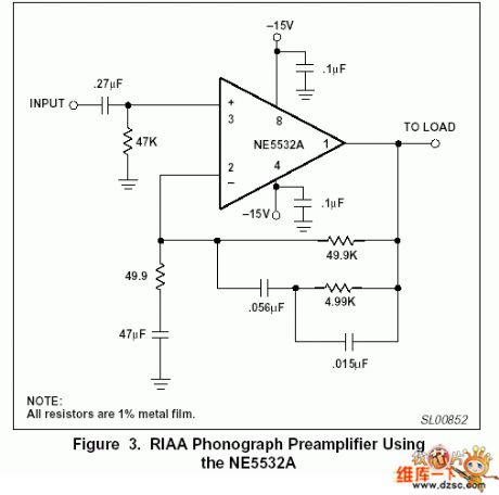
ne5532 operation amplifier circuit diagram is as below:
(View)
View full Circuit Diagram | Comments | Reading(9951)
The circuit diagram of TTL level displayed by LED
Published:2011/3/30 21:19:00 Author:Ecco | Keyword: TTL level, LED
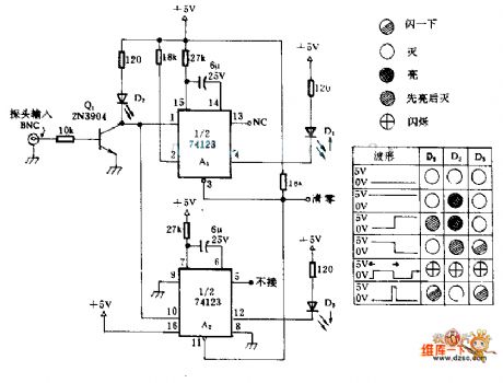
This circuitry could be used to observe the TTL electrical level when there's no cathode-ray oscillograph . 74123 integrated circuit contains two trigger type of monostable harmonic oscillators with input of zero clearing, and they are marked as A1 andA2 in this circuit respectively. When the input level changes, the tmonostable harmonic oscillator will light more light emitting diode. Because single firm extended the pulse width, even if the input brain is very narrow, naked eye can still arguing the brightness of diode. The exhibit explains three light-emitting diodes mean of different states. (View)
View full Circuit Diagram | Comments | Reading(1773)
Pontiac speaker circuit diagram
Published:2011/3/30 2:40:00 Author:Rebekka | Keyword: Pontiac speaker
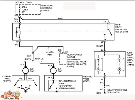
Here is the schematic diagram of the Pontiac speaker circuit:
(View)
View full Circuit Diagram | Comments | Reading(520)
Monolithic switching power supply circuit diagram
Published:2011/3/30 21:18:00 Author:Ecco | Keyword: Monolithic switching, power supply
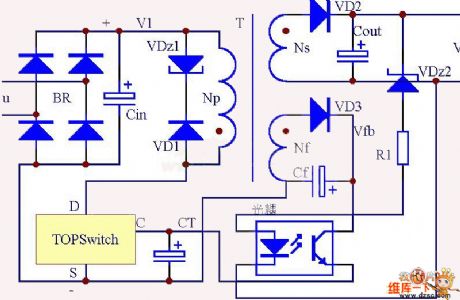
Monolithic switching power supply circuit diagram is as below:
(View)
View full Circuit Diagram | Comments | Reading(780)
Pontiac alarm system circuit diagram
Published:2011/3/30 2:42:00 Author:Rebekka | Keyword: Pontiac alarm system
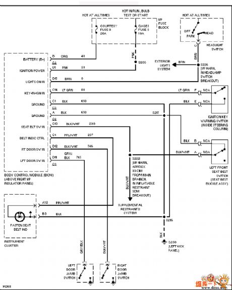
Here is the schematic diagram of the Pontiac alarm systemcircuit:
(View)
View full Circuit Diagram | Comments | Reading(530)
TV LED electronic forceps monitoring circuit diagram
Published:2011/3/30 21:19:00 Author:Ecco | Keyword: TV, LED electronic forceps
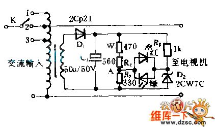
When the switch places(2), the output voltage is homology to input voltage, if the voltage were normal(200~240 V),both of two luminotrons couldn't be bright. When the voltage rises to 250 V, the rise of A electric potential will make red luminotron bright, when the switch places(2), then make output be 220V, the red luminotron again douses again. When Lou voltage drop arrived at 190 V, the green luminotron will be bright, the switch places(3).
(View)
View full Circuit Diagram | Comments | Reading(1395)
-40-+125℃ digital thermometer circuit diagram
Published:2011/3/30 20:42:00 Author:Ecco | Keyword: digital thermometer
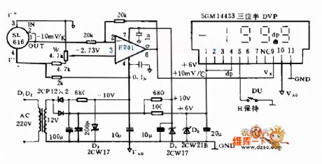
This digital thermometer electrocircuit is composed of SL616, a newsemiconductor IC temperature-sensitive sensor and three half digital voltage panel(DVP)s, and it uses the SL616 A to measure the temperature in the ranges of -40~125 ℃. And it uses the SL161 C to measure the temperature in the ranges of -25~85 ℃, measurement accuracy after correcting is ±0.5 ℃. Its power supply use 3 sets of +6 V, ±the 10, and only +6 V power supply consume higher current(about the 65 mas), each ±10 V power supply the only consume about 3 mA current.
The digital thermometer creates corresponds thermal voltage semaphore(-10 mVs/K), then the semaphor is become ratio's voltage semaphore(+10 mVs/℃) at Celsius temperature after making the null point displacement by operational amplifier, and sent to DVP to carry on digitize display as thermal amount of indication.
(View)
View full Circuit Diagram | Comments | Reading(2391)
Pontiac starting system circuit diagram
Published:2011/3/30 2:44:00 Author:Rebekka | Keyword: Pontiac starting system
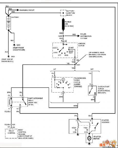
Here is the schematic diagram of the Pontiac starting system circuit:
(View)
View full Circuit Diagram | Comments | Reading(732)
The regulated power supply circuit diagram with constant current and parallel connection
Published:2011/3/30 20:43:00 Author:Ecco | Keyword: constant current, parallel connection, regulated power supply

The electric circuit is a type of constant current paralleling supply, it has the features of high speed, low noise, low internal resistance. Adopting the LM317 as a constant current source, it can provide constant current with 560 mA to load. The field-effect tube 2SR3D and luminotron tube can provide low noisy reference voltage. The LM741(Operational Amplifier) is an error amplifier to compare and amplify the reference voltage and sampling voltage. Two sets of 3DD15 are been used to adjust output voltage to hit the purpose of stabilizing the output voltage.
(View)
View full Circuit Diagram | Comments | Reading(3474)
Pontiac motor window circuit diagram
Published:2011/3/30 2:46:00 Author:Rebekka | Keyword: Pontiac motor window
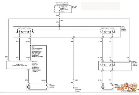
Here is the schematic diagram of the Pontiac motor windowcircuit:
(View)
View full Circuit Diagram | Comments | Reading(519)
| Pages:2200/2234 At 2021812182218321842185218621872188218921902191219221932194219521962197219821992200Under 20 |
Circuit Categories
power supply circuit
Amplifier Circuit
Basic Circuit
LED and Light Circuit
Sensor Circuit
Signal Processing
Electrical Equipment Circuit
Control Circuit
Remote Control Circuit
A/D-D/A Converter Circuit
Audio Circuit
Measuring and Test Circuit
Communication Circuit
Computer-Related Circuit
555 Circuit
Automotive Circuit
Repairing Circuit