
Circuit Diagram
Index 2185
74 series digital circuit of 7449 74LS49 BCD seven segment decoder/driver
Published:2011/4/1 3:23:00 Author:Ecco | Keyword: digital circuit, BCD seven segment , decoder, driver
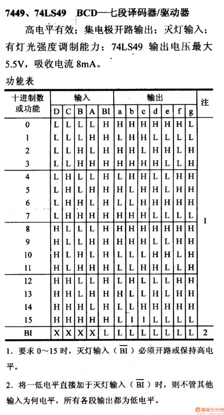
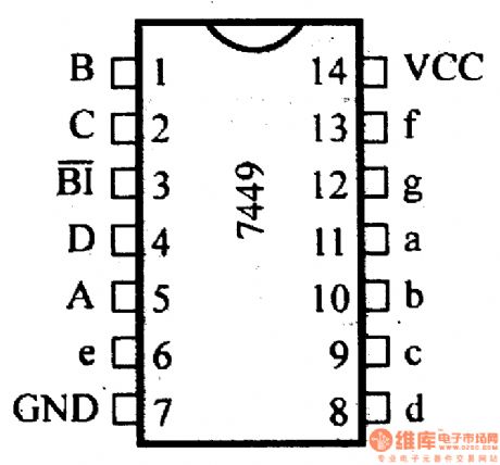
Effective high level; Collector circuit output; Turning off input; Having the function of light intensity modulation; The maximumoutput voltage of 74LS49 is 5.5V, absorbing current is 8mA.
(View)
View full Circuit Diagram | Comments | Reading(3277)
74 series digital circuit of 74LS86 74F86 quad 2 input exclusive-or gate
Published:2011/3/31 0:54:00 Author:Ecco | Keyword: digital circuit , quad 2 input , exclusive-or gate
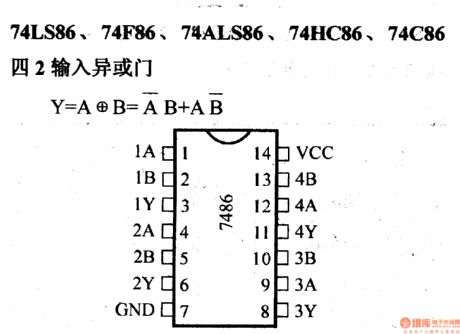
74 series digital circuit of 74LS86 74F86 quad 2 input exclusive-or gate
(View)
View full Circuit Diagram | Comments | Reading(2755)
74 series digital circuit of 7448A 74LS48 BCD seven segment decoder/driver
Published:2011/4/1 3:18:00 Author:Ecco | Keyword: digital circuit, BCD , seven segment, decoder, driver
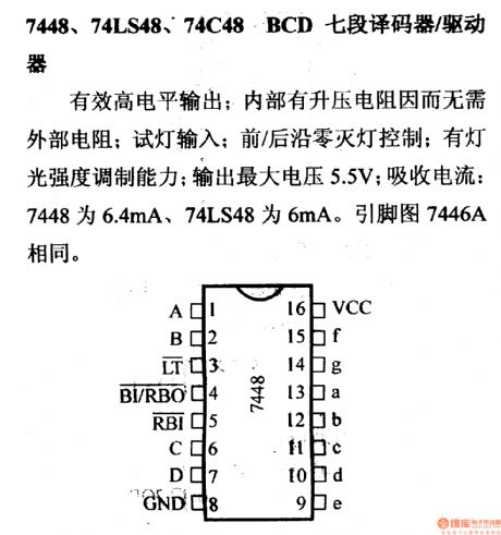
7448A, 74LS48, 74C48BCD seven segment decoder/driver
Effective high output; There's an boost resistor inside the circuit, so there's no need to use external resistor; Pilot light input; Leading edge and back porch zero lights turning off control; Having the function of light intensity modulation; The maximum output voltage is 5.5V; Absorbing current: 6448 is 6.4mA, 74LS48 is 6mA. The pin is 7446A.
(View)
View full Circuit Diagram | Comments | Reading(3905)
74 series digital circuit of 7485 74LS85 4 pull amplitude comparator
Published:2011/3/31 21:36:00 Author:Ecco | Keyword: digital circuit, 4 pull, amplitude comparator
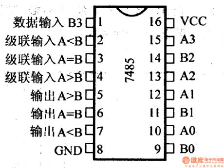
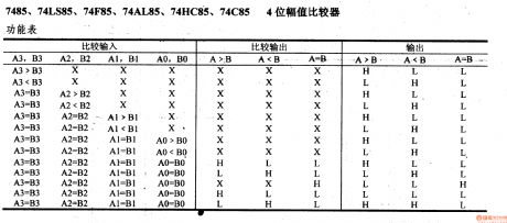
74 series digital circuit of 7485 74LS85 4 pull amplitude comparator
(View)
View full Circuit Diagram | Comments | Reading(4377)
74 series digital circuit of 7483A 74LS83A synchronous 4 binary full adder
Published:2011/3/31 21:33:00 Author:Ecco | Keyword: digital circuit, synchronous 4, binary full adder
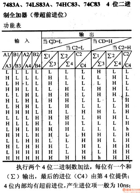
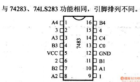
7483A, 74LS83A, 74HC83, 74C83synchronous 4 binary full adder(carry lookahead)
(View)
View full Circuit Diagram | Comments | Reading(4422)
74 series digital circuit of 7480 door input full adder
Published:2011/3/31 22:43:00 Author:Ecco | Keyword: digital circuit, door input, full adder
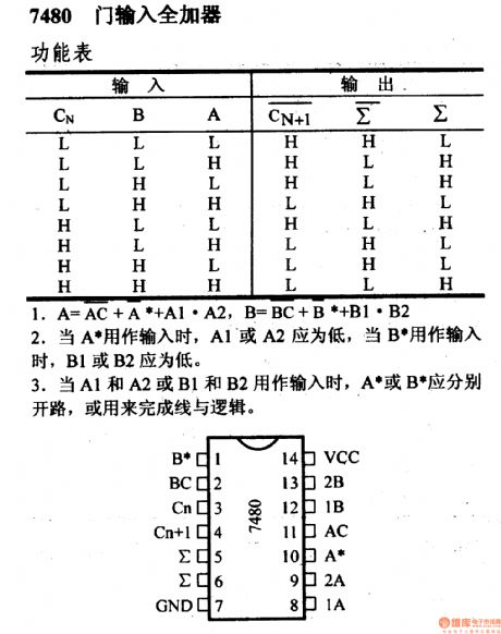
7480 door input full adder
1.A=AC+A*+A1·A2, B=BC+B+B1·B22.When A* is used as input, A1 and A2 should be low, when B* is used as input, B1 and B2 should be low.3. When A1 and A2 or B1 and B2 are used as input, A* or B* should be used as completing line and logic.
(View)
View full Circuit Diagram | Comments | Reading(1668)
74LS78A 74HC78 double J - K negative edge trigger( with preset public clear and public clock terminal)
Published:2011/3/31 22:36:00 Author:Ecco | Keyword: double J - K , negative edge , trigger, public clear terminal, public clock terminal, preset
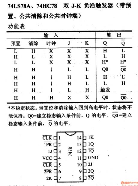
74LS78A 74HC78 double J - K negative edge trigger( with preset public clear and public clock terminal)
Unsteady state. When the preset and remove terminal return in high level, the state could not be kept. And the level of Qo is equal to Q before eatablishing steadystate input. (View)
View full Circuit Diagram | Comments | Reading(871)
74 series digital circuit of 7475 74L75 4-bit bistable D-type latch
Published:2011/4/1 1:00:00 Author:Ecco | Keyword: digital circuit , 4-bit, bistable, D-type latch
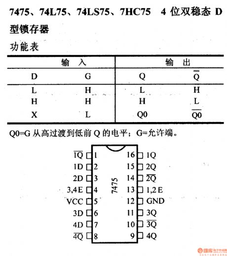
7475, 74L75, 74LS75, 7HC754-bit bistable D-type latch
The Q's level from Qo to G, which is from high level to low level: G=allowable terminal. (View)
View full Circuit Diagram | Comments | Reading(3485)
74 series digital circuit of 7472 74H72 input J - K master-slave flip-flop
Published:2011/4/1 0:43:00 Author:Ecco | Keyword: digital circuit, input J - K , master-slave flip-flop
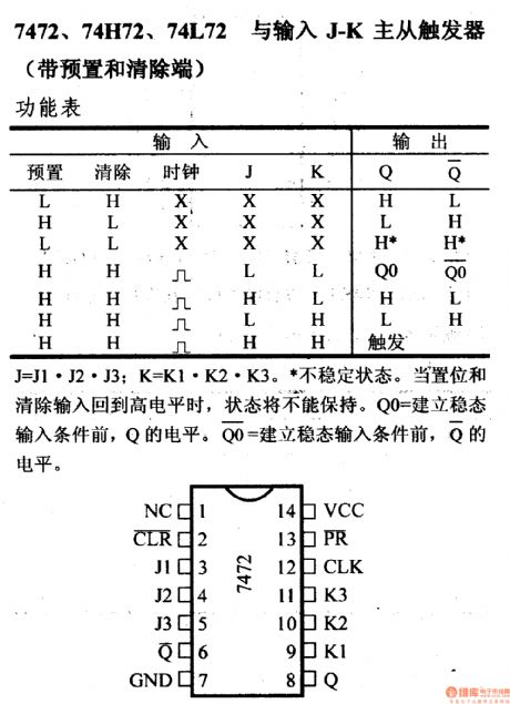
7472, 74H72,74L72 input J - K master-slave flip-flop(with preset and remove terminal)
Unsteady state. When the preset and remove terminal return in high level, the state could not be kept. And the level of Qo is equal to Q before eatablishing steadystate input. (View)
View full Circuit Diagram | Comments | Reading(1512)
74 series digital circuit of 7470 input J - K positive edge trigger
Published:2011/4/1 1:50:00 Author:Ecco | Keyword: digital circuit, input J - K, positive edge, trigger
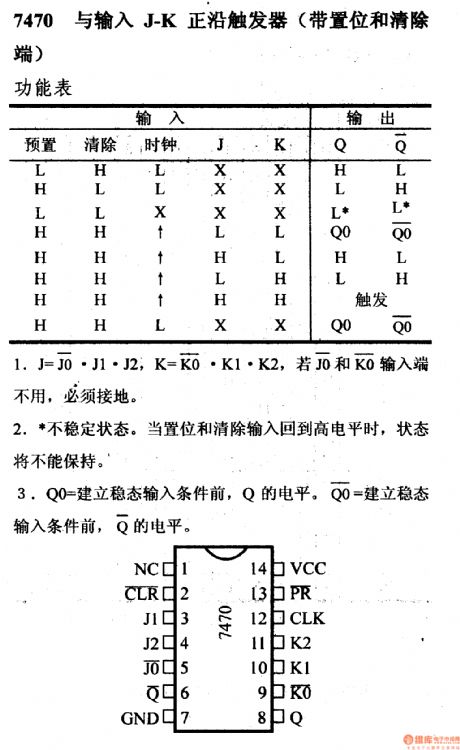
7470 input J - K positive edge trigger (with set and remove terminal)
Unsteady state. When the preset and remove terminal return in high level, the state could not be kept. And the level of Qo is equal to Q before eatablishing steadystate input. (View)
View full Circuit Diagram | Comments | Reading(659)
74 series digital circuit of 7468 dual decade counter
Published:2011/4/1 1:20:00 Author:Ecco | Keyword: digital circuit, dual decade , counter
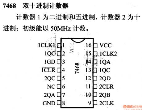
The counter 1 is in binary and quinary system, the counter 2 is a kind of decade counter. The primary is counting with 50MHz. (View)
View full Circuit Diagram | Comments | Reading(1895)
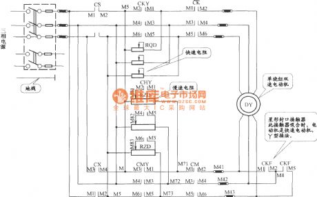
JHo-751 Semi-automatic cargo elevator main circuit
Published:2011/3/28 1:17:00 Author:Jessie | Keyword: Semi-automatic, cargo elevator
View full Circuit Diagram | Comments | Reading(958)
74 series digital circuit of 74HC58 3 input expander
Published:2011/4/1 2:40:00 Author:Ecco | Keyword: digital circuit , 3 input, expander
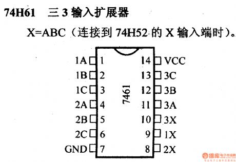
74H61 3 input expander
X=ABC(when connecting to the Xinput terminal of 74H52) (View)
View full Circuit Diagram | Comments | Reading(588)
+5V-+12V boost pressure supply circuit diagram
Published:2011/4/1 1:23:00 Author:Ecco | Keyword: boost pressure supply
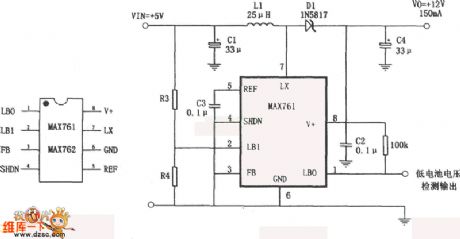
The boost pressure supply is composed of an efficient, low-power boosting d.c. convertor MAX761 and a few outer circle components. Its characteristics are: the efficiency of conversion is is 86%;The quiescent current is 110 μ A; Having the function of measuring the voltage of low batteries. In the chart, R3, R4 are divider resistances to measure the voltage of batteries, their value is generally counted according to the formula of R4=R3(VTPIP/1.5-1, and VTPIP is measuring triggering voltage. (View)
View full Circuit Diagram | Comments | Reading(1112)
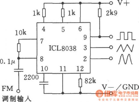
The applied circuit 1 of monolithic precision function generator ICL8038
Published:2011/3/31 3:20:00 Author:Ecco | Keyword: applied circuit, monolithic, precision function generator
View full Circuit Diagram | Comments | Reading(3117)
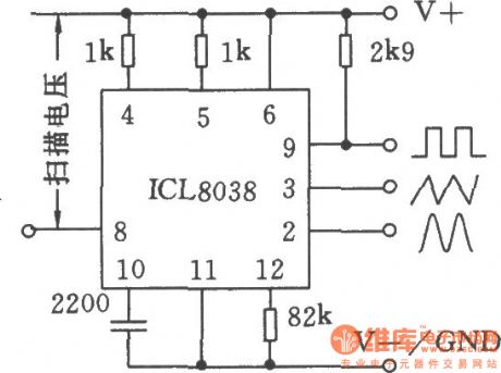
The applied circuit 2 of monolithic precision function generator ICL8038
Published:2011/3/31 3:19:00 Author:Ecco | Keyword: applied circuit, monolithic , precision function generator
View full Circuit Diagram | Comments | Reading(1123)
Logarithmic Amplifier Circuit
Published:2011/3/17 1:00:00 Author: | Keyword: Logarithmic Amplifier

Logarithmic Amplifier Circuit is show in the following picture:
(View)
View full Circuit Diagram | Comments | Reading(0)
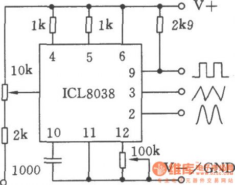
The applied circuit 3 of monolithic precision function generator ICL8038
Published:2011/3/31 3:18:00 Author:Ecco | Keyword: applied circuit , monolithic, precision function generator
View full Circuit Diagram | Comments | Reading(1929)
Practical pulse signal generator
Published:2011/3/31 3:36:00 Author:Ecco | Keyword: Practical, pulse signal , generator
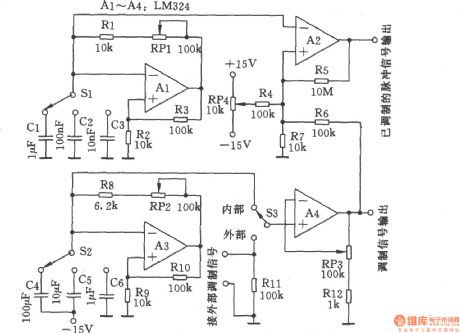
Practical pulse signal generator is adjustable and shown in the chart.
The pulse frequency generation circuit is composed of Al and surrounding components, it connects to three different capacitances which corresponding to three frequency ranges respectively. RPl is used as fine-tuning the frequency. A3 and surrounding components compose of signal modulation circuit, and it divides in three block range, RP2 is used as fine-tuning the signal modulation frequency. RP3 is for the gain modulation of modulating signal. RP4 controls duty ratio. (View)
View full Circuit Diagram | Comments | Reading(970)
Amplifier With Multipath Buffer Circuit
Published:2011/3/22 3:48:00 Author:may | Keyword: amplifier, multipath buffer
Amplifier With Multipath Buffer Circuit is shown in the following picture:
(View)
View full Circuit Diagram | Comments | Reading(539)
| Pages:2185/2234 At 2021812182218321842185218621872188218921902191219221932194219521962197219821992200Under 20 |
Circuit Categories
power supply circuit
Amplifier Circuit
Basic Circuit
LED and Light Circuit
Sensor Circuit
Signal Processing
Electrical Equipment Circuit
Control Circuit
Remote Control Circuit
A/D-D/A Converter Circuit
Audio Circuit
Measuring and Test Circuit
Communication Circuit
Computer-Related Circuit
555 Circuit
Automotive Circuit
Repairing Circuit